An Area Efficient Design of Fully Pipelined, 2D-DCT,
Quantizer and Zigzag JPEG Encoder using VHDL
Durga Patidar, Jaikaran Singh, Mukesh Tiwari,
Department of Electronics and Communication Engineering Sri Satya Sai Institute of Science and Technology, Sehore M.P. India
ABSTRACT
Image compression is the reduction or elimination of redundancy in data representation in order to achieve reduction in storage and communication cost. For this we use the simple computational method, 2D-DCT, using two 1D-DCT performed on matrix of (8X8). The 1D-DCT is a technique that converts a signal from spatial domain to frequency domain. Here we first convert the image into minimum code units. Then 2-D DCT is applied on each block. Then further process of Quantization, Zig-Zag approach and encoding is applied on the processed data. The architecture uses 3049 slices, 2,457 LUT, 46 I/Os of Xilinx Spartan-3 XC3S1600
General Terms
Image CompressionKeywords
1D-DCT, 2D-DCT, Quantization, Zig-Zag Approach
1. INTRODUCTION
Image compression aims to minimize the number of bits required in representing an image so as to produce new image representation that can be stored and transmitted efficiently. An image is a 2-D signal usually in analog form. But for processing (storage and transmission) by computer, they are converted from analog to digital form. Digital image or data is represented as a combination of information and redundancy. The raw digital image contain huge amount of information and therefore require a large channel or storage capacity. In spite of advances in communications channel and storage capacity, the implementation cost often put constraint on capacity. As the bandwidth requirement increase parallel the transmission or storage cost also increase, so it is necessary to employ compression techniques, which reduce the data rate while maintaining the subjective quality of the decoded image or video signal. Compression of data is the technique to minimize the redundancies in data representation in order to decrease data storage requirements and hence communication costs. Image compression techniques achieve compression by exploiting statistical redundancies in the data and eliminating or reducing data to which the human eye is less sensitive. A common characteristic of most images is that the neighboring
pixels are correlated and thus contain redundant information. The main goal of image compression is to reduce or remove this redundancy. In general, two types of redundancy:
1.1
Spatial redundancy
This refers to the correlation between neighboring pixels. This is the only redundancy for grayscale images.
1.2 Spectral redundancy
This refers to the correlation between different color planes or spectral bands. This redundancy occurs in color images or multispectral images and exists together with the spatial redundancy.
Image compression techniques aim at reducing the number of bits needed to represent an image by removing the spatial and spectral redundancies as much as possible. The compression is lossless if the redundancy reduction does not result in any loss of information in the original image [1].
DCT is mainly used for digital processing application because of its energy compaction characteristics. The development of efficient algorithms for the computation of DCT began soon after Ahmed et al [8] reported their work on DCT. Many algorithms for fast computation of DCT are reported in the literature [6-7].
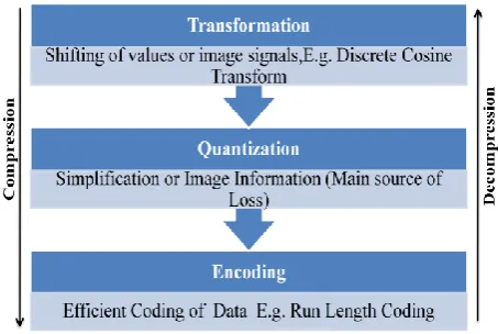
[image:1.595.319.546.498.650.2]Fig 2: Block diagram of Image compression
2. METHODOLOGY
2.1 Discrete Cosine Transform
The DCT is a technique that converts a signal spatial domain to frequency domain.DCT has property of higher energy compaction compared to DFT, DST, WHT and DWT. Hence, DCT is generally used for image and video compression. The image is first converted into minimum code units. Then 2-D DCT is applied on each block.
2.2 2-D Discrete Cosine Transform
The 2-D DCT of a data matrix is defined as equation (1)……….. (1)
Where X is the data matrix, C is the matrix of DCT Coefficients, and Ct is the Transpose of C. An expanded form of (1) is as followed:
Where, for an N x N data matrix,
For k= 1, 2… N, l= 2, 3… N, C k, l =N1/ 2 for l= 1
[image:2.595.315.553.377.489.2]The 2-D DCT is implemented by the row-column decomposition technique. We first compute the 1-D DCT (8 x 1 DCT) of each column of the input data matrix X to yield XTC after appropriate rounding or truncation, the transpose of the resulting matrix, CTX, is stored in an transpose buffer. We then compute another 1-D DCT (8 x 1 DCT) of each row of CTX to yield the desired 2-D DCT as defined in equation (1).
Fig 3: 2D- DCT Process
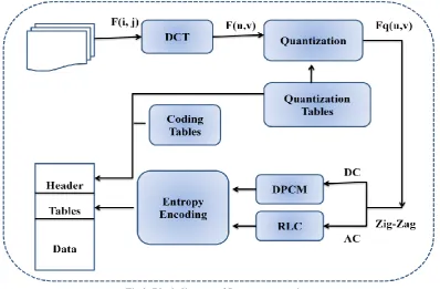
2.3 JPEG
The term "JPEG" means Joint Photographic Experts Group. JPEG mainly used for lossy compression of digital photography (image). The degree of compression can be adjusted, allowing a selectable tradeoff between storage size and image quality. JPEG typically achieves 10:1 compression with little perceptible loss in image quality JPEG compression is used in a number of image file formats. JPEG is the most common image format used by digital cameras and other photographic image capture devices; along with JPEG, it is the most common format for storing and transmitting photographic images on the Web. These format variations are often not distinguished, and are simply called JPEG.
2.4 Quantization
quantization in JPEG and DWT data quantization in JPEG 2000.
A typical video codec works by breaking the picture into discrete blocks (8×8 pixels). These blocks can then be subjected to discrete cosine transform (DCT) to calculate the frequency components, both horizontally and vertically. The resulting block (the same size as the original block) is then pre-multiplied by the quantization scale code and divided element-wise by the quantization matrix, and rounding each resultant element. The quantization matrix is designed to provide more resolution to more perceivable frequency components over less perceivable components (usually lower frequencies over high frequencies) in addition to transforming as many components to 0, which can be encoded with greatest efficiency. Typically the quantized matrix which is obtained from quantization has values primarily in the upper left (low frequency) corner. By using a Zig-Zag ordering to group the non-zero entries and run length encoding, the quantized matrix can be much more efficiently stored than the non-quantized version.
This is an example of DCT coefficient matrix:
A common quantization matrix is:
For example, using −415 (the DC coefficient) and rounding to the nearest integer
= -26
[image:3.595.315.559.72.267.2]Typically this process will result in matrices with values primarily in the upper left corner.
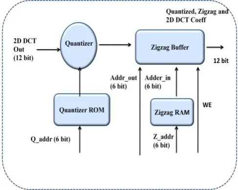
Fig 4: Quantization & Zig-zag Architecture
2.5 Zig-Zag Reordering
[image:3.595.53.280.325.512.2]Each block of data that is output by the quantization module needs to be reordered, so we use zigzag reordering. This reordering is achieved using an 8 x 8 array of register pairs organized in a fashion similar to the transpose buffer. Quantized output is sent sequentially byte-by-byte in zigzag pattern. Zigzag operation is done for every 8X8 block (fig 5).
Fig 5: Zig-zag Reordering
2.6 Entropy Coder
This is the final processing step of the JPEG encoder. Entropy Coding (EC) achieves additional compression lossless by encoding the quantized DCT coefficients more compactly based on their statistical characteristics.
2.6.1 Huffman encoding
Huffman coding uses a specific method for choosing the representation for each symbol, resulting in a prefix code (sometimes called "prefix-free codes", that is, the bit string representing some particular symbol is never a prefix of the bit string representing any other symbol) that expresses the most common source symbols using shorter strings of bits than are used for less common source symbols.
2.6.2 Run length encoding
than as the original run. In our example, let take a screen containing plain black text on a solid white background.
Let us take a hypothetical single scan line, with B representing a black pixel and W representing white. WWWWWWWWWWWWBWWWWWWWWWWWWBB BWWWWWWWWWWWWWWWWWWWWWW BWWWWWWWWWWWWWW
If we apply the run-length encoding data compression algorithm then 12W1B12W3B24W1B14W Interpret this as twelve W's, one B, twelve W's, three B's, etc.
3. SIMULATION RESULTS
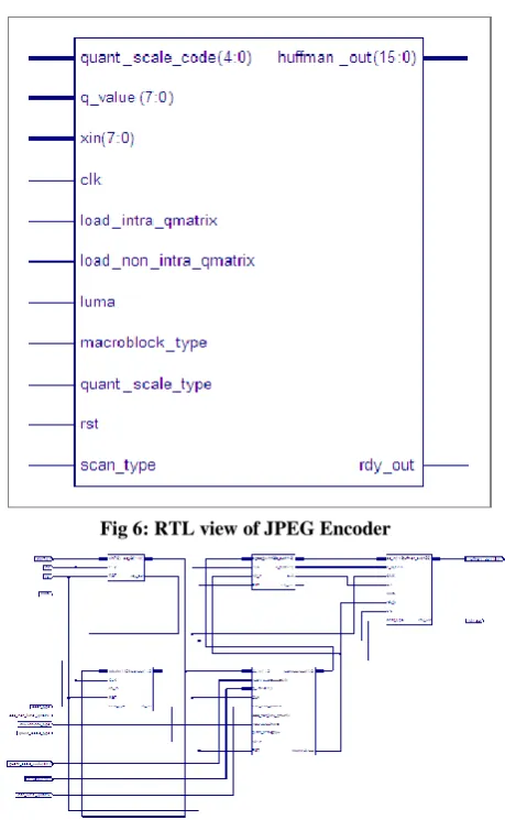
[image:4.595.319.551.73.265.2]In this paper an area efficient JPEG image compression using VHDL has been implemented.
[image:4.595.55.285.252.625.2]Fig 6: RTL view of JPEG Encoder
Fig 7: RTL Schematic Design of JPEG compression modules
Fig 8: Device Utilization Summary
[image:4.595.318.553.298.437.2]We have tested our design using Modelsim and simulation, synthesis has been done using Xilinx ISE Spartan3 device.
Fig 9: Simulation Result for 2D- DCT
Simulation of VHDL values are compared with paper
presented in [1]. The complete synthesis results of Xilinx
Spartan-3 XC3S1600 FPGA are presented in table 1.
Table 1: Device utilization using Xilinx spartran-3E for
total architecture proposed in this paper
Logic Units Used Available Utilization
Number of slices 2410 14752 16%
Number of slices FFs 3090 29504 10%
Number of 4 input LUTs 2408 29504 8%
Number of Bonded IOBs 46 376 18%
Number of multipliers 13 36 36%
The architecture uses 2410 slices, 2408 LUT, 46 I/Os of Xilinx Spartan-3 XC3S1600
4. ACKNOWLEDGMENTS
[image:4.595.316.553.546.648.2]necessary facilities and true encouraging environment to bring out the best of my endeavors. I also extend my deepest gratitude to Dr. G. R. Selokar, Principal, SSSIST, Sehore for providing all the necessary facilities and true encouraging environment to bring out the best of my endeavors. I also acknowledge my parents, family and Friends for the moral support they extended to me in completion of this paper work.
5. REFERENCES
[1]. Sanjeevan nanavar, S. A.N Nagamani, .,“Efficient design and FPGA implementation of JPEG encoder using verilog HDL” Nanoscience, Engineering and Technology (ICONSET), 2011 International Conference on Nov. 2011.
[2]. P. Subramanian, , A.S.C. Reddy, “VLSI Implementation of fully pipelined multiplierless 2D DCT/IDCT architecture for JPEG”, Signal Processing (ICSP), 2010 IEEE 10th International Conference on Oct. 2010.
[3]. Xing Wang, Xinhuan Feng, Nianfeng He, Qilong Jia, Ying Zou, “JPEG image compression algorithm analysis and local optimization” Advanced Management Science (ICAMS), 2010 IEEE International Conference on
[4]. T.Pradeepthi and Addanki Purna Ramesh ,” Pipelined architecture of 2D-DCT, Quantization and Zigzag process for JPEG image compression using VHDL” International Journal of VLSI design & Communication Systems (VLSICS) Vol.2, No.3, September 2011.
[5]. Vijaya Prakash.A.M , K.S., “GurumurthyA Novel VLSI
Architecture for Image Compression Model Using Low power Discrete Cosine Transform” World Academy of Science, Engineering and Technology 72 2010.
[6]. Nam Ik Cho, Sang Uk Lee “Fast Algorithm and
Implementation of 2-D Discrete CosineTransform”, IEEE Transaction on Circuits and Systems, Vol.38, No.3, March 1991.
[7]. E. Magli, “The JPEG Family of Coding Standard,” Part
of “Document and Image Compression”, New York: Taylor and Francis, 2004.
[8]. Heyne and J. Goetz A low-power and high-quality implementation of the discrete cosine transformation,Adv. Radio Sci., 5, 305311, 2007.
[9]. Vijay Kumar Sharma, Umesh C. Pati, and K. K. Mahapatra “A Simple VLSI Architecture for Computation of 2-D DCT, Quantization and Zig-zag ordering for JPEG”.
[10].L. Agostini, S. Bampi, “Pipelined Fast 2-D DCT
Architecture for JPEG Image Compression” Proceedings of the 14th Annual Symposium on Integrated Circuits and Systems Design, Pirenopolis, Brazil. IEEE Computer Society 2001. pp 226-231.
[11].Sherif T. EID Shams University Cairo “A Low Power
1-D 1-DCT/I1-DCT Core”. 1999 -Y2k.
[12].Ken Cabeen and Peter Gent Math 45 College of the Redwoods Image Compression and Discrete Cosine Transform.
[13].Andrew B.Watson,Image compression using the discrete cosine transform, Mathematical Journal, 4(1), 1994, p, 81-88.
[14].VijayaPrakash and K.S.Gurumurthy.A Novel VLSI Architecture for Digital Image Compression UsingDiscrete Cosine Transform and Quantization IJCSNS September 2010.