International Journal of Emerging Technology and Advanced Engineering
Website: www.ijetae.com (ISSN 2250-2459,ISO 9001:2008Certified Journal, Volume 3, Issue 1, January 2013)
243
An Investigationof Non Destructive Testing of Pressure Vessel
Mohd Abdul Wahed1, Mohammed Farhan2 1,2
Assistant Professor, Departmentof MechanicaL Engineering, Nsakcet,AP-500024
Abstract--Non-Destructive Testing (NDT) is related to identifying the presence of those defects, imperfections and discontinuities in the finished product which impair the performance level. Many defects are also generated during service. The nature of this defects differ according to the design, processing, fabrication and service conditions under which the components have to work. Knowledge of these defects with a view to detect and evaluate them and then minimizing them in the product is essential to achieve improve or acceptable level of quality. Improvements in the product quality increase its reliability and in turn the safety of the machines and equipment, thus bringing economic returns to the user. There is therefore a need to know the methods by which the defects in the products can be examined without affecting their performance.
Keywords--Non destructive testing, Pressure vessel, Magnetic particle testing, ultra sonic testing, Ultra sonic flaw detector.
I. INTRODUCTION
[image:1.612.361.527.196.319.2]Non-Destructive Testing (NDT) is the term used in connection to represent the techniques that are based on the application of physical principles employed for the purpose of determining the characteristics of materials or system and for detecting and assessing the in homogeneities and harmful defects without impairing the usefulness of such materials or components or systems.An NDT method ranges from the simple to the intricate. Visual inspection is simplest of all. Surface imperfection in visible to the eye may be revealed by penetrant or magnetic methods. If serious surface defects are found, there are often little points in proceeding further to more complicated examination of the interior by other methods like ultrasonic or radiography. The principle optical methods are visual or optical inspection, dye penetrant testing, magnetic particle testing, eddy current testing, radiography testing, and ultrasonic testing.
Figure 0: Pressure Vessel of 1 bar Pressure
II. EQUIPMENT CHARACTERISTICS
2.1 Horizontallinearity or time-base linearity or sweep linearity:
This process assumes that the horizontal scale is linear i.e., equal distances represent equal thickness. For example, if the 5th division on the horizontal scale represents 50mm 10th division represents 100mm, then the second division should represent 20mm and the 8th division should represent 80mm and so on. If this does not happen the horizontal scale is non-linear.
Horizontal linearity is equipment characteristic and is independent of the probe. Horizontal non-linearity cannot be rectified by the operator. However a correction graph can be prepared showing scale division verses actual thickness. Horizontal linearity is important for measuring thickness or foraccurate flaw location.
[image:1.612.360.531.541.664.2]International Journal of Emerging Technology and Advanced Engineering
Website: www.ijetae.com (ISSN 2250-2459,ISO 9001:2008Certified Journal, Volume 3, Issue 1, January 2013)
244
2.2Amplifier linearity or vertical linearity:
Vertical linearity or amplifier linearity refers to height of echo „A‟ being proportional to signal height „a‟ as provided by the probe, irrespective of the value of „A‟.
For example, assume that we have signals giving echoes of heights 40% and 80% of full scale height of CRT. Now, if the gain is reduced such that the first echo becomes 30%, the second echo should become 60% (i.e., maintain the same ratio of 2). If this does not happen, the amplifier is not linear.
The equipment may show linearity up to certain height on the CRT. The vertical height of CRT where the linearity no longer exists is called vertical limit. In some equipment it may be observed that the echoes do not go beyond a particular limit even when gain is increased. This is called the saturation limit or saturation point. While using the UFD one should always operate below the vertical limit and saturation limit.
[image:2.612.88.252.397.510.2]Vertical linearity is also equipment characteristic and is independent of the probe. Non-linearity cannot be corrected by the operator. This linearity is important when echo heightratios are to be recorded.
Figure 2: Vertical Linearity
2.3 Correctness of amplifier gain control (db control): The gain control calibrated in dB helps to compare echo heights in terms of dB which of course can be converted into linear ratios, if required. The calibration of the dB control should be accurate. For example, an increase of gain by 6dB should increase the echo height by a factor 2 and a decrease of gain by 20dB should decrease the echo height by a factor of 10. (See appendix on dB versus linear ratio). If this does not happen, the dB control calibration (i.e. markings) is not alright.
The amplifier linearity along with dB control calibration accuracy permit us to reliably compare the heights of any two echoes.
2.4 Resolution (spatial resolution):
Resolution is the ability to show distinct and well separate echoes from defects which are close to each other.
Two cases arise (1) defects which are separated by a small distance along the axis of the beam and (2) defects separated by a small distance perpendicular to the beam axis. The first case is called depth resolution (or axial resolution) and the second is called lateral resolution.
Resolution is more dependent on probe than on the flaw detector. Lateral resolution improves with narrower beams. Depth resolution improves with narrower pulses. Narrower pulses are obtained by increasing frequency or increasing damping.
We have already learnt about DEAD ZONE. It is obvious that the dead zone is nothing but NEAR SURFACE RESOLUTION (or the lack of it). NEAR SURFACE RESOLUTION is the ability to resolve reflectors close to the entry surface from the transmitted pulse. Larger the dead zone, poorer the near surface resolution (or, in other words, less dead zone)
The resolution explained earlier is also called FAR SURFACE RESOLUTION (as against near surface resolution).
The instrument controls DAMPING and FILTERING can affect resolution. Higher damping and lesser filtering improve resolution. Lower pulse enrages and amplification also helps in bettering resolution.
2.5 Sensitivity:
Sensitivity is defined as the ability to detect small defects. Sensitivity is dependent on both the instrument and probe characteristics. Higher frequency leads to better sensitivity in general. However if the thickness range is high or the attenuation in the material is high, higher frequency may lead to reduced sensitivity. Damping decreases sensitivity.
Higher pulse energy and higher amplification increase sensitivity. Use of suppression (reject) can prevent small echoes from being seen.
III. GENERATION &DETECTION OF ULTRASOUND
The generation and detection of ultrasound is done by the device called transducers. A transducer is any device that is capable of converting energy from one form to another, a mechanical energy to electrical energy and vice versa. This is called PIEZO-ELECTRIC EFFECT.
International Journal of Emerging Technology and Advanced Engineering
Website: www.ijetae.com (ISSN 2250-2459,ISO 9001:2008Certified Journal, Volume 3, Issue 1, January 2013)
245
Fig3: Different Types of Transducers
IV. PROBE CONSTRUCTION
[image:3.612.84.254.137.218.2]There are several types of transmitter probe in use but each type consists of a crystal, which is placed in contact, either directly or through a protective cover with the material under test. There are several materials, which may be used as transducer crystals, and these include natural quartz, bariumtitanate, and lead niobate and lithium sulphate. A step voltage, of short duration, is applied to the crystal and this causes the crystal to vibrate at its natural frequency. After the step voltage has been removed the crystal oscillation is required to die as soon as possible, and the crystal is usually backed by a damping material to assist this process.
Figure 4: Probe Construction
V. MAGNETIC PARTICLE TESTING
a)Principle of magnetic particle testing: Magnetic Particle Testing is a sensitive method of locating surface and some sub-surface defects in ferromagnetic components. The basic processing parameters depend on relatively simple concepts. In essence, when a ferromagnetic component is magnetized, magnetic discontinuities that lie in a direction approximately perpendicular to the field direction will result in the formation of a strong ‘Leakage field’ (Flux leakage). This leakage field is present at and above the surface of the magnetized component, and its presence can be visibly detected by the utilization of finely divided magnetic particles. The application of dry particles or wet particles in a liquid carrier, over the surface of the component, results in a collection of magnetic particles at a discontinuity.
The „Magnetic Bridge‟ so formed indicates the location, size and shape of the discontinuity. Magnetization may be induced in a component by using permanent magnets, electromagnets or by passing high currents through or around the component. The latter technique is widely used for production quality control application because high-intensity magnetic field can be generated within components. Hence, good sensitivity in flaw indication and detection is attained.
[image:3.612.364.526.261.433.2]b)Magnetic particle testing procedure:
fig 5: magnetic particle testing procedure
VI. METHODS AND TECHNIQUE APPLIED
1)Magneticparticle testing:As the Pressure vessel was fabricated from a ferromagnetic material and hence Magnetic Particle Testing could be employed. Dry and fluorescent continuous magnetic particle testing was carried out. It was used to detect the surface and sub-surface defects in the weld region. Current was passed through as in a straight conductor which created a circular magnetic field. Magnetization of the component was accomplished by making the component, a part of the electrical circuit by means of a hand yoke. Direct current (DC) was used to detect subsurface as well as surface defects. This type of magnetization was carried out over the entire weld region of the fabricated Pressure vessel. This magnetization was limited to the spacing between the legs of the magnetic yoke. The yoke used was of SIMS, Hyderabad make. The current used was half wave direct current (HWDC) with amperage of 800 Amps. Since the material being a soft material, continuous method was employed. The Dry Continuous method is very sensitive and will give indications of very fine defects.
POST CLEANING DEMAGNETIZATION
INTERPRETATION REMOVAL OF PARTICLES APPLICATION OF PARTICLES
MAGNETIZATION DEMAGNETIZATION
International Journal of Emerging Technology and Advanced Engineering
Website: www.ijetae.com (ISSN 2250-2459,ISO 9001:2008Certified Journal, Volume 3, Issue 1, January 2013)
246
The depth of magnetization is around 6mm. There was no need for demagnetization as the component was of soft material which loses its magnetic field once supply is switched off. Very high sensitiveness are possible with wet particle inspection, particularly where a fluorescent powder is used and inspection is made under Ultra-Violet light. The detecting medium was Magnoflux of ITWS India Ltd make, fluorescent powder in Wet Magnetic Particle Testing and Automag of NDT consumables for Dry Visible Powder Magnetic Particle Testing. The various accessories used were Black Lamp 100W, Magnetic Hand Yoke and ferromagnetic particle powder as mentioned above.
2) Ultrasonictesting:This technique is applied to detect both surface and sub-surface (internal) defects. Ultrasonic sound waves of frequency 4 MHz for 00 probe and 700 were used. A 40 SAE Couplant Oil was employed as coupling agent between the transducer crystal and the metal so as to decrease the reflection of waves at the metal crystal interface. An Ultrasonic beam being transmitted through a metal will be totally reflected at the far surface of the material, a metal / air interface. It will be also be wholly or partially reflected by any internal surface, namely cracks or laminations, porosity and non-metallic inclusions, subject to the limitation that the size of the object is not less than one wavelength. In the ultrasonic test equipment the signals were displayed on the screen of a Cathode Ray Oscilloscope (CRT). The equipment used was Modsonic Einstein TFT-II digital CRT of Modsonic Equipment manufacturer, Ahmedabad make.Both angle and normal probes were used. The probes used were 00 probe of 10Φ PI - NM make and 700 of 8 x 9 mm size probe of PI make. Reflection technique was employed in which access to only one surface was required. A radial defect in a cylindrical member is not generally detectable using normal probe inspection, as the defect will be parallel to the ultrasonic beam, in these circumstances the use of an angle probe reflection technique will clearly show the presence of defects. In many cases the fact that a defect is present does not necessarily mean that a component must be thrown out. Defects may be tolerated provided that they do not exceed a certain acceptable size. One of the benefits of Ultrasonic Testing is that defect size can be accurately determined. In order to be able to determine defect size accurately, the oscilloscope must be calibrated and this is done with the aid of test pieces containing artificial defects of certain specific sizes.
As far as the reference blocks are concerned a 20 mm Side Drilled Holes amplitude block was used. Area amplitude blocks are made from material with the same acoustic properties as that of the test component.
Artificial flaws of different sizes are machined to the same depth in the reference block. For calibration purpose IIW (International Institute of Welding) steel calibration blocks were used for the calibration of both angle beam and direct beam probes prior to contact inspection of component. The Scanning was done 49db for 00 probes and 56db for 700 probes.
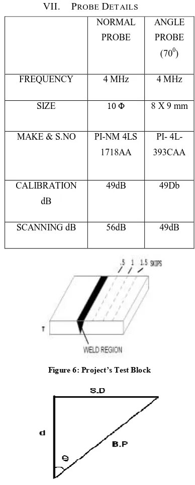
VII. PROBE DETAILS
NORMAL
PROBE
ANGLE
PROBE
(700)
FREQUENCY 4 MHz 4 MHz
SIZE 10 Φ 8 X 9 mm
MAKE & S.NO PI-NM 4LS
1718AA
PI- 4L-
393CAA
CALIBRATION
dB
49dB 49Db
[image:4.612.345.539.227.708.2]SCANNING dB 56dB 49dB
Figure 6: Project’s Test Block
International Journal of Emerging Technology and Advanced Engineering
Website: www.ijetae.com (ISSN 2250-2459,ISO 9001:2008Certified Journal, Volume 3, Issue 1, January 2013)
[image:5.612.90.245.127.332.2]247
Figure 8: Calibration Echoes
Figure 9: Graph showing Acceptable and reject able area for the component
Tan θ = S.D / d (S.D = Surface Distance) Sin θ = S.D / B.P
B.P = Beam Path Cos θ = d / B.P (d = depth)
Depth S.D B.P
t/4 d1=5 13.73 14.70
t/2 d2=10 27.47 29.41
[image:5.612.370.526.142.221.2]3t/4 d3=15 41.21 44.11
Table: Dimensions of testing
VIII. RESULTS AND CONCLUSION
[image:5.612.352.532.316.522.2]In the region of Long seam weld and circumferential seam weld few undercuts, porosity, porus along with hair line crack has been observed.
Figure 10: Inspection showing defects viz; porosity
Figure 11: Hair line crack observed under ultraviolet lamp
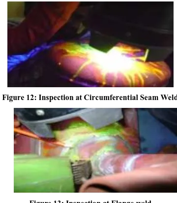
No significant indications were found on the circumferential seam weld at two parting plane, one each on left and right side when magnetic particle test was employed. Also Ultrasonic Inspection established that the welding done was under acceptable limits and no further machining process is required like grinding.
Figure 12: Inspection at Circumferential Seam Weld
Figure 13: Inspection at Flange weld
Magnetic particle testing could not be applied to its fullest at varying cross sections as the current selection was difficult. If high current was used then it would permanently magnetize the component and interfere with other accessories in vicinity. Ultrasonic testing could not be performed to its fullest at different contours.
REFERENCES
[1 ] M.G. Silk, Ultrasonic Transducers for Non-Destructive Testing,
Adam Hilger Ltd.
[2 ] R. Halmshaw (Editor), “Mathematics and formulae in NDT”, British
Institute Non Destructive Testing.
[3 ] Baldev Raj, T. Jayakumar, M. Thivasimuthu, “Practical
Non-Destructive Testing”, Narosa Publishers, Second Edition.
[4 ] J. L. Taylor, “Basic Metallurgy for Non-Destructive Testing”,
[image:5.612.45.251.362.555.2] [image:5.612.91.245.606.708.2]International Journal of Emerging Technology and Advanced Engineering
Website: www.ijetae.com (ISSN 2250-2459,ISO 9001:2008Certified Journal, Volume 3, Issue 1, January 2013)
248
[5 ] ASM Metals and Handbook, Vol-II, “Non Destructive Inspection &
Quality Control”, American Society of Metals.
[6 ] Handbook on Ultrasonic Examination of Welds, International
Institute of Welding.
[7 ] R.W. Nichols, Int. J. Pres. Ves. & piping Vol-II (50) 1992, Elsevier