i
TWO-WHEELED BALANCING ROBOT CONTROLLER DESIGNED USING PID
SUHARDI AZLIY BIN JUNOH
A project report submitted in partial fulfillment of the requirement for the award of the
Master of Electrical Engineering
Faculty of Electrical and Electronic Engineering Universiti Tun Hussein Onn Malaysia
iv
ABSTRACT
v
ABSTRAK
vi
CONTENTS
TITLE i
DECLARATION ii
ACKNOWLEDGEMENT iii
ABSTRACT iv
ABSTRAK v
CONTENTS vi
LIST OF TABLES ix
LIST OF FIGURES x
LIST OF SYMBOLS AND ABBREVIATIONS xii
LIST OF APPENDICES xiv
CHAPTER 1 INTRODUCTION 1
1.1 Project background 2
1.2 Problem statement 2
1.3 Aim and objective 3
1.4 Scope of works 3
1.5 Outline of thesis 4
CHAPTER 2 LITERATURE REVIEW 5
2.1 Two wheel balancing robot 5
vii 2.3 Types of controller to balance two wheels
robot 10
2.4 Balancing two wheel robot with PID 14
CHAPTER 3 METHODOLOGY 15
3.1 Introduction 15
3.2 Hardware development 17
3.2.1 IMU sensor 18
3.2.2 Arduino board 19
3.2.3 DC geared motor 19
3.3 Software development 20
3.3.1 Matlab and Simulink 21
3.3.2 I2C interface 21
3.3.3 PID controller 22
3.3.4 The characteristics of PID controller 24 3.3.5 PID tuning (Ziegler-Nichols tuning) 24 3.4 Modelling of two wheeled inverted pendulum
robot 25
3.4.1 State-space equations 29
CHAPTER 4 RESULT AND ANALYSIS 30
4.1 Introduction 30
4.2 Simulink result 30
4.3 Hardware 37
4.3.1 MPU6050 analysis 39
viii
4.3.3 PID tuning analysis 46
4.3.4 Comparison of simulation result and hardware 50
4.3.5 Robot balancing performance 51
4.3.6 Comparison of prototype 1 and prototype 2 55
CHAPTER 5 CONCLUSION 57
5.1 Conclusion 57
5.2 Future works 58
REEFERENCES 59
ix
LIST OF TABLES
2.1 Parameters of the inverted pendulum 10
2.2 Previous technique to control two wheel robot 13
3.1 Comparison between Accelerometer and Gyroscope in IMU 18
3.2 Effect of PID tuning 24
3.3 PID tuning in Ziegler-Nichols method 25
4.1 Specification of the robot parameter 31
x
LIST OF FIGURES
2.1 JOE developed by Grasser et.al [7] 6
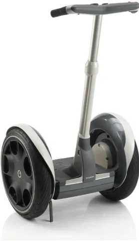
2.2 Segway PT 7
2.3 nBot developed by Anderson [8] 8
2.4 Eyebot developed by Rich Ooi (adapted from [9]) 8 2.5 Free body diagram of the inverted pendulum system
(adapted from [11]) 9
3.1 Flow chart of the system 16
3.2 Block diagram of the hardware 17
3.3 IMU board 18
3.4 Arduino Uno board 19
3.5 DC geared motor 20
3.6 I2C protocol 22
3.7 Set point and actual tilt angle of robot 22
3.8 Response curve for Ziegler – Nichols Method 25
3.9 Free body diagram of the developed system 26
3.10 Wheels of the robot (adapted from [9]) 26
3.11 Free body diagram of the chassis (adapted from [24]) 28
4.1 Response for uncontrolled robot 31
xi
4.8 Overview of hardware 37
4.9 Block diagram of feedback control system 37
4.10 Error of angle vs PWM (speed) 38
4.11 Angle offset vs time 39
4.12 Angle with filtering vs time 40
4.13 Speed vs PWM (left motor) 41
4.14 Voltage vs speed (left motor) 42
4.15 Speed vs PWM (right motor) 42
4.16 Voltage vs speed (right motor) 43
4.17 The output voltage on PWM 128 45
4.18 The output voltage on PWM 200 45
4.19 Angle response with PID control Kp=1, Ki=0, Kd=0 46 4.20 Angle response with PID control Kp=5, Ki=0, Kd=0 47 4.21 Angle response with PID control Kp=10, Ki=0.1, Kd=0 48 4.22 Angle response with PID control Kp=8, Ki=0.4, Kd=0.1 49 4.23 Angle response with PID control Kp=80, Ki=20, Kd=1 50
4.24 Balancing on rough surface such as carpet 52
4.25 Balancing on carpet with a load 52
4.26 Balancing on flat surface with a load 53
4.27 Balancing on flat surface with more load 1 53
4.28 Balancing on flat surface with more load 2 54
4.29 Angle response when disturbance is applied 55
4.30 Front and side view of first prototype 56
4.31 Top view of first prototype 56
xii
LIST OF SYMBOLS AND ABBREVIATIONS
M - Mass of the cart m - Mass of the pendulum b - Friction of the cart l - Length of the pendulum
I - Inertia
F - Force applied to the cart g - Gravitational acceleration r - Wheel radius
Mw - Wheel mass
Mp - Body mass
Iw - Wheel inertia Ip - Body inertia Km - Motor torque
Ke - Back EMF
R - Terminal resistance Va - Applied terminal voltage - Vertical pendulum angle
- Angular velocity x - Cart position
x - Cart speed
e0 - Error of angle
ev - Error of velocity
xiii Ki - Integral gain
Kd - Derivative gain
xiv
LIST OF A APPENDICES
APPENDIX TITLE PAGE
A Left motor speed and PWM 62
B Right motor speed and PWM 63
C Schematic diagram 64
D Matlab code for open loop and PID 65
E Polyadd function in Matlab 66
1
CHAPTER 1
INTRODUCTION
1.1 Project background
A two wheel self-balancing robot is an important kind of mobile robots. Balancing robots means the capability of the robot to balance on its two wheels without falling. The inverted pendulum system, unlike many other control systems is naturally unstable. Therefore, the system has to be controlled to reach stability in this unstable state. A two-wheeled balancing robot is simply an inverted pendulum system which stands upright on two wheels.
2 1.2 Problem statement
Mobile robots are increasingly implemented today and are used in a variety of different applications, including exploration, search and rescue, materials handling in hazardous area and entertainment. While legged robots are able to step over obstacles, they are more complex to design and control due to the greater number of degrees of freedom. Wheeled robots are more energy efficient, tend to have a simpler mechanical structure, as well as simpler dynamics compared to that required by legged robots to make contact with the ground and provide a driving force. Robots with at least three wheels can achieve static stability, further simplifying dynamics.
The inverted pendulum system is naturally unstable. Therefore, a suitable control system technique and method needs to be investigated to control the system. The two-wheel balancing robot is an application of the inverted pendulum that requires a controller to maintain its upright position. To achieve this, a controller needs to be designed and implement on the robot to balance the inverted pendulum.
3 1.3 Aim and objective
The development of the two wheel robot based on the inverted pendulum concept by using PID controller is the aim of this research. In order to achieve this aim, the objectives as follows are formulated;
i. To perform the simulation of a two-wheeled balancing robot based on its existing mathematical model with the robot’ actual parameters.
ii. To design and develop the prototype for two-wheel balancing robot with PID controller.
iii. To evaluate the performance of the developed self-balancing robot using a standard approach.
1.4 Scope of works
i. Determine the mathematical model for a two wheel robot.
ii. Determine the specification of the robot actual parameters such as mass, inertia and motor torque.
iii. Simulate the PID controllers using MATLAB and compare the performance with the uncontrolled and controlled robot.
4 1.5 Outline of thesis
This project is classified into five chapters. The scope of each chapter is explained as below:
First chapter gives the background of the thesis, problem statement, aim and objective, scopes of works and outline of the thesis.
Chapter II is about the literature review, in which previous studies and theories related to this project are discussed and reviewed. It also describes about the wheel balancing robot, the concept of inverted pendulum, balancing the robot using PID, fuzzy, LQR and SMC. Literature review provides a background of this project and also gives and direction in this research.
Chapter III deals with a research methodology. It describes the detailed method that has been used to conduct this project. This chapter proposes the list of material that will be used for the hardware development such as IMU sensor, Arduino controller and DC motor. It also discusses the theory and application of PID controller of this project.
Chapter IV is for the results and discussion. This chapter will highlight the simulation result done in Matlab and and its implementation on the hardware. It also discusses the tuning method of PID in self-balancing robot.
5
CHAPTER 2
LITERATURE REVIEW
2.1 Two wheel balancing robot
Wheeled inverse pendulum model has gained lots of interest recently with the introduction of one popular commercial product (Segway) [4]. Dual-wheel robot has two wheels and an upright body frame where all the circuits are placed. It adjusts its position when it is about to fall forward or backward to avoid instability [5]. The advantage of a two wheel balancing robot is that there is no auxiliary wheel [6].
6
Figure 2.1: JOE developed by Grasser et.al [7].
7
Figure 2.2: Segway PT
8
Figure 2.3: nBot as developed by Anderson [8].
[image:20.612.241.415.463.674.2]Figure 2.4 shows the Eyebot, which is a two-wheeled autonomous robot developed by Rich Chi Ooi [9], a student from School of Mechanical Engineering, University of Western Australia in year 2003. This project was conducted in collaboration with the Centre of Intelligent Information Processing System (CIIPS) to investigate the use of Kalman Filter for sensor fusion.
9 The project examined the suitability and evaluated the performance of a Linear Quadratic Regulator (LQR) and a Pole-placement controller in balancing the robot. The LQR controller used several weighting matrix to obtain the appropriate control force to be applied to the system while the Pole placement placed the poles of the system to guarantee stability. Besides, the robot also utilized Proportional- Integral-Derivative (PID) controlled differential steering method for trajectory control. Kalman Filter has been successfully implemented in this project, which effectively eliminated the gyroscope drift, allowing an accurate estimate of the tilt angle and its derivative for the robot. In this project, the author also highlighted that the robustness of the system is not fully tested. More experiments are needed to evaluate the robustness of the system and fine tuning of the control algorithm is required for better performance.
The rapid increase of the aged population in Japan has invoked researchers to develop robotic wheelchairs to assist the infirm to move around [10]. The control system for an inverted pendulum is applied when the wheelchairs maneuvers a small step or road curbs.
2.2 Fundamental of inverted pendulum
[image:21.612.244.427.550.691.2]The inverted pendulum system is a classic control problem that is used in the field of Control Theory and Engineering to understand it’s dynamic. The system consists of an inverted pole with mass, m, hinged by an angle θ from vertical axis on a cart with mass, M, which is free to move in x directions as shown in Figure 2.5. A force, F is required to push the cart horizontally
10
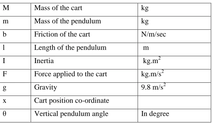
[image:22.612.154.493.149.346.2]The list of parameters of the inverted pendulum system is shown in Table 2.1
Table 2.1: Parameters of the inverted pendulum
M Mass of the cart kg
m Mass of the pendulum kg
b Friction of the cart N/m/sec
l Length of the pendulum m
I Inertia kg.m2
F Force applied to the cart kg.m/s2
g Gravity 9.8 m/s2
x Cart position co-ordinate
θ Vertical pendulum angle In degree
In order to obtain the system dynamics, the following assumptions have to be made [11].
i. The system starts in equilibrium state and the initial conditions are assumed to be zero.
ii. The pendulum does not move more than a few degrees away from the vertical to satisfy a linear model.
iii. A step input (displacement of the pendulum, θ) is applied to the system.
2.3 Types of controller to balance two wheel robot
There are a few types of the controller that have been developed by other researchers. Each of the controllers has its own method of designing which contain advantages and disadvantages.
11 enough for robot’s balance. When the appropriate Kp and Ki gain values are chosen for PI controller, it has been observed that the robot can balance itself for a short time and try to maintain its balance by swinging. In addition, when PID controller is applied, the two-wheel robot can stand in upright position longer compare to the previous two cases. This can be happen if only appropriate value of Kp, Ki, and Kd gain are chosen. Meanwhile, Nasir [13] states that PID controller capable to control the nonlinear inverted pendulum system angular and linear position in Matlab Simulink. However, PID controller should be improved so that the maximum overshoot for the linear and angular positions do not have high range as required by the design. W.An [14] claim that Matlab can be used to compare the performance of PID Controller and Linear-quadratic regulator (LQR) in controlling two-wheeled self-balancing robot. It is concluded that LQR has a better performance than PID in self-balancing control in term of the time to achieve the steady state of robot.
Meanwhile, according to J. Wu [1] that the fuzzy logic algorithm can realize the self-balance control of the two-wheeled robot and restrain the robot from falling down. In their paper, a fuzzy controller is applied to the dynamic model of the two-wheeled self-balancing robot. The simulation shows that the control methods have good performance in maintaining stability which resulting in short settling time and low overshoot.
The linear controllers are more popular among researcher designing similar balancing robots like JOE [7]. Linear state space controllers like the Pole placement controller and the Linear Quadratic Regulators (LQR) are the two most popular control system implemented. In the paper of Two Wheels Mobile Robot Using Optimal Regulator Control, N. M. Abdul Ghani [15] mentioned that Pole placement gives best performance in term of settling time and magnitude for position, speed, angle and angle rate of two wheels mobile robot. A comparison of the results has demonstrated that Pole placement control provide higher level of disturbance reduction as compared to LQR technique.
12 that LQR technique has a better efficiency than PID controller in self-balancing control based on the simulation result. But this technique is only work on simulation and for future research is to use LQR method to control a physical two-wheeled robot to verify the controller’s performance. The comparison of the performance of the controller is summarizing as shown in Table 2.2
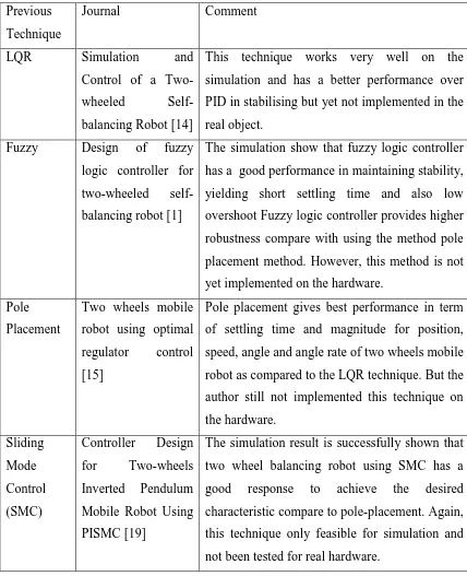
13 Table 2.2 : Previous technique to control two-wheel robots
Previous Technique
Journal Comment
LQR Simulation and
Control of a Two-wheeled Self-balancing Robot [14]
This technique works very well on the simulation and has a better performance over PID in stabilising but yet not implemented in the real object.
Fuzzy Design of fuzzy logic controller for two-wheeled self-balancing robot [1]
The simulation show that fuzzy logic controller has a good performance in maintaining stability, yielding short settling time and also low overshoot Fuzzy logic controller provides higher robustness compare with using the method pole placement method. However, this method is not yet implemented on the hardware.
Pole Placement
Two wheels mobile robot using optimal regulator control [15]
Pole placement gives best performance in term of settling time and magnitude for position, speed, angle and angle rate of two wheels mobile robot as compared to the LQR technique. But the author still not implemented this technique on the hardware.
Sliding Mode Control (SMC)
Controller Design for Two-wheels Inverted Pendulum Mobile Robot Using PISMC [19]
14 2.4 Balancing a two-wheel robot with PID
The PID has proven to be popular among the control engineering community. As stated by the author of article Vance J. Van Doren, “For more than 60 years after the introduction of Proportional-Integral-Derivative controllers, remain the workhorse of industrial process control” [21] The PID controller has proved to have an excellent behavior in controlling an unstable system. The real time controller is capable of taking right corrective action with certain shortcomings in maximum and minimum error regions which could be solved in the future by gain scheduling [22]
In the paper of Design and PID control of two wheeled autonomous balance robot, U. G. A. Unluturk [12] has proposed a method to balance the two wheel robot for a long time with optimum PID control parameters obtained. However, the system still requires Kalman filters to stabilize the robot.
In another paper of Design and Implementation of the Balance of Two- Wheeled Robots [23], the author said that the efficiency of the self-balancing robot is depend on the correct method of tuning the PID value. With improper tuning of PID value, robot will be unbalanced.
PID can be used if position and speed are not a concern and the system is to balance itself vertically only as stated by O.Jamil [24] He also stated that from all the simulated controllers this combination of PID showed the best performance compared with all the controllers applied. But analyzing the output can observe that the response is very slow for the position control.
15
CHAPTER 3
METHODOLOGY
3.1 Introduction
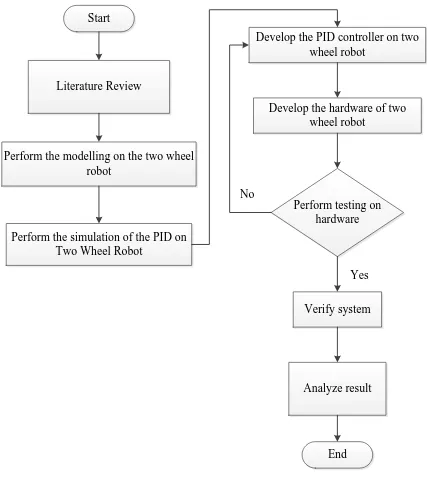
The methodology of this project is divided into two parts namely the mechanical design and the software algorithm. This chapter will describe the method for this subject in order to achieve the desired objective. The project will be developed based on a flowchart that determines all the necessary activities that has to be accomplished.
16
Start
Literature Review
Perform the modelling on the two wheel robot
Perform the simulation of the PID on Two Wheel Robot
Develop the PID controller on two wheel robot
Develop the hardware of two wheel robot
Perform testing on hardware
Verify system
Analyze result
End No
[image:28.612.113.540.70.559.2]Yes
17 3.2 Hardware development
The design of the hardware system is crucial in bringing the mechanism and software to work together. The main components in the circuit of the balancing robot are the inertial measurement unit (IMU), the Arduino controller and the DC servo motor. Figure 3.2 shows the overall block diagram of the electronic system for the balancing robot. The IMU is used to measure the acceleration and the angular rate of the robot and the output is processed into digital form. The raw inputs from the IMU are further processed to obtain the tilt angle of the robot. This tilt angle is then fed into the PID controller algorithm to generate the appropriate speed to the DC motor in order to balance the robot.
IMU
sensor Arduino Board
Motor Driver
Motor Driver DC Motor
Left
[image:29.612.165.489.319.666.2]DC Motor Right
18 3.2.1 IMU sensor
[image:30.612.279.374.336.474.2]In order to obtain the tilt angle of the balancing robot; the Six Degree of Freedom Inertial Measurement Unit (IMU) is used as in Figure 3.3. The MPU 6050 is a 6 DOF which means that it gives six values as output. The value consists three values from the accelerometer and three from the gyroscope. This chip uses I2C (Inter Integrated Circuit) protocol for communication. The module has on board Digital Motion Processor (DMP) capable of processing complex 9-axis Motion-Fusion algorithms. The SDA and SCL pins are used to establish a connection with the Arduino pins A4 and A5 to receive the accelerometer and gyroscope data. The interrupt pint (INT) is to instruct the Arduino when to read the data from the module and this pin instruct the Arduino only when the values change.
Figure 3.3 : IMU board
Table 3.1: Comparison between Accelerometer and Gyroscope in IMU
IMU Advantage Disadvantage
Accelerometer No bias Affected by object’s acceleration Gyroscope Unaffected by object’s
acceleration
Accumulated bias
[image:30.612.108.547.560.647.2]19 some calculations onboard to minimize the errors in each sensor. Accelerometers and gyros have different inherent limitations when used on their own as indicate in Table 3.1
3.2.2 Arduino board
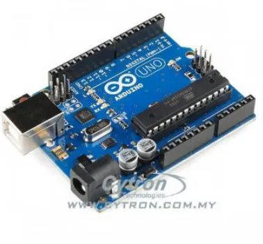
[image:31.612.235.424.290.465.2]The main controller chosen for the balancing robot is the Arduino Uno as shown in Figure 3.4. It can be considered as the brain of the balancing robot and is connected to the IMU to process the tilt angle information. After processing, it will communicate with the motor driver in order to adjust the speed and direction of the motor.
Figure 3.4 : Arduino Uno board
3.2.3 DC geared motor
20
Figure 3.5 : DC geared motor
For the DC motor used, below are the features of the DC motor:
i. Rated speed is 130rpm. The robot requires an average rpm so that it could counter the balancing error in a suitable speed. Low speed might not be able to balance the robot properly. Therefore, a higher rpm is chosen.
ii. Rated torque is 127.4 mN.m. The torque of the motors must be carefully chosen because a low torque might not be capable to balance the robot. The torque does not necessarily be too high. The torque required is based on the formula, Torque = Force x Distance
3.3 Software development
21 3.3.1 Matlab and Simulink
Matlab (short for MATrix LABoratory) is a language for technical computing, developed by the The Mathworks, Inc. It provides a single platform for computation, visualization, programming and software development. All problems and solutions in Matlab are expressed in notation used in linear algebra and essentially involve operations using matrices and vectors. Matlab can be used to solve problems in control systems.
Simulink is a tool for modeling, simulating and analyzing multi domain dynamic systems. Its primary interface is a graphical block diagramming tool and a customizable set of block libraries. Simulink is widely used in control theory and digital signal processing for multi domain simulation and design.
3.3.2 I2C interface
22
Figure 3.6: I2C protocol
3.3.3 PID controller
The control algorithm that is used to maintain its balance position on the self-balancing two wheel robot was the PID controller. The proportional, integral and derivative (PID) controller is well known as a three term controller. The Proportional Integral Derivative (PID) controller is a control loop feedback mechanism that is widely used in the industry. The controller attempts to adjust and correct the error between the measured process and the desired process and output corrective measures to adjust the process accordingly. This controller must be executed frequently enough and at the same time within the controllable range of the system.
[image:34.612.203.471.510.664.2]23 Figure 3.7 shows the set point and actual tilt angle of the two wheeled robot. The error is the difference between the actual tilt angle and the desired tilt angle (set point). As its name suggests, the PID controller contains of three parts, which are the proportional term, the integral term and the derivative term. These terms have different effect on the response of the DC motor. In order to balance the robot, the set point of the robot must be 0°.
The equation is simplified as below when the robot tilts to the front side as depict in Figure 3.7.
Error = Current Front Sensor Reading – Front Sensor Setpoint
The equation for the error is illustrated as below when the robot tilt to the back side.
Error = Back Sensor Setpoint – Current Back Sensor Reading
Below are the equations involved in calculating the output PID:
Output Proportional Term = Kp*Error
Output Integral Term = KpKi * Summation of Error * T
= KpKiT* (Summation of Error)
·Output Differential Term = Kp*Kd*(Error – Previous Error)/T
=(Kp*Kd/T)*(Error – Previous Error)
The simplification of the formula is as below.
Output Proportional Term = Kp*Error
Output Integral Term = Ki* (Summation of Error)
Output Differential Term = Kd*(Error – Previous Error)
Overall, the output PID controller for balancing control system will be:
Output PID controller = Output Proportional Term + Output Integral Term + Output
Differential Term
24 3.3.4 The characteristics of PID controller
[image:36.612.115.545.318.428.2]A proportional controller (Kp) will have the effect of reducing the rise time and will reduce but never eliminate the steady-state error. An integral control (Ki) will have the effect of eliminating the steady-state error for a constant or step input, but it may make the transient response slower. A derivative control (Kd) will have the effect of increasing the stability of the system, reducing the overshoot and improving the transient response. The effects of each of controller parameters, Kp, Kd and Ki on a closed loop system are summarized in the
Table 3.2: Effect of PID Tuning
Response Rise Time Overshoot Settling Time Steady State Error
Kp Decrease Increase Small Change Decrease
Ki Decrease Increase Increase Eliminate
Kd Small Change Decrease Decrease No change
Note that these correlations may not be exactly accurate because Kp, Ki and Kd are dependent on each other. In fact, changing one of these variables can change the effect of the other two.
3.3.5 PID tuning (Ziegler – Nichols tuning)
59
REFERENCES
[1] J. Wu, “Design of fuzzy logic controller for two-wheeled self-balancing robot,”
Proc. 2011 6th Int. Forum Strateg. Technol., pp. 1266–1270, Aug. 2011.
[2] A. Demetlika, “SELF-BALANCING MOBILE ROBOT TILTER,” vol. 3, pp. 23–32, 2012.
[3] L. I. U. Kun, B. A. I. Ming, and N. I. Yuhua, “Two-wheel self-balanced car based on Kalman filtering and PID algorithm.”
[4] D. Kamen, “Segway,” 2001. [Online]. Available: www.segway.com. [Accessed: 25-Apr-2015].
[5] U. Adeel, K. S. Alimgeer, O. Inam, A. Hameed, M. Qureshi, and M. Ashraf, “Autonomous Dual Wheel Self Balancing Robot Based on Microcontroller,” vol. 3, no. 1, pp. 843–848, 2013.
[6] J. Ha and J. Lee, “Position Control of Mobile Two Wheeled Inverted Pendulum Robot by Sliding Mode Control,” pp. 715–719, 2012.
[7] F. Grasser, A. D. Arrigo, S. Colombi, A. C. Rufer, and S. Member, “JOE : A Mobile , Inverted Pendulum,” no. February, pp. 107–114, 2002.
[8] “Anderson, D.P, 2003, ‘Nbot, a two wheel balancing robot’, Available from : http://www.geology.smu.edu/~dpa-www/robo/nbot/,” pp. 42–51.
[9] Rich Chi Ooi, “Balancing a Two-Wheeled Autonomous Robot,” Univ. West. Aust., Degree in Mechatronics Engineering, 2003.
[10] S. M. Y.Takahashi, S.Ogawa, “Step Climbing using Power Assist Wheel chair Robot with Inverse Pendulum Control,” no. April, pp. 1360–1365, 2000.
60 [12] U. G. A. Unluturk, O. Aydogdu, “Design and PID Control of Two Wheeled Autonomous Balance Robot Department of Electrical and Electronics Engineering , Selçuk University Electric-Electronic Engineer ANKARA / TURKEY,” pp. 260–264, 2013.
[13] A. N. K. Nasir, M. Z. M. Tumari, and M. R. Ghazali, “Performance comparison between Sliding Mode Controller SMC and Proportional-Integral-Derivative PID controller for a highly nonlinear two-wheeled balancing robot,” 6th Int. Conf. Soft Comput. Intell. Syst. 13th Int. Symp. Adv. Intell. Syst., pp. 1403–1408, Nov. 2012. [14] W. An, Y. Li, and S. Member, “Simulation and Control of a Two-wheeled
Self-balancing Robot,” no. December, pp. 456–461, 2013.
[15] N. M. A. Ghani, D. Ju, H. Z. Othman, and M. a. Ahmad, “Two wheels mobile robot using optimal regulator control,” 2010 10th Int. Conf. Intell. Syst. Des. Appl., pp. 1066–1070, Nov. 2010.
[16] S. K. K. Pawananont, “Design LQR Controller for the Balancing robot,” vol. 2, no. April 2010, pp. 174–177.
[17] J. S. V. Utkin, J. Guldner, Sliding Mode Control in Electro-mechanical Systems. Tylor and Francis, 1999.
[18] J.E Slotline and W.Li, Applied Nonlinear Control. Englewood Cliffs, New Jersey: Prentice-Hall, 1991.
[19] S. . Nawawi, M. . Ahmad, J. H. . Osman, a. . Husain, and M. . Abdollah, “Controller Design for Two-wheels Inverted Pendulum Mobile Robot Using PISMC,” 2006 4th Student Conf. Res. Dev., no. SCOReD, pp. 194–199, Jun. 2006.
[20] A. N. K. Nasir, R. M. T. R. Ismail, and M. A. Ahmad, “Performance Comparison between Sliding Mode Control ( SMC ) and PD-PID Controllers for a Nonlinear Inverted Pendulum System,” pp. 122–127, 2010.
[21] N. Maniha, A. Ghani, F. Naim, and T. P. Yon, “Two Wheels Balancing Robot with Line Following Capability,” vol. 5, no. 7, pp. 507–511, 2011.
61 [23] Y. Wen and Y. Lin, “Design and Implementation of the Balance of Two-
Wheeled Robots,” no. I, pp. 130–134, 2013.
[24] O. Jamil, M. Jamil, Y. Ayaz, and K. Ahmad, “Modeling , Control of a Two-Wheeled Self-Balancing Robot,” pp. 191–199, 2014.
![Figure 2.1: JOE developed by Grasser et.al [7].](https://thumb-us.123doks.com/thumbv2/123dok_us/8763763.895317/18.612.268.380.87.289/figure-joe-developed-grasser-et-al.webp)
![Figure 2.4: Eyebot developed by Rich Ooi (adapted from [9])](https://thumb-us.123doks.com/thumbv2/123dok_us/8763763.895317/20.612.241.415.463.674/figure-eyebot-developed-rich-ooi-adapted.webp)
![Figure 2.5: Free body diagram of the inverted pendulum system (adapted from [11])](https://thumb-us.123doks.com/thumbv2/123dok_us/8763763.895317/21.612.244.427.550.691/figure-free-body-diagram-inverted-pendulum-adapted.webp)