Journal of Chemical and Pharmaceutical Research, 2014, 6(7):2387-2393
Research Article
CODEN(USA) : JCPRC5
ISSN : 0975-7384
Meshing features of involute arc teeth cylindrical gears
Jiang Yiqiang
1,2, Hou Li
1, Sun Zhijun
1and Xiao Huajun
11
School of Manufacturing Science & Engineering, Sichuan University, Sichuan, China
2
Leshan Vocational & Technical College, Sichuan, China
_____________________________________________________________________________________________
ABSTRACT
This paper intended to derive the equation of the teeth surface of the involute arc cylindrical gear. Based on the forming principles of the teeth surfaces of the spur cylindrical gear and the helical cylindrical gear, an arc line parallel to the axis of the cylinder was firstly drawn in the generating plane, and then the scanning surface of the arc line should be the teeth surface of the involute arc cylindrical gear. After that, the equation of the arc line was derived and then the teeth surface. Finally the simulations of those equations were described with the instruments of proeWildfire 5.0 and MATLAB R2010a. Thus, the correctness of the equations was further proved.
Key words: involute; arc teeth; equation of the arc teeth surface
_____________________________________________________________________________________________
INTRODUCTION
Cylindrical gear transmission has found a widespread application in the industry. Currently, it mainly includes three modes of transmission: spur cylindrical gear,helical cylindrical gear and double helical cylindrical gear[1]. However,
there are some drawbacks in structures of the above-mentioned gears[2].
When spur cylindrical gears mesh, the instantaneous contact line of two teeth profile surfaces of the gears is parallel to their axes. Thus the teeth of the two gears throw into or out of the meshing along their teeth width in the process of transmission. Under this circumstance, the gear teeth are suddenly loaded or unloaded. Hence, a spur gear transmission might be poor of stability, susceptible to shock and vibrate and high likely to make noise. Spur gears are also possible to manufacture bigger error. In addition, due to the overlapping coefficient of spur gear transmission is small; the load on the gears is also limited.
Helical cylindrical gear has the following defects. Due to the unidirectional sloping teeth, the transmission drive will produce axial thrust. This thrust then cause that shafting structure of the gears is complex and friction losses is further increased. Thus, the transmission efficiency is reduced and the spiral angle is too some degree narrowed.
The third kind of gear, that is, double helical cylindrical gear, can overcome the above shortcomings; however, it also has such disadvantages as difficult and high-cost manufacturing, complicated structures and heavy weight.
Fig. 1: Appearance of the arc teeth cylindrical gear
At present, most of the researches are concentrated on the arc teeth cylindrical gear with involute teeth profile. The equations of its teeth surface are mainly set up based on the following two methods.
As for the first kind of method, the teeth surface is believed to be formed through scanning of an involute line along an arch line[1]. The equation of the teeth surface is set up through the geometric transformation. That is, this equation is derived from the plane meshing theory, but there is no equation of the arc line on the cylinder.
The second method suggests that the equation of the teeth surface should be derived based on the principle of processing and the movement rules between workpieces and cutters[2-4]. However, this kind of method has no solid theoretical foundation; in addition, the equation might be different according to different methods of processing.
Due to the drawbacks of the above methods, the application of arc teeth cylindrical gears has been greatly restricted.
This paper firstly proposes the forming principles of the teeth surface of involute arc teeth cylindrical gears through borrowing some principles of involute spur gears and involute helical gears. Based on those forming principles, the equation of the arc line on the cylinder is derived and then the equation of the teeth surface. Finally the correctness of those equations is proved by drawing equation figures through the instruments of proeWildfire 5.0 and MATLAB R2010a.
FORMING PRINCIPLES OF THE TEETH SURFACE OF INVOLUTE ARC CYLINDRICAL GEAR
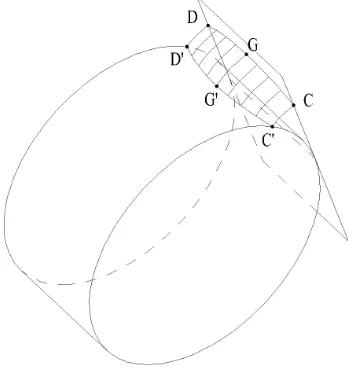
Let the radius of arc line CGD be Rt and its string line CD, which is parallel to the axis of the base cylinder; Then let curve C 'G' D ' be the imprinted arc line of CGD on the cylinder and the track surface of CGD the arc teeth surface of the involute arc cylindrical gear. If the teeth width is B, then Rt should be longer than half of B. Provided that, when Rt is +∞, the involute arc cylindrical gear shall become an involute spur cylindrical gear. The forming
principle of the teeth surface of the involute arc cylindrical gear is illustrated in fig. 2.
[image:2.595.218.392.541.726.2]EQUATION OF ARC LINE ON THE CYLINDER
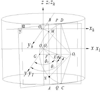
[image:3.595.208.402.174.351.2]If the axis of the cylinder is axis z and the radial cross-section is xoy coordinate plane, then the coordinate system o – xyz can be established on the rack of No. 1 gear. If the axis of the cylinder is axis z1 and the radial cross-section is x1o1y1 coordinate plane, then the coordinate system o1-x1y1z1 can be established on No. 1 gear. Now provided that axis y1 and axis y is located at the same position on No.1 gear, when the coordinate system o1-x1y1z1 is moved h (the distance) in the positive direction, the coordinate system oh-xhyhzh can be established on No. 1 gear. Thus the middle point of arc line CGD is located in axis y1. Ot is the center of the arc line CGD. And string line CD is parallel to axis Z1. All the above coordinate systems are shown in fig. 3.
Fig. 3: Coordinate systems on the cylinder
Now if the generating plane rotates on the cylinder, then the curve of the straight line OtG, which is imprinted on the cylinder, shall fall in the intersection of the plane of the coordinate x1o1y1 and the surface of the cylinder. Thus, Provided that the generating plane rotates toward any position (plane α), the turning angle of the plane is θb, the tangent line between the generating plane and the cylinder surface is AB, the point of intersection between CGD and AB is M and N, and the point of intersection between GOt and AB is F, then
/
b
GF R
bθ
=
(1)If the generating plane keeps rotating, then Point M and N shall begin to make an involute movement. Provided that the generating plane rotates until the plane γ, the turning angle is θt,; the abduction angle between M and N is Ф, the tangent line is PQ, and the point of intersection between GOt and PQ is E, then
b t
GE
=
R
θ
(2)And
+
b tφ θ θ
=
(3)Then in the plane right-angled triangle OtFM, if the distance between point M and straight line OtG is h, then h shall be between -B/2 and B/2. According to Pythagorean Theorem, we have
2 2
t t
O F
=
R
−
h
(4)And
2 2
t t t t
GF
=
O G O F
−
= −
R
R
−
h
(5)2 2
/
(
) /
b
GF R
bR
tR
th
R
bθ
=
=
−
−
(6)Therefore, the equation of the curve of the arc line CGD shall be
1
1
1
sin
cos
b b
b b
x
R
y
R
z
h
θ
θ
=
=
=
(7)
If Rt is +∞, then arc line CGD shall become a straight line; Its curve on the base cylinder shall become a straight
line parallel to the axis of the cylinder and the turning angle shall become zero. At this situation, CGD shall become an involute teeth surface of a spur gear.
EQUATION OF THE TEETH SURFACE OF THE INVOLUTE ARCH CYLINDRICAL GEAR
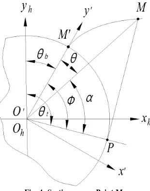
In fig. 3, the cylinder is cut apart through point M, and its cross-section is shown in fig. 4. In this figure, if M´ is the corresponding point of M on the surface of the cylinder; then the curve MM´ shall be the involute teeth profile on the cross-section and the straight line PM shall be the section line of the generating plane. Now if the involute abduction angle at point M is Ф, then the value of Ф shall be
2 2
/
b(
) /
b(
b t t t) /
bEF R
EG
FG
R
R
R
h
R
R
[image:4.595.230.385.360.557.2]φ
=
=
−
=
θ
+
−
−
(8)Fig. 4: Section across Point M
Now if we add formula (6) and (8), formula (3) shall be derived. Similarly, if Rt is +∞ and θb is zero, then the
turning angle of the generating plane (θt) shall be Ф. Thus, the equation of the involute MM´ in the coordinate system o´-x’y’z’ shall be
'
'
'
(sin
cos )
(cos
sin )
0
bb
x
R
y
R
z
φ φ
φ
φ φ
φ
=
−
=
+
=
(9)
' '
' '
'
cos
sin
sin
cos
h b b
h b b
h
x
x
y
y
x
y
z
z
θ
θ
θ
θ
=
+
= −
+
=
L
( 10)
Now bring formula (9) into formula (10), then
(sin
cos
)
(cos
sin
)
11
0
h b t t
h b t t
h
x
R
y
R
z
θ φ
θ
θ φ
θ
=
−
=
+
=
L
Now if we let the coordinate system o1-x1y1z1 move h along axis z in the positive direction, then the equation of the involute teeth surface of the arch cylindrical gear in the coordinate system o1-x1y1z1 shall be
1
1
1
(sin
cos
)
(cos
sin
)
12
b t t
b t t
x
R
y
R
z
h
θ φ
θ
θ φ
θ
=
−
=
+
=
L
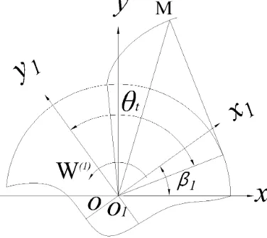
[image:5.595.210.398.368.536.2]As gear 1 rotates along the other gear, if we let the coordinate system o1-x1y1z1 on gear 1 and the coordinate system o-xyz on the rack of gear 1 rotate β1, as shown in fig. 5;
Fig. 5: Rotation of gear 1
Then the following formula shall be derived.
1 1 1 1
1 1 1 1
1
cos
sin
sin
cos
x
x
y
y
x
y
z
z
β
β
β
β
=
−
=
+
=
(13)Thus, the equation of the involute teeth surface of arch cylindrical gear in the coordinate system o-xyz shall be
1 1
1 1
[sin(
)
cos(
)]
[cos(
)
sin(
)]
b t t
b t t
x
R
y
R
z
h
θ β
φ
θ β
θ β
φ
θ β
SIMULATION OF EQUATIONS
Case 1: Simulation of the arc line on the base cylinder
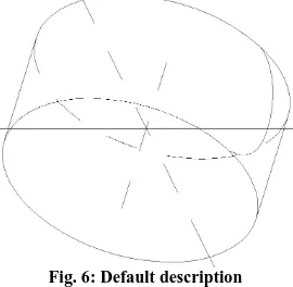
According to formula (7) and formula (6), the simulation of the arc line can be described with the instrument of proeWildfire 5.0. Now if the radius of the cylinder (r) is 20mm and the radius of the arc line (Rt) is 12mm and t is between 0 and 1, then the formula of the equation of the arc line shall be
20
((12 (12 ^ 2
^ 2) ^ 0.5) / 20)
*(180 /
)
10 *
r
theta
z
pi
z
t
=
=
−
−
=
(15)
Now provided that h≤0, let us make a curve with the instrument of proeWildfire 5.0, its appearance (Default) is
[image:6.595.239.374.254.386.2]shown in fig.6 below.
Fig. 6: Default description
Then its appearance (Front) is shown in fig. 7. In this figure, the curve made according to formula (7) does fall on the cylinder.
Fig. 7: Front description
Case 2: Simulation of the teeth surface of the arc cylindrical gear
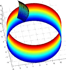
According to formula (12), the simulation of the teeth surface can be described with the instrument of MATLAB R2010a. Now if the radius of the cylinder (r) is 20mm and Rt is 12mm and θt is 1, then the formula of the equation of the teeth surface shall be %% Drawing cylndrical surface code
clear clc close
h=10; %% h is half of the height of the cylndrical surface d=0.12;
[A,Z]=meshgrid(0:2*pi/fix(2*pi/(1.2*d)):2*pi,-h:h/fix(h/d):h); LX=20*cos(A);
clear all
%% Drawing tooth surface code h=[-10:0.3:10];
a=[0:0.1:1]; %% alphabet a take the place of θt [U,V]=meshgrid(h,a);
%%Rt=12 Rb=20
MX=20.*(sin(V)-((sqrt(12.^2-U.^2)-12+20*V)/20).*cos(V)); MY=20.*(cos(V)+((sqrt(12.^2-U.^2)-12+20*V)/20).*sin(V)); surf(MX, MY, U);
[image:7.595.241.383.201.347.2]Now the appearance of the teeth surface is shown in figure 8.
Fig. 8: Simulation of the arc teeth surface
CONCLUSION
The teeth surface of the involute arc cylindrical gear has been established based on the forming principles of the teeth surfaces of the involute spur cylindrical gear and the involute helical cylindrical gear.
The equation of the imprinted curve of the arc line has been derived.
The equation of the teeth surface of the arc cylindrical gear has been derived.
The simulation figures of those equations have been made with the instruments of proeWildfire 5.0 and MATLAB R2010a
Acknowledgments
The authors wish to thank the National Natural Science Foundation of China for contract 51375320, under which the present work was possible.
REFERENCES
[1]AP SONG,WW WU,SH GAO ,Journal Of Shanghai Jiaotong University., 2010,44(12):1735-1740.
[2]SHJ WANG,L HOU,L DONG,Journal Of S1chuan University(Engineering Science Edition)., 2012,44(2):
210-215.
[3]HJ XIAO,L HOU,L DONG,Journal Of S1chuan University(Engineering Science EDITION) .,2013,45(3):
171-175.