ISSN: 1992-8645 www.jatit.org E-ISSN: 1817-3195
3110
A REVIEW OF DIGITAL BREAST TOMOSYNTHESIS
HARD-WARE TECHNIQUES
ABUAJELA ARHUMA GHUMEDH1,S.MASHOHOR 2 , W.A.W ADNAN3 ,ROZI MAHMUD4
1Departmentof Computer and Communication Systems, Faculty of Engineering, Universiti Putra Malaysia,
43400, Selangor, Malaysia
2Department of Computer and Communication Systems, Faculty of Engineering, Universiti Putra Malaysia,
43400, Selangor, Malaysia
3Department of Computer and Communication Systems, Faculty of Engineering, Universiti Putra Malaysia,
43400, Selangor, Malaysia
4Department of imaging, Faculty of Medicine and Health Science, Universiti Putra Malaysia, 43400,
Selan-gor, Malaysia
1[email protected], 2[email protected], 3[email protected], 4[email protected]
ABSTRACT
Digital Mammography (DM) technique is a well-rooted mode of imaging for early breast cancer detection and diagnosis. After the introduction of digital imaging in the field of radiology, several progressive meth-odologies have been developed, specifically tomographic imaging methmeth-odologies that are capable of captur-ing intricate details. The three dimensional (3D) Digital Breast Tomosynthesis (DBT) is one of such meth-odologies which has witnessed extensive penetration in clinics and possesses the capabilities to replace DM for the screening of breast cancer in the future. A lot of pre-acquisition processes of DBT influence its per-formance clinically. Therefore, this research focuses on the comprehensive review of the DBT system hard-ware design, the X-ray supply geometry optimization, radiation dose for breast glandular tissue, X-ray image scatter and breast compression minimization.
Keywords: Digital Breast Tomosynthesis, Acquisition Geometry, Image Acquisition, Radiation Dose, X-Ray Scatter.
1. INTRODUCTION
Standard mammography is a preferred mode of imaging as it is non-invasive, cost-effi-cient and time-efficost-effi-cient. It involves comparatively low, ionising radiation doses, but the Digital Mammography (DM) which has a two Dimen-sional (2D) attribute leads to a superposition of tissues. therefore, imposes two challenges: the de-crease in the visibility of the lesion (impacting sensitivity), found in glandular tissue density po-sitioned below and/or above a lesion, and the ver-tically-separated nature of two or more regular tis-sue structures, seems to be exactly the same as the projection of a lesion (decreasing specificity), both phenomena result in a sensitivity and speci-ficity of 83.5%, and 90.9% respectively for DM
screening [1]. However, for women with dense breasts, these values may be lower [2, 3, 4].
An introduction of digital procurement has enabled improvements in DM. One of the nu-merous issues that are mitigated by digital acqui-sition includes avoidance of the screen-films lim-ited range of linear response. Then again, a 2D projection is obtained from a traditional mam-mography from its corresponding (3D) object, keeping the superposition of breast tissue problem unresolved. The utmost improvement in DM is probably its adjustability. This enables the ad-vancement in imaging methodologies which eliminates some of the constraints of DM.To an-nul the information losses observed in the third dimension, there were two new imaging methodologies developed. They include; Computed
Tomography (CT) image of the breast and dedicated DBT [5, 6, 7, 8, 9, 10, 11]. Although the dedicated breast CT has a lot of potentials, the DBT is presently the most growing technology in the clinical field. It has been approved for clinical use in the United States of America (USA) and across the world (refer to Table I). In DBT, a limited number of X-ray pro-jections are acquired from a narrow angular range
3111 which is statically compressed and a sequence of im-ages are realized with one at either side of the x-ray tube location (Figure. 2). The detector can be fixed or rotates during the acquisitions in order to preserve its top- most surface, which is normal to the x-ray tube [14, 15]. A reconstruction algorithm is imple-mented to process the series of projections acquired. The algorithm uses various locations to project the same tissues so that their vertical position can be cal-culated and thereby the 3D distribution of the tissues can be estimated. As a result of the restricted angle of projection acquisitions, the DBT is distinguished using the anisotropic spatial resolution, with consid-erably low resolution in the perpendicular direction, and the planes which are parallel in direction to the detector, exhibit very large spatial resolution. Fur-ther, the low anisotropic spatial resolution within the depth’s path is considered as adequate in the minimi-zation of the problem of tissue superposition consid-erably, thereby reducing its effect on sensitivity and specificity.
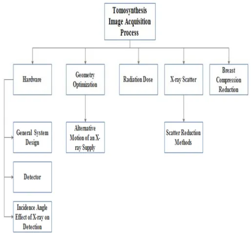
[image:2.612.50.307.397.635.2]Therefore, this paper will review the image acqui-sition methods involved in DBT imaging.
Figure 1: Block Diagram For DBT Pre-Acquisition Processes
2. HARDWARE
2.1 General System Design
At present, the majority of the DBT systems con-stitute of identical elementary modules as digital
mammography systems, which include the arm that holds the x-ray tube, a breast support and compres-sion plate and a direct or indirect complete field digital detector. The transformation of a DM sys-tem into a DBT syssys-tem is achieved through the ad-dition of a specific basic hardware, which is the x-ray tube that has the ability to rotate around a point on or near to the detector, where the detector has a comparatively high-speed readout. More extra modifications have certainly been applied by the manufacturers to ensure that the DBT system ac-quisition is optimized more against the DM acqui-sition, which for instance involves various pixel binning and x-ray spectrum filtration [26, 27]. In recent studies, the researchers have substituted the x-ray tube, as well as the commercial DBT sys-tem’s gantry (Hologic Selenia Dimensions, Incor-porated, Bedford) with a nanotube array made of carbon that spans 370 mm leading to an angular coverage of 30◦ and has 31 x-ray sources. A
devel-oped Modulation Transfer Function (MTF) was yielded by the stationary x-ray source compared to a typical rotating x-ray tube. An improvement in the sharpness of phantom microcalcification im-ages was also observed for the stationary x-ray source. Some of the challenges that are still unre-solved, and needed to improve the overall scan time include exposure time and x-ray tube current, and detector readout rate [28, 29, 30]. The latest version of the photon counting detector is made up of a mechanism of energy resolution, which enables the acquisition of two images simultaneously [32]. In spite of this, the tomosynthesis system cannot ac-quire mammographic images because of the sys-tem’s acquisition geometry. Some research had been conducted on an identical slot scanning pho-ton and its development had been suspended [33]. Table1 provides a summary of the attributes of the various tomosynthesis systems that are presently under pre-clinical or clinical use.
2.2 Detectors
ISSN: 1992-8645 www.jatit.org E-ISSN: 1817-3195
[image:3.612.101.256.271.457.2]3112 on the other hand, it possessed a retribution in the MTF binning path that was aligned to the x-ray’s supply movement. The binned mode further diminished the fall in DQE with reducing expo-sure, which was however comparatively low for the complete resolution mode. In contrast, there was a higher lag, with a binned detector, while for both modes, and the ghosting was insignifi-cant. At the minimum exposure levels, it was fur-ther observed that the DQE compared to DBT re-duction of about 20% only as against the high levels of exposure.
Figure 2: Schematic Of A DBT Acquisition [31]
2.3 Incidence angle effect of X-ray on Detec-tion
Due to the presence of the stationary detector in DBT systems, the x-ray’s angle of incidence onto the detector could be considerably enormous. The out-comes of this enormous angle of incidence over the MTF have been studied analytically, as well as the Monte Carlo (MC) simulations for the direct Sele-nium (Se) detectors, the scintillator-based indirect detectors, and the empirical study of the Point Spread Function (PSF) [37, 38, 39, 40, 41]. Badano et al. first studied the impact over the PSF in the pres-ence of indirect detectors, using MC techniques, where the results of the study revealed the anisotropy presented by the abnormal incidence, and its fluctu-ation all through the surface of the detector, as a re-sult of the variable angle of incidence [42, 43].
3113
Table 1: Specification of clinical of Digital Breast Tomosynthesis systems
DBT systems FUJIFILE Amulet In‐ noyality [16, 17] IMS Giotto TOMO [18, 19] Planmed Nu‐ ance Excel DBT [20, 21] Hologic Selenia Di‐ mension [22] Philips Mi‐ cro‐ Dose [23] Siemens Mammomat Inspiration [22, 24, 25] GE Essential [22]
Filtration 0.7 mm Alu‐
minium (Al) 0.05mm Rho‐ dium (Rh) or 0.05mm Sil‐ ver (Ag) 0.075mm Silver (Ag) or 0.06mm Rhodium (Rh) 0.7mm Alu‐ minium (Al) 0.5mm Al‐ uminium (Al) 0.05mm Rho‐ dium (Rh) 0.03mm Mo‐ lybdenum (Mo) or 0.025mm Rhodium (Rh)
Motion Continuous Step and
shoot
Continuous Continuous Continuous Continuous Step and
shoot
Type Full
field‐ direct amorphous selenium (a‐ se Full field‐direct amorphous (a‐se) Full field‐direct amorphous selenium (a‐ se) Full field‐ direct amorphous (a‐se) Line slit Scan‐ spec‐ tral photon counting silicon (Si) Full field‐ direct amorphous selenium (a‐ se) Full field‐indirect
Size (cm) 24x30 24x30 24x30 24x29 21 line
detectors, each 24cm long 24x30 24x30 Pixel size (1m) 150 (ST binned 2x1)
85 85 70 (binned
2x2) 50 (perpen‐ dicul ar to motion) 85 10
Motion Static Static Rotating
during
ex-posure b Rotating Continuous slit scan Static Static Grid
No No No No No No Yes
Angular range (deg) 40 (HR) 15 (ST)
40 30 15c 11 50 25
Number of Projection
15 13c 15 15 21 25 9
Scan time (s)
9 (HR) 4 (ST)
12 20 3.7 3‐10 25 7
Source to detector distance (cm)
65 68 65 70 66 66.5 66
Detector to center of rotation
distance (cm)
4 2 4.37 0 ‐40 4.7 4
ISSN: 1992-8645 www.jatit.org E-ISSN: 1817-3195
3114 and its fluctuation all through the surface of the de-tector, as a result of the variable angle of incidence [42, 43]. In a subsequent study on the same work, a systematic model was devised for the calculation of the PSF feasible for the indirect detectors under var-ying environments, without executing the CPU-in-tensive MC simulations by Freed et al. The same model was further developed to determine the PSF for direct detectors [44].
[image:5.612.92.263.292.548.2]In this study, these analytical models had been used to understand the dependence of these metrics on the angle of incidence of the x-rays and on the design of the detectors.
Figure 3: Digital Detector In DBT Imaging [36]
It was observed that the backsiilluminated de-tectors were limitedly responsive and susceptible to the incidence angle than the front-illuminated detec-tors, and hence, for DBT imaging, the backside-illu-minated detectors would be more appropriate, be-cause it was less sensitive.
3. GEOMETRY OPTIMIZATION
The acquisition of a DBT image, like most other medical imaging modalities, includes a number of parameter selections. The highly researched param-eter acquisitions in DBT are the ones which play a significant role in defining the acquisition geometry which are the projections covered the total angular
range, the distribution of the projections, and the number of projections. Table I shows the enormous differences in the values of the geometrical parame-ters that are used in the latest tomosynthesis systems. The complexity involved in optimizing these param-eters are indicated by the values presented in the ta-ble. Theoretically, it would be presumed that by aug-menting the projection number and the angular range, the utmost quality of image could be attained. In the end, for different angles of projection, the probability of applying varying tube current expo-sure time and/or allowing a random distribution of the angles of projection intensifies the complexity of the optimization problem over the range of angles. This might also improve the image quality, particu-larly for specific clinical procedures (for example, soft tissue lesion or microcalcification detection) [45, 46]. Maidment et al. conducted a wire-based DBT imaging simulation and visualized a rabbit im-age that possessed a photon-counting DBT system [33]. The objective of this experiment was to inves-tigate the geometrical parameter optimal values that are related to the imaging of the DBT. The wire sim-ulations were carried out devoid of any additional noise. It was observed that increasing the projection number and angular range led to a protocol with an optimal acquisition.After the analysis of the projec-tion number’s impact involved with the DBT set for a second time via the use of clinical images, increas-ing the number of projections to a maximum, re-sulted in improved image quality [25]. In one more study conducted by Ren et al. with the help of a ho-mogeneous phantom. It was observed that augment-ing the projection number for a range of angles and a certain overall dose would result in a minute im-provement in the CNR’s vertical profile. Whereas there was a degradation in the in plane image quality due to the increased number of projections [47].Four various acquisition protocols (the use of 2-2 pixels binning was included in a fifth variation) were also compared in a simulation-based study. By employ-ing a homogeneous background, a monochromatic x-ray beam and three distinctive reconstruction tech-niques conducted by Zhou et al. In this study, the au-thors made use of a Signal-to-Noise Ratio (SNR) for assessing in-plane image quality. While in contrast, for vertical resolution in DBT imaging, the research-ers utilized a typical metric, referred to as an Artefact Spread Function (ASF) [48]. Which is defined in the equation below.
3115 Where Isrefers to the signal mean value of the pixel,
IBGrefers to the background mean value of the pixel,
Z is the current location and Z0 is the in-focus plane’s
[image:6.612.90.299.179.336.2]location. With these metrics, the projections number and maximized range of angles led to an optimized image quality, established by Zhou et al. Ghetti and Sechopoulos further validated
Figure 4: ASF From Simulated DBT Images Acquired With Varying Projection Number And A 600 Range Of
Angles. [49]
the same observation and additionally found that, by augmenting the projection number for each range of angles beyond a limit to reduce the artefacts of the off-focus plane, did not yield improvement or the de-sired result in the vertical resolution infinitely (Fig-ure. 4) [50]. In this study, the author had suggested the “quality factor” metric to analyze these relation-ships. The “quality factor” is a mixture of the vertical resolution and the in-plane image quality, which functions as a metric to correlate the DBT’s image quality and is expressed as:
𝑄𝐹 (2)
Here, CNR refers to a measure of the quality of an in-plane image. ASFwrefers to the ASF’s width. For
example, the z location is the point where the ASF (z) in equation (1) reaches an amount of 0.2. As shown in Figure 4, the angles for the number of pro-jection necessary for attaining a “threshold”, above which there is no more improvement, is considerably low in the vertical resolution for a certain range of an-gles. With a common QF metric, Tucker et al con-ducted a study using x-ray sources with a stationary carbon nanotube and made an identical conclusion on the effect of the range of angles, and the DBT’s projection number [28].
3.1 AlternativeMotion of an X-ray Supply As depicted in Fig. 2, in the designs for standard DBT, the X-ray supply progresses in a plane about
an arc, over the breast that undergoes imaging. Additional designs for DBT have been suggested. Stevens et al introduced a Circular DBT, in which the detector and the X-ray supply moved in a circu-lar plane that was aligned to one another [51]. On the other hand, Zeng et al. recommended combin-ing the DBT acquisition with the acquisition of a CT scan to achieve an enhanced reconstruction quality, where a high rate of resolution DBT image obtained using a standard arc motion, was com-bined with a low rate of resolution CT image, ob-tained through an arc-and-line motion [52]. Xia et al. suggested relocating the X-ray supply in both arcs, which were normal to one another, so that a spherical surface part beyond the imaged object could be encircled [53]. Zhang and Yu also sug-gested this geometry, where the source rotation was combined with the rotation of the detector, and a different way was presented to encompass the spherical surface, which was a succession of curved zigzag lines as shown in Figure. 5 [54]. With the use of the two architectures in tandem, the advantage was that the frequency domain could be sampled more comprehensively, leading to an en-hanced image quality. However, there were poten-tial geometrical issues with the remaining parts of the patient’s body that needed to be examined for these geometries to be effective clinically.
4. RADIATION DOSE
The radiation dose accumulated in the breast’s glandular tissue is a risk of cancer improvement during breast imaging. Hence, the Mean Glandular Dose (MGD) was recommended as
Figure 5: Alternative X-Ray Source Motions For The Acquisition Of DBT Projections [54]
[image:6.612.319.525.506.626.2]ISSN: 1992-8645 www.jatit.org E-ISSN: 1817-3195
3116 representation was generally done very much like the adipose- glandular tissue composition with a skin layer enclosure. In general, the air karma in front of the breast surface acts like a normalising factor for the MGD, which results in a Normalised mean Glan-dular Dose (DgN), expressed as the Mean Glandular
Dose (MgD) per unit mGy air kerma, with a unit of
mGy. To clarify the assessment of the overall MGD in DBT from an entire acquisition, the Relative Glan-dular Dose (RGD) metric was introduced, and it is expressed as in the equation below [55].
𝑅𝐺𝐷 𝛼 (3)
Where (DgN0) (Dg) N(α) refer to the normalised
glan-dular dose values for the angles of projection 0◦ and
α, correspondingly. Hence, under the same environ-ments, α is comparable to the (DgN) for a DM
acqui-sition. With the help of the RGD, the overall (Dg) N
for an entire DBT acquisition can be calculated as follows:
𝐷 𝑁 𝐷 𝑁 . ∑ 𝑅𝐺𝐷 𝛼 𝐷 𝑁 . 𝑁 . 𝜇 (4)
Where N(α) refers to the number of projections
at-tained, and (µRGD) refers to the RGD mean included
in the DBT acquisition, for the angles of projection. If a DBT acquisition leads to a µRGD of unity, then
DgN can be computed by multiplying the applicable
DgN0 by the projection number in the acquisition.
For some specific acquisition environments, such as small overall range of angles, and for a few varying breast sizes and thicknesses, the estimated (µRGD) had
been found to be very close to unity [56].
5. X-RAY SCATTER
In an X-ray image, the addition, as well as the identification of the X-ray image scatter signal, in the captured images lead to a range of effects that in-clude loss of accuracy, dependency on modality, and loss of contrast. In a digital mammogram, the scat-tering of X-ray signals are mitigated by anti-scatter grids utilization that is positioned between a detec-tor, and the breast, that satisfactorily consume scat-tered rays, as well as transfer non-scatscat-tered X-rays. However, anti-scatter frameworks are certainly less impeccable solutions as these include a conse-quential increased dose of X-rays to the breast, in or-der to attain a non-grid signal strength about the de-tector [43, 57, 58]. In DBT, there are two important reasons why the scatter of an X-ray is more im-portant than DM: (i) the changeable comparative X-ray supply’s location with a static detector will cause an acute saturation of the primary X-rays, by the grid at non-zero angles of projection, (ii) the already low exposure available for every projection would be
lowered further due to the inclusion of a grid. In a study conducted on scatter characterisation, the Monte Carlo technique was used by Sechopoulos et al. to compute the Scatter-to-Primary Ratio (SPR), and scatter PSF for different breast definitions, and imaging conditions [59, 60]. In this study, the authors observed that with an increase in the projection angle, the pieces of the PSF scatter across the opposite side to the X-ray tube position expanded, while the tails at the identical side of the X-ray tube position ta-pered. Moreover, as observed in earlier DM results, [58, 61] there was no substantial variance in the PSF scatter with the spectrum of the X-ray, and only a small variance occurred alongside the Breast Glan-dular Fraction (BGF). The study of the SPR led to polynomial-fit equations that were used to find the SPR at the breast’s projection mass centre. The SPR is a glandular fraction of breast thickness and the DBT projection angle. The advantage of this tech-nique as stated by the authors was that, the impact the X- ray scatter had on DBT image quality was clear and substantial, both in mammography and DBT. However, its effect on clinical performance is yet to be investigated [62, 63, 64].
5.1 Scatter Reduction Methods
Correction methods and X-ray scatter reduction can be deemed as advantageous for improving image quality in DBT. Liu et al. suggested one such scatter reduction method that was based on a software method and required no extra hardware [65]. In the recommended approach, after the reconstruction of the DBT breast image, the available voxels in the im-age of the breast that were reconstructed, were linked to a restricted amount of various mixtures of glandu-lar tissues and adipose with calcium. The 3D image was subsequently categorized and put in an MC sim-ulation system in order to analyze and project the dis-tribution of the scatter signal in the projections. However, a rise in noise level was observed as antic-ipated, through the decrease in the overall signal. X-ray scatter correction algorithms based on low-fre-quency scatter signal subtraction from the acquired projections without reducing the scatter quantum noise. it is characterized by increasing noise through a decrease of the overall signal [63, 65]. Feng and Sechopoulos suggested leveraging the scatter distri-bution’s known insensitivity to breast composition, and size to execute a scatter correction based on a model, in order to reduce the computation time re-quired for the patient-peculiar MC simulations [66].
3117 Figure 6: Horizontal Sketch Via The Centre Of A Le-sion In A DBT Reconstructed Slice Indicating A Decrease
In The Values Of The Voxels, As Well As A Contrast Ow-ing To An X-Ray Scatter Existence [62]
executed with a considerable minimization in the mechanical compression of the breast, employed in the course of acquisition when matched to DM. This can inherently minimize the issue of tissue superpo-sition faced in the imaging of planes. The authors’ employed lesion conspicuity for calcifications and masses and then found that there was no significant contrast in the minimized compression, even on changing the exposure parameters, in order to con-tinue with a fixed dose for the breasts. A clinical study was done by Fornvik et al. By acquiring DBT images of patients with partly the force employed in full compression and with full compression, via identical acquisition technique for both [67, 68]. In breast imaging, even though the key reason for breast compression is the minimization of tissue superposi-tion, there are other reasons as well. Other necessary considerations for breast compression include mo-tion artefacts and breast dose, a decrease in the scat-ter signal of an x-ray and a rise in the number of breast tissues in the terrain of view. Therefore, be- fore clinically carrying out DBT with reduced com-pression, it should be confirmed if a reduction in compression force would adversely impact these other factors [69].
6. DISCUSSION:
This paper discusses characteristic of all digital breast tomosynthesis systems that are variable in clinical. It is understandable that parameters of digi-tal breast tomosynthesis imaging that are used in post-processing. Also, the different methods of re-construction were used for each system of tomosyn-thesis. Although the use of objective metrics such as CNR and ASF yield useful comparative information on image quality, they do not provide any absolute
relation to diagnostic quality, for which perception based image quality models are needed. Many re-search have been performed on lots of the acquisi-tion parameters and other physical aspects of DBT image acquisition, such as radiation dose and x-ray scatter. In many aspects, this has resulted a good un-derstanding of the issues, with several different re-search approaches often arriving at similar conclu-sions.
7.1. Radiation dose
Tomosynthesis is a new digital mammography tool, with safe radiation doses within the allowed pa-rameters, that is changing breast cancer diagnosis thanks to its better performance (improved sensitiv-ity and specificsensitiv-ity) in comparison with traditional 2D mammography. Radiation dosage is a major concern for the International Commission on Radiological Protection due to potential risks of ionizing radiation in unauthorized doses. Tomosynthesis is considered a safe procedure as radiation doses it requires are within parameters established by the Mammography Quality Standard. Since its approval for clinical use in 2013, multiple studies have demonstrated that use of synthesized mammography can decrease radiation dose by nearly half, while maintaining the perfor-mance benefits of DBT over FFDM. Although tomo-synthesis lower resolution than FFDM, with 2Ds, cancer detection is preserved and the risks of missing a low-density finding is outweighed by this benefit as well as the decreased dose. Differences in the ap-pearance of the 2Ds image exist and this may require an adjustment period. Future research avenues re-main to optimize the usage of 2Ds.
7.2. X-ray scatter
ISSN: 1992-8645 www.jatit.org E-ISSN: 1817-3195
3118 of accuracy, depending on the method. In mammog-raphy, the x-ray scatter was treated by the use of anti-scattering networks between the breast and the de-tector, which preferentially absorbed scattered x-ray absorption and the transfer of primary (non-scat-tered) x-rays. Therefore, anti-scattering networks are not ideal and include a penalty for increasing the dose to the breast to achieve the same signal at the detector.
Recently, researchers are trying to perform a better evaluation of the clinical impact of the algo-rithm on detection and diagnosis. One of the main disadvantages of most DBT systems is large scat-tered radiation fraction observed at the image recep-tor. For system modelling and optimization or scatter correction or removal, a good understanding of the scatter signal for each of the DBT projections is re-quired.
To increase image quality, an optimal number of projections was achieved at a relatively low number. Other aspects a correction or reduction of the x-ray scatter signal in DBT projection, still necessitate fur-ther research before application in clinical DBT im-aging. The software-based scatter correction algo-rithm on DBT imaging produced measurable im-provement in the image quality of the scatters cor-rection reconstructions. The application of methods to the reconstruction of images also improve the im-age quality, including those actionable findings in a clinical setting.
Current DBT systems, lack x-ray scatter reduc-tion measures, be it in software or hardware. This leads to the inclusion of the entirety of the x-ray scat-ter signal in the tomosynthesis projections, resulting in reconstruction artifacts and reduced contrast. Ac-cording to previously developed a software-based x-ray scatter correction algorithm that when the ac-quired tomosynthesis projections is applied before reconstruction, it shown potential in improving im-age quality.
Finally, the improved accuracy and overall effi-ciency that DBT can provide will enhance radiolo-gists’ performance and improve the patient experi-ence. Future progressive improvements in DBT tech-nology will likely decrease radiation exposure. In practice, women who require extra mammographic views (e.g., technical repeats, implants, or tiled large breasts) were originally not offered in DBT until we obtained the ability to perform synthesized mam-mography. It may help to clarify the issue over whether the adoption of new technical developments is able to improve the effective screening for breast cancer in a population-based context.
8. CONCLUSION
Lot of works on the factors of acquisition have been done and more visible facets of image acquisi-tion in DBT that includes X-ray scattering and radia-tion dose. As a result, the aforemenradia-tioned has brought about a great knowledge of the concerns, with many various investigated methodologies lead-ing to comparable outcomes. This is seen in the max-imum number of projections achieved and the im-proved image quality obtained from the use of a large angular range. Further works are needed to be done in the modification of X-ray scatter signals in DBT projections before it is applied in the clinical domain. 9. ACKNOWLEDGMETt:
I would like to thank Universiti Putra Malaysia (UPM), for providing technical and financial support during this title research under grant number 9665600 and Computer Aided Detection of Breast Cancer using Region Growing in automated 3D Breast Ultrasound.
REFERENCES
[1] B. C. S. Consortium, “Performance measures for 1,838,372 screening mammography examina-tions from 2004 to 2008 by age—based on BCSC data through 2009,” ed, 2015.
[1] K. Kerlikowske, M. Grady, M. Barclay, and V. Ernster, ”and Family His- tory on the Sensitiv-ity of First Screening Mammography,” Jama, vol. 276, 1996.
[2] P. A. Carney, D. L. Miglioretti, B. C. Yan-kaskas, K. Kerlikowske, R. Rosenberg, C. M. Rutter, et al., ”Individual and combined effects of age, breast density, and hormone replace-ment therapy use on the accuracy of screening mammography,” Annals of internal medicine, vol. 138, pp. 168- 175, 2003.
[3] C. M. Kuzmiak, E. B. Cole, D. Zeng, L. A. Tut-tle, D. Steed, and E. D. Pisano, ”Dedicated three-dimensional breast computed tomogra-phy: lesion characteristic perception by radiol-ogists,” Journal of clinical imaging science, vol. 6, 2016.
[4] J. M. Boone, T. R. Nelson, K. K. Lindfors, and J. A. Seibert,”Dedicated breast CT: radiation dose and image quality evaluation,” Radiol-ogy, vol. 221, pp. 657-667, 2001.
3119 [6] B. Chen and R. Ning, ”Cone-beam volume CT
breast imaging: Feasibility study,” Medical physics, vol. 29, pp. 755-770, 2002.
[7] R. L. McKinley, M. P. Tornai, E. Samei, and M. L. Bradshaw, ”Initial study of quasi-mono-chromatic x-ray beam performance for x-ray computed mam- motomography,” IEEE trans-actions on nuclear science, vol. 52, pp. 1243- 1250, 2005.
[8] R. L. McKinley, M. P. Tornai, C. Brzymialkie-wicz, P. Madhav, E. Samei, and J. E. Bowsher, ”Analysis of a novel offset cone-beam com-puted mam- motomography system geometry for accomodating various breast sizes,” Phys-ica MedPhys-ica: European Journal of MedPhys-ical Physics, vol. 21, pp. 48-55, 2006.
[9] K. K. Lindfors, J. M. Boone, T. R. Nelson, K. Yang, A. L. Kwan, and D.
F. Miller,”Dedicated breast CT: initial clinical expe-rience,” Radiology, vol. 246, pp. 725-733, 2008.
[10] W. A. Kalender, M. Beister, J. M. Boone, D. Kolditz, S. V. Vollmar, and
M. C. Weigel, ”High-resolution spiral CT of the breast at very low dose: concept and feasibility considerations,” European radiology, vol. 22, pp. 1- 8, 2012.
[11] J. T. Dobbins III and D. J. Godfrey, ”Digital x-ray tomosynthesis: current state of the art and clinical potential,” Physics in medicine & biol-ogy, vol. 48, p. R65, 2003.
[12] J. T. Dobbins, ”Tomosynthesis imaging: at a translational crossroads,” Medical physics, vol. 36, pp. 1956-1967, 2009.
[13] B. Ren, C. Ruth, J. Stein, A. Smith, I. Shaw, and Z. Jing, ”Design and performance of the prototype full field breast tomosynthesis sys-tem with selenium based flat panel detector,” in Medical Imaging 2005: Physics of Medical Imaging, 2005, pp. 550-562.
[14] J. W. Eberhard, P. Staudinger, J. Smolenski, J. Ding, A. Schmitz, J. Mc- Coy, et al., ”High-speed large angle mammography tomosynthe-sis system,” in Medical Imaging 2006: Physics of Medical Imaging, 2006, p. 61420C. [15] A. Maldera, P. De Marco, P. Colombo, D.
Origgi, and A. Torresin, ”Dig- ital breast tomo-synthesis: Dose and image quality assess-ment,” Physica Medica: European Journal of Medical Physics, vol. 33, pp. 56-67, 2017. [16] A. Rodr´ıguez-Ruiz, M. Castillo, J. Garayoa,
and M. Chevalier, ”Evalua- tion of the tech-nical performance of three different commer-cial digital breast tomosynthesis systems in the clinical environment,” Physica Medica: Euro-
pean Journal of Medical Physics, vol. 32, pp. 767-777, 2016.
[17] S. Vecchio, A. Albanese, P. Vignoli, and A. Taibi, ”A novel approach to digital breast tomosynthesis for simultaneous acquisition of 2D and 3D images,” European radiology, vol. 21, pp. 1207-1213, 2011.
[18] R. Girometti, C. Zuiani, A. Taibi, S. Vecchio, R. Fazzin, and M. Baz- zocchi, ”Diagnostic yield of digital breast tomosynthesis (DBT) vs digital mammography (DM) in assessing breast cancer: A study on surgical speci- mens,” in European Congress of Radiology, Vienna, Austria, 2012.
[19] M. Varjonen, M. Pamilo, P. Hokka, R. Hok-kanen, and P. Stro¨mmer, ”Breast positioning system for full field digital mammography and digital breast tomosynthesis system,” in Medi-cal Imaging 2007: Physics of Medi- Medi-cal Imag-ing, 2007, p. 651036.
[20] R. Van Engen, R. Bouwman, D. Dance, P. Heid, B. Lazzari, N. Marshall, et al., ”Protocol for the quality control of the physical and tech-nical aspects of digital breast tomosynthesis system,” EUREF, European Guidelines for Quality Assurance in Breast Cancer Screening and Diagnosis, 2013.
[21] J. A. Baker and J. Y. Lo, ”Breast tomosynthe-sis: state-of-the-art and re- view of the litera-ture,” Academic radiology, vol. 18, pp. 1298-1310, 2011.
[22] I. Sechopoulos, J. M. Sabol, J. Berglund, W. E. Bolch, L. Brateman, E. Christodoulou, et al., ”Radiation dosimetry in digital breast tomo-synthesis: Report of AAPM Tomosynthesis Subcommittee Task Group 223,” Medical physics, vol. 41, 2014.
[23] S. Young, S. Park, S. K. Anderson, A. Badano, K. J. Myers, and P. Ba- kic, ”Estimating breast tomosynthesis performance in detection tasks with variable-background phantoms,” in Med-ical Imaging 2009: Physics of Med- Med-ical Imag-ing, 2009, p. 72580O.
[24] E. Shaheen, C. Van Ongeval, F. Zanca, L. Cockmartin, N. Marshall, J. Jacobs, et al., ”The simulation of 3D microcalcification clusters in 2D digi- tal mammography and breast tomo-synthesis,” Medical physics, vol. 38, pp. 6659-6671, 2011.
ISSN: 1992-8645 www.jatit.org E-ISSN: 1817-3195
3120 [26] L. Cockmartin, N. W. Marshall, G. Zhang, K.
Lemmens, E. Shaheen,
C. Van Ongeval, et al., ”Design and application of a structured phantom for detection performance comparison between breast tomosynthesis and digital mammography,” Physics in Medicine & Biology, vol. 62, p. 758, 2017.
[27] X. Qian, A. Tucker, E. Gidcumb, J. Shan, G. Yang, X. Calderon-Colon, et al., ”High resolu-tion staresolu-tionary digital breast tomosynthesis us-ing dis- tributed carbon nanotube x-ray source array,” Medical physics, vol. 39, pp. 2090-2099, 2012.
[28] J. Heggie, P. Barnes, L. Cartwright, J. Diffey, J. Tse, J. Herley, et al., ”Position paper: recom-mendations for a digital mammography quality as- surance program V4. 0,” Australasian phys-ical & engineering sciences in medicine, vol. 40, pp. 491-543, 2017.
[29] C. Lee and J. Baek, ”A sphere phantom ap-proach to measure directional modulation transfer functions for tomosynthesis imaging systems,” IEEE transactions on medical imag-ing, vol. 35, pp. 871-881, 2016.
[30] L. T. Niklason, B. T. Christian, L. E. Niklason, D. B. Kopans, D. E. Castleberry, B. Opsahl-Ong, et al., ”Digital tomosynthesis in breast imag- ing,” Radiology, vol. 205, pp. 399-406, 1997.
[31] F. F. Schmitzberger, E. M. Fallenberg, R. Lawaczeck, M. Hemmendorff,
E. Moa, M. Danielsson, et al., ”Development of low-dose photon-counting contrast-enhanced tomo-synthesis with spectral imaging,” Radiology, vol. 259, pp. 558-564, 2011.
[32] A. D. Maidment, C. Ullberg, K. Lindman, L. Adelo¨w, J. Egerstro¨m, M. Eklund, et al., ”Evaluation of a photon-counting breast tomo-synthesis imag- ing system,” in Medical Imag-ing 2006: Physics of Medical ImagImag-ing, 2006, p. 61420B.
[33] J. G. Mainprize, X. Wang, and M. J. Yaffe, ”The effect of lag on image quality for a digital breast tomosynthesis system,” in Medical Im-aging 2009: Physics of Medical ImIm-aging, 2009, p. 72580R.
[34] J. Zheng, J. A. Fessler, and H.-P. Chan, ”De-tector Blur and Correlated Noise Modeling for Digital Breast Tomosynthesis Reconstruction,” IEEE transactions on medical imaging, vol. 37, pp. 116-127, 2018.
[35] J. Zheng, J. A. Fessler, and H.-P. Chan, ”De-tector Blur and Correlated Noise Modeling for Digital Breast Tomosynthesis Reconstruction,” IEEE transactions on medical imaging, 2017.
[36] B. Zhao and W. Zhao, ”Imaging performance of an amorphous selenium digital mammogra-phy detector in a breast tomosynthesis system,” Medical physics, vol. 35, pp. 1978-1987, 2008. [37] J. G. Mainprize, A. K. Bloomquist, M. P. Kempston, and M. J. Yaffe, ”Resolution at oblique incidence angles of a flat panel imager for breast tomosynthesis,” Medical physics, vol. 33, pp. 3159-3164, 2006.
[38] M. Freed, S. Park, and A. Badano, ”A fast, an-gle-dependent, analytical model of CsI detector response for optimization of 3D x-ray breast imaging systems,” Medical physics, vol. 37, pp. 2593-2605, 2010.
[39] R. J. Acciavatti and A. D. Maidment, ”Calcu-lation of OTF, NPS, and DQE for oblique x-ray incidence on turbid granular phosphors,” in In-ternational Workshop on Digital Mammogra-phy, 2010, pp. 436-443.
[40] R. J. Acciavatti and A. D. Maidment, ”Optimi-zation of phosphor-based detector design for oblique x-ray incidence in digital breast tomo-synthesis,” Medical physics, vol. 38, pp. 6188-6202, 2011.adano, I. S. Kyprianou, R. J. Jen-nings, and J. Sempau, ”Anisotropic imaging performance in breast tomosynthesis,” Medical physics, vol. 34, pp. 4076-4091, 2007. [41] M. Rodrigues, S. Di Maria, M. Baptista, A.
Belchior, J. Afonso, J. Venaˆncio, et al., ”Influ-ence of X-ray scatter radiation on image qual-ity in Digital Breast Tomosynthesis (DBT),” Radiation Physics and Chemistry, vol. 140, pp. 300-304, 2017.
[42] A. Badano, M. Freed, and Y. Fang, ”Oblique incidence effects in direct x- ray detectors: A first-order approximation using a physics-based analytical model,” Medical physics, vol. 38, pp. 2095-2098, 2011.
[43] R. M. Nishikawa, I. Reiser, P. Seifi, and C. J. Vyborny, ”A new ap- proach to digital breast tomosynthesis for breast cancer screening,” in Med- ical Imaging 2007: Physics of Medical Imaging, 2007, p. 65103C.
[44] M. Das, H. C. Gifford, and S. J. Glick, ”Evalu-ation of a variable dose acquisition technique for microcalcification and mass detection in digital breast tomosynthesis,” Medical physics, vol. 36, pp. 1976-1984, 2009.
3121 [46] T. Wu, R. H. Moore, E. A. Rafferty, and D. B.
Kopans, ”A comparison of reconstruction algo-rithms for breast tomosynthesis,” Medical physics, vol. 31, pp. 2636-2647, 2004. [47] [49] I. Sechopoulos and C. Ghetti,
”Optimiza-tion of the acquisi”Optimiza-tion ge- ometry in digital tomosynthesis of the breast,” Medical physics, vol. 36, pp. 1199-1207, 2009.
[48] T. Mertelmeier, J. Ludwig, B. Zhao, and W. Zhao, ”Optimization of to- mosynthesis acqui-sition parameters: angular range and number of projections,” in International Workshop on Digital Mammography, 2008, pp. 220- 227. [49] G. M. Stevens, R. L. Birdwell, C. F. Beaulieu,
D. M. Ikeda, and N. J. Pelc, ”Circular tomosyn-thesis: potential in imaging of breast and upper cervical spine—preliminary phantom and in vitro study,” Radiology, vol. 228, pp. 569-575, 2003.
[50] K. Zeng, H. Yu, S. Zhao, L. L. Fajardo, C. Ruth, Z. Jing, et al., ”Digital to- mosynthesis aided by low-resolution exact computed mography,” Journal of computer assisted to-mography, vol. 31, pp. 976-983, 2007. [51] D. Xia, S. Cho, J. Bian, E. Y. Sidky, C. A.
Pelizzari, and X. Pan, ”To- mosynthesis with source positions distributed over a surface,” in Medical Imaging 2008: Physics of Medical Im-aging, 2008, p. 69132A.
[52] J. Zhang and C. Yu, ”A novel solid-angle tomosynthesis (SAT) scanning scheme,” Med-ical physics, vol. 37, pp. 4186-4192, 2010. [53] I. Sechopoulos, S. Suryanarayanan, S.
Vedan-tham, C. D’Orsi, and A. Karellas, ”Computa-tion of the glandular radia”Computa-tion dose in digital tomosyn- thesis of the breast,” Medical phys-ics, vol. 34, pp. 221-232, 2007.
[54] D. Dance, K. Young, and R. Van Engen, ”Esti-mation of mean glandular dose for breast tomo-synthesis: factors for use with the UK, Euro-pean and IAEA breast dosimetry protocols,” Physics in Medicine & Biology, vol. 56, p. 453, 2010.
[55] P. S. Rezentes, A. de Almeida, and G. T. Barnes, ”Mammography grid performance,” Radiology, vol. 210, pp. 227-232, 1999. [56] S. S. J. Feng, C. J. D’Orsi, M. S. Newell, R. L.
Seidel, B. Patel, and I. Sechopoulos, ”X-ray scatter correction in breast tomosynthesis with a pre- computed scatter map library,” Medical physics, vol. 41, 2014.
[57] I. Sechopoulos, S. Suryanarayanan, S. Vedan-tham, C. J. D’Orsi, and A. Karellas, ”Scatter radiation in digital tomosynthesis of the
breast,” Medical physics, vol. 34, pp. 564-576, 2007.
[58] J. Lee, C. H. Lim, J.-W. Park, I.-H. Kim, M. K. Moon, and Y.-K. Lim, ”The Effect of Grid Ra-tio and Material of Anti-scatter Grid on the Scatter- to-primary Ratio and the Signalto-noise Ratio Improvement Factor in Container Scanner X-ray Imaging,” Journal of Radiation Protection and Re- search, vol. 42, pp. 197-204, 2017.
[59] J. M. Boone, K. K. Lindfors, V. N. Cooper, and J. A. Seibert,”Scatter/primary in mammogra-phy: Comprehensive results,” Medical physics, vol. 27, pp. 2408-2416, 2000.
[60] G. Wu, J. G. Mainprize, J. M. Boone, and M. J. Yaffe, ”Evaluation of scatter effects on image quality for breast tomosynthesis,” Medical physics, vol. 36, pp. 4425-4432, 2009. [61] O. Diaz, D. Dance, K. Young, P. Elangovan, P.
Bakic, and K. Wells, ”Es- timation of scattered radiation in digital breast tomosynthesis,” Physics in Medicine & Biology, vol. 59, p. 4375, 2014.
[62] C. Altunbas, B. Kavanagh, T. Alexeev, and M. Miften, ”Transmission characteristics of a two dimensional antiscatter grid prototype for CBCT,” Medical physics, 2017.
[63] B. Liu, T. Wu, R. H. Moore, and D. B. Kopans, ”Monte Carlo simulation of x-ray scatter based on patient model from digital breast tomosyn-thesis,” in Medical Imaging 2006: Physics of Medical Imaging, 2006, p. 61421N.
[64] J. Feng, S. Si, and I. Sechopoulos, ”A software-based x-ray scatter correc- tion method for breast tomosynthesis,” Medical physics, vol. 38, pp. 6643- 6653, 2011.
[65] R. S. Saunders Jr, E. Samei, J. Y. Lo, and J. A. Baker, ”Can compres- sion be reduced for breast tomosynthesis? Monte Carlo study on mass and microcalcification conspicuity in tomosynthesis,” Radiology, vol. 251, pp. 673-682, 2009.
[66] D. Fo¨rnvik, I. Andersson, T. Svahn, P. Tim-berg, S. Zackrisson, and A. TingTim-berg, ”The effect of reduced breast compression in breast tomosyn- thesis: human observer study using clinical cases,” Radiation protection dosimetry, vol. 139, pp. 118-123, 2010.
![Figure 2: Schematic Of A DBT Acquisition [31]](https://thumb-us.123doks.com/thumbv2/123dok_us/8898050.953834/3.612.101.256.271.457/figure-schematic-of-dbt-acquisition.webp)

![Figure 3: Digital Detector In DBT Imaging [36]](https://thumb-us.123doks.com/thumbv2/123dok_us/8898050.953834/5.612.92.263.292.548/figure-digital-detector-in-dbt-imaging.webp)


