http://www.scirp.org/journal/cs ISSN Online: 2153-1293
ISSN Print: 2153-1285
Compact Metamaterial Antenna with High
Directivity for Bio-Medical Systems
Bose Anandhimeena1, Palavesanadar Thiruvalar Selvan2, Singaravelu Raghavan3
1Anna University-University College of Engineering, Dindigul, India
2TRP Engineering College, Tiruchirappalli, India 3National Institute of Technology, Tiruchirappalli, India
Abstract
In this paper, high directive antenna using metamaterial property is presented for wireless medical systems. The antenna is constructed by semi-circular patch and hexagonal closed ring resonator (HCRR). For medical applications such as wireless patient movement monitoring, telemetry and telemedicine, communication devices working at ISM band frequency is needed. Here, the requirement is completed with improved directivity such as 16 dBi. And also impedance matching also achieved with low reflection loss −20 dB. This antenna works for multiple frequency bands (Industrial, Scientific and Medical-ISM 2.45 GHz, WLAN 5.3 GHz and GSM 1.9 GHz) with improved directivity.
Keywords
Double Negative Metamaterial, Back Propagation, Hexagonal Closed Ring Resonators
1. Introduction
Recent years metamaterial, a new design methodology contributes mainly in medical applications such as diagnosis of cancer cells, cancer treatment, patient monitoring, brain signal analysis, communication devices within body and body temperature, blood pressure monitoring etc., In this related works, the reduced size of the antenna is aimed. Metamaterial concepts are mainly focused for size reduction and improving the conventional patch antenna characteristics [1]-[5]. Here, the antenna consists of hex-agonal shape metamaterial resonators at ground plane to reduce the back wave propa-gation which harms patient body tissues.
The proposed antenna is also called as double negative metamaterial antenna because
How to cite this paper: Anandhimeena, B., Selvan, P.T. and Raghavan, S. (2016) Com-pact Metamaterial Antenna with High Di-rectivity for Bio-Medical Systems. Circuits and Systems, 7, 4036-4045.
http://dx.doi.org/10.4236/cs.2016.712334
Received: May 11, 2016 Accepted: May 31, 2016 Published: October 31, 2016
Copyright © 2016 by authors and Scientific Research Publishing Inc. This work is licensed under the Creative Commons Attribution International License (CC BY 4.0).
of negative permittivity as well as negative permeability values present in the antenna. Since the ground plane comprises of hexagonal metamaterials, it may be considered as defective ground structure antenna. Multiband PIFA antenna was designed by Chang et al. [6] which was mainly used for mobile applications (900 MHz and 1900 MHz). Jie et al. [7] developed a monopole antenna for GSM applications such as 850 MHz, 900 MHz and Directive Communications Systems 1710 - 1880 MHz. In [8], Chen et al. designed T-shape microstrip antenna with modified design methodology which works for mul-tiband frequencies. A crescent-shaped wireless antenna was proposed and it covers 1.7 GHz to 3.1 GHz frequency band. In [9], Sung et al. developed L-shaped antenna with modified structure operates at 3.51 GHz frequency band. But the antenna was not fitted to mount on mobile devices. Here, a high directive antenna is proposed with defective ground structure. A hexagonal shape resonator is imported at ground side of antenna in order to reduce the back propagation towards human body.
2. Antenna Design Methodology
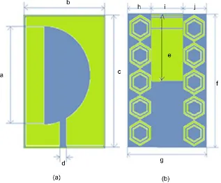
2.1. Antenna SpecificationsThe proposed metamaterial antenna structure is presented in Figure 1. At 1.6 mm thick FR-4 substrate, the HCRR unit cell array is simulated and fabricated. The pro-posed antenna is also printed on a 1.6 mm thick FR-4 substrate of dimensions 35.4 × 27.6 × 1.6 mm3. The antenna is developed with a semi-circular copper conductor at the
[image:2.595.218.535.424.687.2]topside and the HCRR array in the ground plane. The antenna design specifications are listed in Table 1.
Table 1. Antenna dimensions.
Parameters Dimensions in mm Parameters Dimensions in mm
Diameter of the semicircle, a 27.6 Feed width of the antenna, d 1.25 Width of the antenna, b, g 27.6 Length of the gap, e 17.7 Length of the antenna, c, f 35.4 Width of the gap, i 11.6
2.2. Hexagonal Closed Ring Resonators (HCRR)
Hexagonal closed ring resonator (HCRR) is obtained by alternatively placing the metal parts and apertures. HCRR can be excited by incident electric field. HCRR is designed to exhibit negative permittivity and permeability at resonant frequency. HCRR can be placed in either radiating side or non-radiating side of antenna. HCRR loaded ground used for size miniaturization, performance enhancement and also to design beam steerable antenna. HCRR was placed on the non-radiating side to design beam steerable antenna and to control the radiation pattern. Refractive index of the loading part affects the beam direction.
0 2π
kd nd
θ
λ
= = (1)
k—Equivalent wave number, λ0—wavelength of free space, d—unit length in the
propagation direction, n—refractive index.
From Equation (1), it is clear that larger n results in large phase shift, thus larger beam steering angle. HCRR loading part can be used as a phase shifter to achieve beam steering. HCRR provides phase shift to the electro-magnetic fields of the antenna. The cost of the phase shifter that employ solid state devices, micro electromechanical sys-tems structures, ferrite materials, or photo conducting switches is too high to be applied in practice. HCRR loaded ground plane provides low cost solution to design beam steerable antenna.
Metamaterial HCRR are characterised by unit cell test. This is performed by posi-tioning the array structure between two positive and negative ports on x-axis and a transverse electromagnetic (TEM) wave is sent along this waveguide port. At y and z axes, the perfect electric conductor (PEC) boundary and perfect magnetic conductor (PMC) boundary were assigned as shown in Figure 2. Using CST Microwave Studio software, unit cell is simulated in the frequency ranges of 1 - 6 GHz for investigations of metamaterial defective ground structure.
3. Results and Discussion
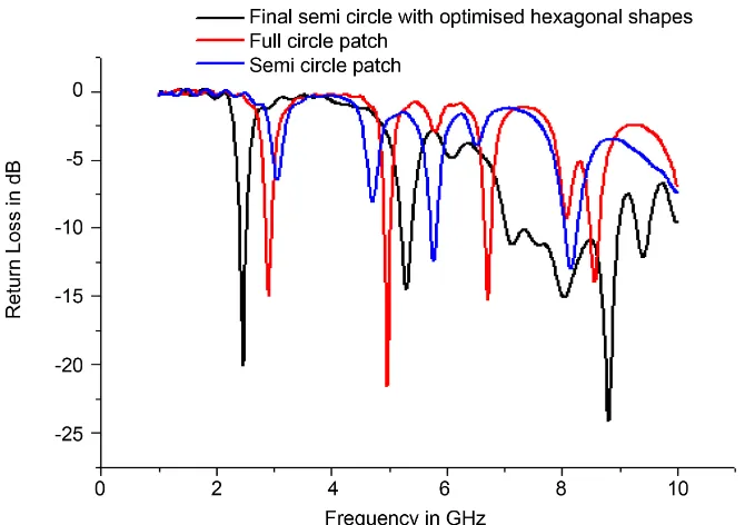
The optimised patch shape, patch position and array size of HCRR are determined as shown in Figures 3-8. The proposed semi-circular patch antenna is simulated for 1 - 10 GHz frequency range.
Figure 2. Unit cell diagram.
[image:4.595.207.542.446.682.2](a) (b)
Figure 3. Patch antenna shape (a) full circle (b) semi-circle.
(a) (b) (c)
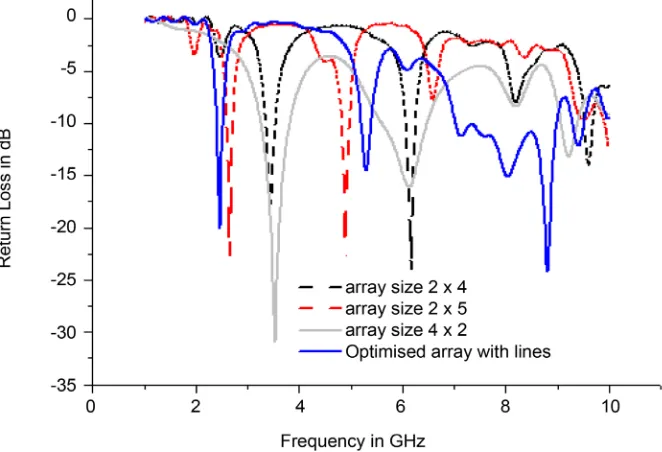
[image:5.595.208.539.252.478.2]Figure 5. Different hexagonal array (a) 2 × 4 (b) 4 × 2 (c) 2 × 5.
Figure 6. Comparison study of array size of hexagonal shape.
[image:5.595.206.545.510.626.2](a) (b) (c)
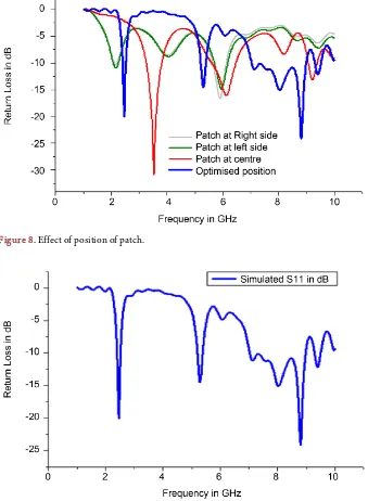
Figure 7. Different position of patch (a) left side (b) right side (c) middle.
Figure 8. Effect of position of patch.
Figure 9. Simulated return loss in dB.
resonator achieves double-negative medium of about 1 GHz at the lower band and about 0.01 GHz at the upper band. The unit cells are arranged in periodic manner so that LC resonator formed.
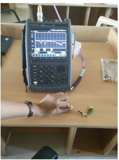
[image:6.595.204.543.79.541.2]Figure 10. Testing set-up.
Figure 11. Measured reflection co-efficient.
SMA connector.
Figure 12. Measured VSWR of proposed antenna.
Figure 13. Directivity of proposed antenna.
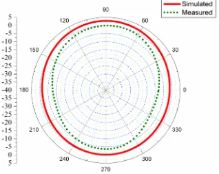
[image:8.595.253.499.487.687.2]radiation pattern is nearly omnidirectional for H field pattern.
In Table 2, it shows that, the proposed antenna with the compact size of 35.4 × 27.6 × 1.6 mm3 has an antenna size at least 83% less than [8], 69% less than [9], and 88% less
than the reference antenna [10] dimension.
4. Conclusion
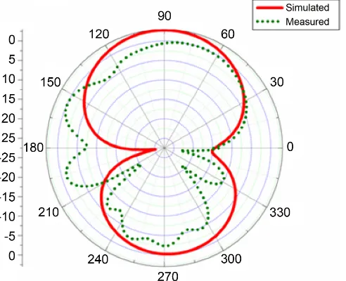
[image:9.595.216.534.285.537.2]The size of the proposed antenna is reduced from reference antenna. The propagation characteristic of directivity is enhanced at the level of 16 dBi. The return loss is also very low (<−20 dB) at 1.9 GHz, 2.45 GHz and 5.3 GHz. Hence, the antenna is suitable for wireless applications GSM, ISM and WLAN. The radiation pattern is measured for 2.45 GHz. In future, reduction of specific absorption rate of the antenna is targeted. This high directive antenna is useful for the measurement of contactless breathing and electroencephalography signals.
Figure 15. Measured H-field pattern at 2.45 GHz.
Table 2. Comparison of reference antennas and proposed antenna.
Antenna Dimensions in mm Directivity in dBi
[1] 37 × 47 Not available
[7] 15 × 26 6
[8] 65 × 40 7
[9] 57 × 37.5 6.4
[10] 60 × 60 5.6
[image:9.595.196.556.587.708.2]Acknowledgements
The acknowledgement is for the valuable suggestions given by Dr. D. Sriram Kumar, Professor and Head ECE, and measurement support by Dr. K. Meena Alias Jeyanthi, Professor ECE, PSNA College of Engg, Dindigul, Tamilnadu, India.
References
[1] Alam, T., Iqbal Faruque M.R. and Islam M.T. (2015) A Double-Negative Metamaterial-In- spired Mobile Wireless Antenna for Electromagnetic Absorption Reduction. Materials, 8, 4817-4828. http://dx.doi.org/10.3390/ma8084817
[2] Islam, M.M., Islam, M.T., Samsuzzaman, M., Faruque, M.R.I., Misran, N. and Mansor, M.F. (2015) A Miniaturized Antenna With Negative Index Metamaterial Based on Modified SRR and CLS Unit Cell for UWB Microwave Imaging Applications. Materials, 8, 392-407.
http://dx.doi.org/10.3390/ma8020392
[3] Wu, B.-I., Wang, W., Pacheco, J., Chen, X., Grzegorczyk, T.M. and Kong, J.A. (2005) A Study of Using Metamaterials as Antenna Substrate to Enhance Gain. Progress Electro-magnetics Research, 51, 295-328. http://dx.doi.org/10.2528/PIER04070701
[4] Lee, H.-M. and Lee, H. (2013) A Metamaterial Based Microwave Absorber Composed of Coplanar Electric-Field-Coupled Resonator and Wire Array. Progress in Electromagnetics Research C, 34, 111-121.
[5] Yahiaoui, R., Chantalat, R., Chevalier, N., Jouvet, M. and Lalande, M. (2013) Metamaterial- Based Highly Directive Antenna: Application in a Monochromatic Wave Radar for a Con-tactless Measurement of The Breathing Activity. Progress in Electromagnetics, Research C, 44, 185-195.
[6] Chih-Hua, C. and Kin-Lu, W. (2009) Printed λ/8-PIFA for Penta-Band WWAN Operation in the Mobile Phone. IEEE Transactions on Antennas Propagation, 57, 1373-1381.
http://dx.doi.org/10.1109/TAP.2009.2016722
[7] Ma, J., Yin, Y.Z., Guo, J.L. and Huang, Y.H. (2010) Miniature Printed Octaband Monopole Antenna for Mobile Phones. IEEE Antennas Wireless Propagation Letters, 9, 1033-1036.
http://dx.doi.org/10.1109/LAWP.2010.2088374
[8] Chen, S.-B., Jiao, Y.-C., Wang, W. and Zhang, F.-S. (2006) Modified T-Shaped Planar Monopole Antennas for Multiband Operation. IEEE Transactions on Microwave Theory and Technology, 54, 3267-3270. http://dx.doi.org/10.1109/TMTT.2006.877811
[9] See, C.H., Abd-Alhameed, R.A., Zhou, D., Lee, T.H. and Excell, P.S. (2010) A Crescent- Shaped Multiband Planar Monopole Antenna for Mobile Wireless Applications. IEEE An-tennas Wireless Propagation Letters, 9, 152-155.
http://dx.doi.org/10.1109/LAWP.2010.2044741
[10] Sung, Y. (2011) A Printed Wide-Slot Antenna with a Modified L-Shaped Microstrip Line for Wideband Applications. IEEE Transactions on Antennas Propagation, 59, 3918-3922.
Submit or recommend next manuscript to SCIRP and we will provide best service for you:
Accepting pre-submission inquiries through Email, Facebook, LinkedIn, Twitter, etc. A wide selection of journals (inclusive of 9 subjects, more than 200 journals)
Providing 24-hour high-quality service User-friendly online submission system Fair and swift peer-review system
Efficient typesetting and proofreading procedure
Display of the result of downloads and visits, as well as the number of cited articles Maximum dissemination of your research work
Submit your manuscript at: http://papersubmission.scirp.org/