2017 International Conference on Electronic and Information Technology (ICEIT 2017) ISBN: 978-1-60595-526-1
A Wideband Array Beamforming Method of Conformal Array
Based by All-pass Digital Filters
Tao-tao GUO
*,1,aand Miao WU
11The 27th Research Institute of CETC, Zhengzhou Henan, 450047 China,
a
*Corresponding author
Keywords: Conformal array antenna, Fractional delay, Digital beam forming
Abstract. In wideband signal beamforming, the traditional phase-shift method causes pattern pointing deviation and sidelobe widening, so the true time delay should be used to compensate the cannel delay accurately. In this paper, in view of the conformal array wideband beamforming of low computational complexity and high delay precision from a real-time processing, it proposes divide the real-time delay into integer and fractional parts. The low-order FIR filter and the high-order FIR filter are cascaded to used to form the digital beam forming device. The simulation result indicates that, the method proposed in this paper can effectively solve the pattern pointing deviation and sidelobe widening problems.
Introduction
The conformal array antenna is an antenna that is conformal to the surface of the carrier. Compared with the traditional planar array antenna, it can overcome the influence of the array antenna on the aerodynamic performance of the carrier platform and obtain the larger effective aperture area of the antenna,thus it plays an irreplaceable role in the airborne, bomb and spaceborne fields, etc [1]. In order to improve the anti-jamming capability of the system, the array antenna usually uses the large instantaneous bandwidth signal. Considering that the conformal array type is more complicated and the relative position between the elements is difficult to be equidistant, the beamforming of the wideband array will be more complexly and difficult to be achieved.
In wideband beamforming, a real-time delay line is required instead of a conventional antenna element phase shifter. In the analog method, the real-time delay line is usually achieved by the waveguide or coaxial cable, but these analog devices exist bulky, power consumption, high cost, by the great influence of temperature of the shortcomings. In the digital method which usually uses dense sampling, time domain interpolation [2] and other methods, but these methods will cause poor delay accuracy and mass data of the shortcomings so that we cannot meet the needs of real-time processing. In [3], the wideband beamforming method with no carrier and very narrow pulse is discussed, but the application is limited. It is described that the method of zero setting the wideband transmission beam based on the LFM signal in [4], but it is not applicable to this paper situation.
Delay Filter Principle
All-pass FIR filter’s amplitude response to all frequencies equal to a constant, after the signal through the all-pass filter the amplitude spectrum remains unchanged, playing the role of pure phase filtering. The impulse response of the filter can be expressed as
sinc i
h(n) = (n - Delay ) (1)
Where Delayi is expressed the delay of i array and reference array. The delay
filter is divided into an integer delay filter and a fractional delay filter, depending on whether the delay is an integer or not.
When Delayi is not an integer, h(n) is non-causal. In practice, usually uses
windowing to achieve it. (Window function can choose rectangular window, Han Ming window, Chebyshev window, etc.) So the impulse response of the fractional delay filter can be expressed as
i
h(n) = Window(n)×sinc(n - Delay ) (2)
Where Window(n) represents the window function. In order to obtain better delay
characteristics, the filter order should be chosen to be about twice the integer part of the delay [5], so the equation (2) is modified as follow
sinc i 0,1,..., (2 )
h(n) = Window(n)× (n - delay - L) n= L (3)
WhereDelay = D + delayi i i,D = round(Delay )i i ,delayi denotes the fractional part
which range is [-0.5, 0.5], andLis half of the filter order.
The order of the filter is fixed as 16th order, the window functions are rectangular
window, Hamming window and Chebyshev window, the fractional delaydelayiis
-0.45, the amplitude-frequency response and the group delay response of the fractional delay filter are shown in Figure. 1 and Figure. 2.
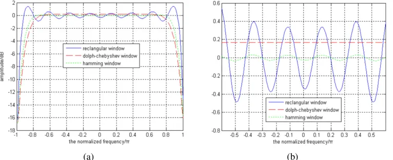
(a) (b) Figure 1. (a) Amplitude frequency response.
[image:2.612.120.503.455.611.2](a) (b)
Figure 2. (a) Group delay characteristics. Figure 2. (b) Group delay characteristics of local amplification.
It can be seen from Figure. 1 that the amplitude-frequency response of the filter with rectangular window truncation fluctuates obviously in the passband when the order of the filters is the same, and it is not suitable for use as a fractional delay filter, where Chebyshev window truncation fluctuating the smallest; from the passband bandwidth, Humming window is better than Chebyshev window. In fact, Hamming window or Chebyshev window’s influence on the beamforming is almost negligible when the wideband beam is forming.
It can be seen from Figure. 2 that when the orders of the filters are the same, similarly, the rectangular window’s filter group delay fluctuation is the largest, and the Chebyshev window’s fluctuation is the smallest. From the linear delay bandwidth, Humming window has the best performance.
In practical application, the selection of the window function should be taken into account synthetically in terms of in-band group delay and linear delay bandwidth.
System Principle
Sub-array Division Principle
The maximum instantaneous bandwidth allowed by the conformal array antenna received signal is not only limited by the antenna beam maximum points to offset, but also to the control of antenna aperture transit time. When the aperture transit time is greater than the reciprocal of the signal bandwidth, for the receiving array, the signal at both ends of the array could not be added at the same time. Therefore, after the
sub-array of the antenna array is divided, the instantaneous bandwidth f of the
signal is limited to
c
sin B
f
L θ
≤ ⋅
(4)
Where L is the antenna aperture, θB is said the antenna maximum scanning
angle, c is the speed of light.
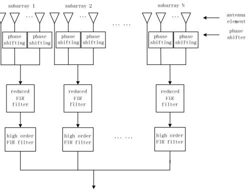
[image:3.612.132.516.66.227.2]beam pointing and scanning of the antenna by combining the phase shift of array element phase shifter and the delay of sub-array delay unit, as shown in Figure 3. By using the structure which is combined with sub-array delay and phase shift, not only it reduces the cost and complexity of the arrays, more importantly, but also partially offsets the aperture transit time, so as to obtains a relatively wide instantaneous signal bandwidth. When the delay value of each delay unit and the phase shift value of each phase shifter are changed, the scanning of the beam in a certain airspace can be completed. It solves the problem of array instantaneous bandwidth limitation and completes the antenna beam scanning. Sub-array division should be taken into account synthetically in the constraints of scanning angle, antenna aperture and signal instantaneous bandwidth.
Figure 3. Realization scheme of the conformal array wideband beamforming.
Principle of the Low-order Filter to Achieve the Digital Delay Line
By the antenna maximum beam angle θB and antenna diameter L can compute the
maximum aperture transit time, let max sin
c
B L
T = × θ , where Fsis for the sampling
rate. We can see the Nmax is the maximum real-time delay that needs to be
compensated. Assuming that the antenna aperture L is 5 m, the antenna beam
pointing angle is 75 ° and the sampling rate is 200 MHz, then Nmax is calculated as
6 max 8
5 sin 75
200 10 3.2198
3 10
N = × × × =
×
(5)
That is, the maximum integer times delay is three sampling periods that needs to be compensated.
The phase response function of the filter is set reasonably so that the group delay
function of the all-pass filter is round(Nmax) sampling periods which needs to be
compensated in the finite frequency band, and round( )i is said to be rounded. The
impulse response of the filter can be expressed as
max
sinc 0,1,..., round( )
h(n) = (n - N) n= N (6)
Where, the possible value of N is
max
restriction on the size of antenna, round(Nmax) will not very large, so it is ok to use the low-order FIR filter to achieve the integer times delay.
Principle of the High-order Filter to Achieve the Fractional Delay
The fractional part of the real-time delay is compensated with a fractional delay filter.
The fractional delay filter is expressed ash(n) =sinc(n - Delay )i , Delayi represents
the fractional part of the i array’s real-time delay. When Delayi is not an integer,
h(n) is non-causal, it is usually implemented by windowing in practice. So the design
of the fractional delay filter’s impulse response is
sinc i 0,1, , 2
h(n) = Window(n)× (n - Delay - M) n = L ×M (7)
Where Window(n) presents the window function. The order of the filter is
2×M+1. The range of the fractional delay
i
Delay is [-0.5, 0.5].
Workflow
The workflow of this device is described as follows:
Step 1: Sub-matrix division;
According to the scanning angle of the conformal array and the required signal bandwidth, the antenna aperture of the divided sub-array is calculated by the equation (4), and then combining the conformal array’s physical shape and computational complexity to divide the sub-array region.
Step 2: Design the low order filter to compensate for integer delay;
Calculate the maximum aperture transit time, calculate the integer part of the real-time delay to be compensated by the equation (5), then the low-order FIR filter that is used to compensate for the integer delay is shown in the equation (6).
Step 3: Design the high order filter to compensate for fractional delay;
According to the delay accuracy requirements to select the appropriate window function and filter order, the high-order FIR filter whose delay range is designed of [-0.5,0.5] that as shown in the equation (7), which to compensate for the real-time delay of the fractional part.
Step 4: Select the reference array to calculate the real-time delay and phase offset
between the arrays.
Select the reference array in the sub-arrays, and compares each array in the sub-arrays with the reference array to calculate the offset phase and make compensation; select the full array-plane reference array, and compares each sub-array with the full array-plane reference array, then calculate the integer delay and fractional delay and make compensation.
System Simulation and Verification
Figure 4. Array patterns comparison.
It can be seen from Figure. 4, in the wideband signal beamforming, if still adopt the method of narrowband beamforming, will cause the main lobe beam broadening and antenna gain decreased, and adopt the wideband beamforming method of this scheme can well meet the demands.
Conclusions
This paper puts forward a scheme of conformal array wideband signal beamforming. The principle and method of the conformal array sub-arrays division are discussed in detail, as well the methods of the delay filter which are used as integer delay and fractional delay. Finally, the paper used an example of the conformal array beamforming to verify the effectiveness of this scheme.
References
[1] Bo Tang, Jun Tang, Meng Tang, Ying-ning Peng, Conformal phase control array signal processing technology research [J]. Aviation Science and Technology, 2009. 5: 36-40.
[2] Quazi A H. An, Overview on the time delay estimate in active and passive systems for target localization [J]. IEEE Trans on Acoust, Speech, Signal Processing, 1981, 29 (3): 527-533.
[3] Min Wang, Shun-jun Wu, Shu-yuan Yang, Time-domain beamforming method of UWB pulse signal [J]. Journal of Radio Science, 2006, 21 (2): 238-243.
[4] Yun-he Cao, Qiang Li, Sheng-hua Wang, etc, The zero point forming method of wideband phased array radar transmit beam [J]. Journal of Xi'an Electronic Technology University: Natural Science Edition, 2006, 33 (3): 395-399.