2016 International Conference on Manufacturing Science and Information Engineering (ICMSIE 2016) ISBN: 978-1-60595-325-0
A Lane Departure Evaluation Algorithm Based
on Static Stable Preview
YANBING BI
ABSTRACT1
According to the LDWS (Lane Departure Warning Systems), of which the universal departure evaluation algorithm is on the hypothesis that both the lateral speed and the turning radius are constant. In this paper, a roadway departure evaluation algorithm is proposed based on the basic static stable preview principle. Firstly the arrived place of vehicle in some future time was anticipated according to the present steady state, and the steady preview was carried on traveling track of vehicle. Then the roadway departure was evaluated based on the deviation of anticipated tracing point from the lateral and the longitudinal distance of roadway. Through the algorithm, the warning precision on vehicle can be largely increased and the happening of nuisance alarm can be well avoided.
INTRODUCTION
Due to the drivers’ decentralization of attraction or mistakes in manipulation, many traffic accidents were caused in the driving road every year. So it is necessary to make quick, precise, and timely warning for drivers before the vehicle is getting into dangerous. Presently, researches on lane warning system home and aboard were mainly evaluation algorithm based on TLC computing. Due to the hypothesis in TLC computing that the both the lateral velocity and the turning radius are constant, which have large differences with the practical vehicle speed and the characteristic of direction control, the error of evaluation result is relatively large. In this paper, a new lane departure evaluation method based on the steady state preview principle was proposed. The steady value of lateral and longitudinal acceleration were applied, which is actually equivalent to directly using a dynamic response model, of whose the control input is step input, as the evaluation model.
1
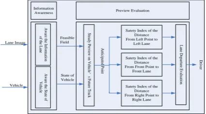
A BRIEF INTRODUCTION TO HYPOTHESIS OF STEADY PREVIEW AND DYNAMIC CORRECTION
The basic content of hypothesis of steady preview and dynamic correction is as following: A driver’s track decision is made absolutely by applying the steady state characteristics in vehicle dynamics to anticipate feasible tracking point, so an ideal expected track decision can be finally made. However, during correction process, it is according to the dynamic response characteristics of vehicle and the lagging features of drivers that the ideal control variable is obtained for correction. Hence, the practical control input can be gotten.
The hypothesis was put forward on the purpose of describing the decision-making behavior of drivers easily, effectively and properly. That is to say, the influences of comprehensive vehicle dynamic characteristics were ignored in track decision-making behavior, and the track is anticipated based on kinematics characteristics of vehicle (namely based on the current motion state of vehicle and the possible acceleration). Thus the research emphasis was placed on the decision-making behavior of ideal expected track pointed. Above all, the hypothesis of steady preview and dynamic correction is actually that the vehicle’s kinematics characteristics is insulated from that of the comprehensive dynamic characteristics, and on the hypothesis that the drivers will make track decision based on the kinematics characteristics of vehicle and proceed manipulation correction according to the dynamic characteristics of vehicle.
L an e D ep ar tu re E va lu ati on
Satety Index of the Distance From Left Point to
Left Lane
Satety Index of the Distance From Front Point to
Front Lane
Satety Index of the Distance From Right Point to
Right Lane S te ad y P re vi ew o n V eh ic le ’ s F ut ur e T ra ck State of Vehicle Feasible Field A w ar e t he In fo rm ati on of th e L an e A w ar e t he S ta te o f V eh ic le Lane Image Vehicle A nt ic ip ate d P oi nt Information
Awareness Preview Evaluation
D
riv
[image:2.612.193.406.424.542.2]er
THE EVALUATION METHOD OF LANE DEPARTURE BASED ON STEADY PREVIEW THEORY
A. Description on the first-order linear model for vehicle speed control characteristics.
In this paper, the local linearization was taken when constructing lane departure decision-making method. That is to say, in a short interval, such as in a 10m s~70m s control cycle, the speed control system of vehicle at current working point and in its fields are approximately described as a linear system, thus the vehicle speed control system can be regarded as a parameter time-varying linear system.
1. The preview time of lane warning system was set at 1.0 ~ 1.5s. During the
preview time, responding to different input of accelerator pedal or brake pedal, the speed changing trend is approximate to a straight line whose nonlinear characteristics are not obvious. Simultaneously, the changing characteristics of longitudinal acceleration are approximate to the response characteristic in a first-order of second-order linear system.
2. The vehicle speed control dynamics system is a strongly nonlinear system, so it is difficult to obtain a good control effect by traditional control methods. It is even difficult to obtain the nonlinear state equation of a controlled system through vehicle dynamics system especially through the dynamics analysis. In most cases, the local equivalent linear method is applied to solve the control problem in nonlinear system.
So, the longitudinal acceleration control characteristics of vehicle can be approximated to a first-order linear reference model. The transfer function is as following:
1
1 nx ax
dx
x T s
s G
T s
Where x represents the practical longitudinal acceleration of vehicle in current time; represents the opening of pedal in current time (the opening of accelerator pedal or the stroke ratio of break pedal). When vehicle is in driving status,
is positive or equals to 0. It represents the throttle opening, and ranges from 0% to 100%. When vehicle is in breaking status,
is negative. It represents the stroke ratio of break pedal and ranges from -100% to 0%. Equation (1) can be used to uniformly depict the two status of vehicle, and then the equivalent linear description model for the speed control characteristic of vehicle. Tnx, Tdx are twodifferential correction constants, and Gax is the static gain of vehicle’s longitudinal
B. The first-order linear model description for the direction control characteristic of vehicle
The direction control characteristic of vehicle refers to the characteristic relation between the angle input from steering wheel and the lateral acceleration output from the practical vehicle. In this paper, the same equivalent linear description method is used to depict the direction control characteristic. The responding description function is constructed:
1 1
ny ay
sw dy
T s y
s G T s
Where y represents the practical lateral acceleration of vehicle in current time;
sw
represents the angle of steering wheel in current time; Tny, Tdy are two system
time constants; Gay is the static gain of vehicle’s lateral acceleration.
C. Parameters Acquisition of Vehicle’s Dynamic Steady Response
Applying the similar method to above, the relation between vehicle’s steady response characteristics and the input of vehicle was constructed. Based on the relation, the steady parameters can be obtained by the input of vehicle. Gax and Gay
can be get through system identification technique. Thus, the steady value of longitudinal acceleration and lateral acceleration can be configured out by the following equation:
ax
ay sw
x G
y G
yx
a v
As to the steady value of yaw rate, it can be estimated by the obtained steady values of lateral acceleration and longitudinal acceleration:
D. Preview on the Future Motion Track of Vehicle
According to the above principle, the preview strategies for anticipating track point are as followings: During preview, based on the theory of rigid kinematics, the possible arrived place of vehicle can be obtained by the steady value of current acceleration xj,yj. The anticipated track point is just the defined future pointPn;
Y0
X0 Y1
X1 Y2
X2 Yn
Xn
The computing of the state of Pn are as followings: The preview time was
divided into several discrete time slices in the same size, then the state of vehicle in each time slice can be computed by the rigid kinematics formulation, and finally the state of vehicle at tTp can be obtained by gradual accumulation. Due to the
influence from the yaw motion of vehicle, the course angle of vehicle was changed among adjacent times. It means that the coordinate system of vehicle varied from time slice to time slice. So it is necessary to carry on coordinate transformation before accumulation.
During computation, the initial coordinate system of vehicle was always used as reference. As shown in Figure 2, the transformation matrix from coordinate system
xn,yn
to coordinate system ( ,x0 y0) is:0 cos sin sin cos j j j j j
A
0 0 j j x x y y
Thus, the state of future point Pj can be obtained from the following calculation
process:
1 1,0 1
j j j
j p
j j j
x x x
A t
y y y
1 1 2
1,0
1 1
1 2
j j j j
p j p
j j j j
x x x x
t A t
y y y y
1
1
j
j j p
j y t x
Where j1, 2, ,J , x0 , y0 represent the initial place of vehicle, x0 , y0
represent the initial lateral acceleration and longitudinal acceleration, x0, y0
represent the steady value of lateral acceleration and longitudinal acceleration , 0
is the initial course angle of vehicle, and Tp is the preview time.
E. Parameter Settings for Dynamic Vehicle Departure Estimation.
According to the vehicle’s obtained anticipated future place, vehicle was simplified as a rectangular rigid body when considering the relative distance from vehicle to lane in this paper. So, the distance from the anticipated track point to lane line can be converted into the distance from corner point to lane line.
In some cases of vehicle’s running along the roadway, or overtaking and lane changing, the nuisance alarm will happen because the distance from vehicle to lane line exceeds the threshold. According to the practical experience, the reason of accidents that vehicle departs from lane are mainly due to driver’s tiredness and carelessness, or the non-ideal condition of forward lane (such as pavement is over dark, the sight line is blocked because of the overcast and rainy day).
lane condition in pointed time segments and the driver’s driving state were considered as parameters to construct a distance threshold of real-time dynamic warning. As proved in investigate, drives will rarely rotate steering wheel when they are tired or careless.
EXPERIMENT AND ANALYSIS
The experimental lane conditions for lane departure evaluation method can be divided into four cases: 1. On the condition of straight line roadway, the departure of vehicle is straight line; 2. On the condition of straight line roadway, the departure of vehicle is crooked; 3. On the condition of crooked roadway, the departure of vehicle is straight line; 4. On the condition of crooked roadway, he departure of vehicle is crooked, as shown in Figure 3-5.
The results show that Through the method proposed in this paper, the happening of nuisance alarm can be largely reduced, and enough time can be spared to drivers to response to the dangerous status. Compared with other algorithms, not only the condition of forward lane but also the previous behaviors of driver were considered as a distance parameter for dynamic departure evaluation in this algorithm. Thus, the responding distance parameter for dynamic departure evaluation can be set according to different drivers.
[image:6.612.101.495.417.504.2]
Figure 3. Depart straightly on straight line road. Figure 4. Depart crookedly on crooked road. Figure 5. Depart straightly on crooked road.
CONCLUSIONS
longitudinal distances from the anticipated track point to roadway were used for lane departure evaluation. All these can largely increase the precise of warning for vehicle.
(2) The sufficient time was spared to drivers to respond to dangerous while the happening of nuisance alarm was reduced simultaneously, which can increase the practicability of warning evaluation algorithm.
(3) The previous behaviors of driver were considered as parameters when setting parameters for warning evaluation, which makes it possible to set warning parameters dynamically based on the state of vehicle and driver. Thus the intelligence of warning algorithm can be improved.
[image:7.612.90.481.255.349.2]
Figure 6. Depart straightly on straight line road. Figure 7. Depart crookedly on crooked road. Figure 8. Depart straightly on crooked road.
REFERENCES
1. Hans Godthelp, Paul Milgram, and Gerard J. Blaauw. The development of a time-related measure to describe driver strategy. Human Factors, 26(3):257-268, 1984.
2. D. J. LeBlanc et al., “CAPC: A Road-Departure Prevention System”, IEEE Control Systems, 1996, 16(6): 61-71.
3. Chen, T. Jochem, and D. Pomerleau, “AURORA: A Vision-Based Roadway Departure Warning Systems”, Proc. Of IEEE IROS95, 1995(8):243-248.
4. Parag H. Batavia. Driver-Adaptive Lane Departure Warning Systems, PhD thesis, Carnegie Mellon University, 1999.
5. Su Khan Lee, Woong Kwon, Jae-Won. Lee, A Vision Based Lane Departure Warning System, Proceedings of the 1999 IEEE/RSJ International Conference on Intelligent Robots and Systems, 0-7803-5184-3/99, 160-165.
6. Konghui Guo and Hsin Guan. Modeling of Driver/Vehicle Directional Control System. Vehicle System Dynamics. 1993, Vol.22:141-184.