2016 3rd International Conference on Information and Communication Technology for Education (ICTE 2016) ISBN: 978-1-60595-372-4
Failure Analysis of Cracking Defect in Engine Cylinder Block
Qiao Lan, Weiwei Wu, Shulin Huang, Yi Yang, Gang Yang
*, Jian Liu
*School of Manufacturing Science and Engineering, Sichuan University, Chengdu, China
Zhengmao Xie, Shangchun Liu
Chongqing Machinery & Electronics Holding Corp Casting Co., Ltd., Chongqing, China
ABSTRACT: This paper presents a study regarding the failure mechanisms in alloyed cast iron engine cylinder block by the analysis of the materials and stress distribution around the crack parts. The results show that abnormal microstructures and the nitrogen inclusions in the crack parts were detected and the stress is tensile stress in the crack parts and leads to a great potential risk of crack initiations. It is suggested that the abnormal microstructures, inclusions and the tensile stress are the main reasons for the formation and propagation of the cracks.
1 INTRODUCTION
Engines have gone through significant changes since the introduction of automobile in the 1880s and have been among the most important inventions in the nineteen century [1]. As one of the core parts in automobile power systems, the quality of engine cylinder block directly determines the service life and safety of engines. The cylinder block acts as the “supporting frame” to install the piston, the crankshaft and other accessories [2-3].An engine cylinder block is subject to several forces that vary in magnitude and direction (multiaxial loading) during working process. Structural complexity and Non-uniform wall thickness of engine cylinder block decided that the cylinder block is liable to fail in various forms during its shaping process [4-8].Once the engine cylinder block was failed, the performance of automobile power unit was affected at best; failure of engine and casualties happened at worst. Consequently, conducting failure analysis to the failed engine cylinder block and avoiding similar accidents from happening again are of greatly important significance and economic benefits in engineering.
2 FAILURE EVENTS
The present paper reports the results obtained on a failure analysis study to investigate the causes of cracking occurred in square holes part of engine cylinder block.
In the process of grinding the surface of engine cylinder block, crack in the square frame was
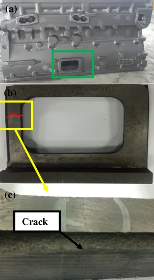
observed. According to survey, similar defects had been found in same part of the engine, accounting for about 2% of all engine cylinder blocks. The cracking was usually found during the last step grinding process, leading the engine cylinder block easily failed and hugely expensive to repair. So, conducting analysis to the cracking defect is indispensable and necessary. Some details about the failed engine cylinder block are as follow: the casting temperature is about 1380-1400℃, and the pouring time is about 28-29s. Bottom gating system was applied to ensure smooth filling of molten metal. And twelve risers were set in the top surface of engine cylinder block to adjust the thermal field of casting. The 3D effect graph of engine cylinder block casting is shown as Figure 1 and the product image is shown as Figure 2.
Figure 2. The production image and the macro profile of crack.
The aim of this work is to study the failure mechanism of cracking in square frame. This type of failure is recurrent among 2000 of produced engine cylinder blocks. This case study includes the following steps: identification of failure mechanism (how did it fail?); determination of causes of failure (why did it fail?); discussion of corresponding factors of failure (what makes it fail?); finally, some recommendations for preventing future failures will be also presented. To study the causes of failure in further, a series of analysis and inspection methods were used. Meanwhile, in order to identify the stress in the process of casting, 3D model of engine
cylinder block in MAGMA software was
implemented with finite difference method. The investigations and tests included the following: Chemical composition analysis
Mechanical properties test
Microstructure observation
Crack evaluation
Fractography
Stress simulation with MAGMA software
3 EXPERIMENTAL INVESTIGATIONS
3.1 Chemical compositions analysis
The chemical compositions of the cracking engine cylinder block are made with HT250 grey cast iron. In order to examine the quality of material, the chemical composition of this material was determined by infrared radiation method (C, S
[image:2.612.99.256.35.321.2]element) and spectroscopy chemical analysis method (other elements). The measured results and recommended standard are shown in Table 1.
Table 1. The measured and recommended chemical compositions of HT250 grey cast iron.
Element C Si Mn P S
ωt(%) Measured
Value 3.27 2.06 0.79 0.017 0.071
Recommend ed Value
3.25-3.
35 1.9-2.1 0.7-0.8 ≤0.06
0.06-0. 1
Element Cr Cu Mo N
ωt(%)
Measured
Value 0.28 0.65 0.26 0.04
Recommend ed Value
0.25-0. 35
0.65-0. 8
0.25-0. 35
≤0.01 3
It can be seen that the composition of the material corresponds to the specified composition range expect more content of N.
3.2 Mechanical properties test
[image:2.612.311.560.103.259.2]To test the mechanical properties of the failed engine cylinder block, one tensile test specimen and two metallographic specimens have been taken from the engine block. The sampling position is shown as Figure 3. It should be mentioned that 1# metallographic specimen is located in cast fillet and is thicker than #2. Meanwhile, Brinell hardness test was performed in one surface of metallographic specimens. Five hardness points were performed in 1# and 2# metallographic specimen.
Figure 3. Schematic diagram of sampling position.
The result of mechanical properties test shows that the tensile strength of HT250 Rm is 158MPa, lower than the recommended mechanical value of engine cylinder block castings (Rm≥224MPa). And the measured hardness values of two specimens are shown in Table 2. According to the test results, all hardness values conform to the recommended standard values.
Table 2. Measured and recommended Brinell hardness values of failed engine cylinder block.
HB 1 2 3 4 5 Recommended
Value (a)
(b)
(c)
[image:2.612.333.539.465.573.2]1# 213 211 213 213 213 187-235
2# 217 217 217 217 217 187-235
3.3 Microstructure observation
1# and 2# specimen were taken from the failed
engine cylinder block for metallographic
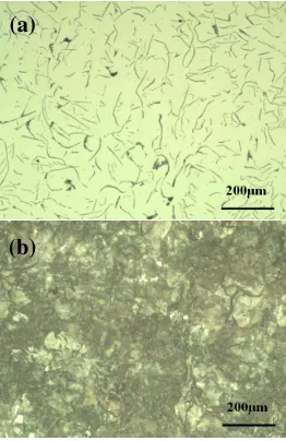
[image:3.612.110.244.196.401.2]investigation. The microstructure observations on various positions were conducted by metallographic microscope. The typical microstructure is shown in Figure 4-5 and evaluated according to the Chinese standard [9], and the observation results are shown in Table 3.
Figure 4. Microstructure of 1# sample (4a: before etching; 4b: after etching).
Figure 5. Microstructure of 2# sample (5a: before etching; 5b: after etching).
Table 3. Observation results of the microstructure.
Metallographic Sample
Graphite morphology
Graphite length
Pearlite amount
1# Flake
(A+E type) 6 98%
2# Flake
(A type) 4 98%
From Figure 4-5 and Table 3, it can be concluded that in the most zones the microstructure is composed of the flake graphite, fine pearlite and a small amount of the ferrite [10].
It should be mentioned that there is a small part of E type flake graphite in the matrix of microstructure. Since the E type flake graphite was short and has the same direction of arrangement, the mechanical property of different direction in engine block may not be consistent (For example, the mechanical properties in the vertical direction may not be as good as the transverse mechanical properties. The tensile test specimen was taken in vertical direction). On the other hand, the tail end of flake graphite has a damage effect to the matrix, especially to the directional E type graphite. These may be the reason for substandard tensile property of specimen.
3.4 Crack evaluation
[image:3.612.111.242.442.644.2]Crack evaluation was conducted by naked eyes and metallographic microscope. The polished and eroded crack sample is shown as Figure 6. As can be seen from Figure 2c and Figure 6 the crack is relatively long and almost penetrate the whole specimen, having a harmful effect to material performance. The typical morphology of cracks in the failed engine cylinder block is shown in Figure 7. The crack is relatively zigzag with little evidence of crack branching. The origin of the crack is associated with the presence of the corner of sample and it propagated to the middle. The propagation of cracks represents an intermittent pattern and there is no evidence of inclusion defect near the crack. Probably, the intermittent one was caused by the steps formed during cracks propagation or another crack source initialized by hard particles like carbide.
Figure 6. Crack sample after being polished and etched. (b)
(a) (a)
[image:3.612.382.490.546.645.2]Figure 7. Morphology of crack.
3.5 Fractography
Fractography was carried out in further and pliers were used to unfold the fracture surface along crack. What calls for special attentions is that fracture surface is easily unfolded. It is not difficult to speculate that the depth of crack is relatively large and the studied sample is extensively affected by crack.
The fractured sample was cleaned in further by ultrasonic cleaner in absolute ethyl alcohol for 30 minutes to remove the remnants on the fractured surface of sample. A low magnification image of the fracture surface of sample is shown in Figure 8.
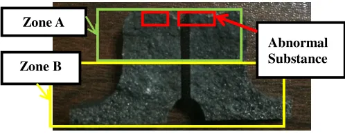
Figure 8. Fracture surface of cracking sample.
It can be seen from Figure 8 the upper zone of fractured sample (Zone A) is flat and gray and there is no obvious metal luster while the lower zone of that (Zone B) appears uneven and silver grey with some metallic luster. According to this phenomenon associated with crack evaluation, it can be speculated that the initiation of crack lies in the Zone A and the crack propagated to Zone B gradually. Meanwhile, some abnormal substance on the top of zone A is also observed, shown in the red marked zone in Figure 8.
To analyze to characteristic of fracture, one fractured sample was detected by SEM in further. Due to the symmetry of fractured samples, the right fractured sample, shown in Figure 8, was selected in this case study and the morphology of the analyzed sample is shown in Figure 9.
As can be seen by SEM, there is some abnormal substance on the side of fracture surface, obviously different from another parts in morphology and color in fracture surface, shown as Figure 9a-9b. On the other hand, obvious oxidation characteristics of fracture can be observed by SEM. For that, there is a little possibility to observe the unbroken and original
morphology of crack initiation. However, it can be roughly deduced by the roughness and the degree of oxidation of fracture that the source of crack lies in the abnormal substance, and propagated to around. Meanwhile, the fracture retains the morphology of molten metal, shown as figure 9d-9e, and the fracture surface is uneven. It indicated in further the crack is the hot one and generated in casting process.
The compositions on the fracture surface were analyzed through EDX attached on to SEM and several characteristic zones marked as A-G, respectively, were analyzed, shown in the red marked zone in Figure 9. Table 4 shows the typical composition analysis result on the surface by the EDX analysis.
Zone A
Zone B
[image:4.612.45.294.327.424.2]Figure 9. Morphology of the fractured sample detected by SEM.
Table 4. Results of energy spectrum analysis in several characteristic zones.
Other than the basic component of the HT250 material, oxygen was found, which may be the results of long-term exposure in the atmosphere or due to the reaction of molten metal with air during casting process. However, one thing worthy to note is that there are relatively large amounts of N element in the abnormal substance, one harmful element needed to be strictly controlled. It could be speculated that the abnormal substance is nitrogen compounds and acts as the initiation of crack when the castings were stressed.
3.6 Stress simulation with MAGMA software
The stress of casting solidification process was simulated by MAGMA software in further. The casting temperature of engine cylinder block is set at 1400℃ and the casting time of that is 29s. The maximum principal stress distribution and the stress distribution in Z axis in section of castings are shown as Figure 10 and Figure 11, respectively, when casting was fully solidified.
Figure 10. Nephogram of maximum principal stress of casting solidification.
Element C O N Ca Ti
ωt(%)
Zone A 1.05 61.49 15.85 1.45 2.26
Zone B 0.94 66.23 30.71 0.67 -
Zone C 1.09 59.90 16.59 2.04 2.64
Zone D 1.23 60.35 31.62 - -
Zone E 0.32 32.92 - - -
Zone F 0.31 30.55 - - -
Zone G 0.31 27.67 - - -
Element Fe Si Mg Cu Mn
ωt(%)
Zone A 10.28 3.26 4.37 - -
Zone B 1.45 - - - -
Zone C 14.83 1.64 - - -
Zone D 3.43 - 1.63 1.74 1.62
Zone E 66.76 - - - -
Zone F 69.14 - - - -
Zone G 72.02 - - - -
[image:5.612.341.532.524.637.2]Figure 11. Nephogram of stress in Z axis of casting solidification.
As can be seen from Figure 10 and Figure 11, the residual maximum principal stress in cracking position is ranging from 72.2Mpa to 96.9Mpa and the stress of Z axial direction in same position is ranging from +69.2Mpa to +95.3Mpa( Positive value presents tensile stress in casting while negative value presents pressure stress). The presence of tensile stress is understandable, because sand core near the cracking position would hinder the casting shrinkage during the cooling process. However, the tensile stress value is still in a reasonable range and not above the standard values of HT250 material in temperature of the end of solidification. It indicates stress factor is not the only factor that causes the casting cracking but it could lead to a great potential risk of crack initiations when associated with other unfavorable factors.
4 ANALYSIS AND DISCUSSION
Casting crack can be classified into two kinds of cracks: the cold crack and hot crack [11-12]. Cold crack refers to the crack generated below the solidus temperature. Generally speaking, cold crack would appear on the surface of the casting. There is a slight oxidation and metallic luster on its fracture. While the hot one is generated near the solidus temperature, for example, the process of solidification. The fracture of hot crack shows serious oxidation without any metallic luster. The hot crack appears along the grain boundary. Consequently, the hot crack is relatively zigzag with little crack branching.
In this case study, it could be speculated that the crack observed is the hot one, according to the propagation trend of crack, the metallic luster and the oxidation degree of fracture surface. Therefore, the casting process of engine cylinder block may play a key role to formation of this crack.
The analysis of the materials shows there is abnormal microstructure (E type flake graphite) in cracking position and nitrogen compounds on fracture surface.
On one hand, E type graphite is
directionally-distributed, which is formed in rapid
cooling conditions and may cause the performance deterioration of material. The presence of E type graphite tends to cause material property anisotropy. Once the stress was applied to the length direction of this graphite, cracking would occur along this graphite. On the other hand, fractography to the crack shows the nitrogen compounds act as initiation of crack and the fracture surface retains morphology of molten metal, which indicated the crack is formed during casting process. The presence of this inclusion tends to cause stress concentration. The compositions of inclusions imply the formation of nitrogen compounds which may be caused by the nonuniformly distributed chemical elements around the crack parts. Crack initiated in the inclusion would propagate around when stress is applied. Therefore, the abnormal material and inclusion may be the main reasons for substandard mechanical properties.
Simulation of MAGMA software to engine cylinder block indicated that there is relatively high tensile stress (ranging from 69.2Mpa to 95.3Mpa) in the cracking zone. Though statistics to the amounts of failed engine cylinder block shows there is low rate of cracking failure events, cracking may occur under the circumstance of the presence of inclusions
like nitrogen compounds and unqualified
microstructure like E type flake graphite. The presence of inclusions like nitrogen compounds leads to the concentration of stress in castings and wrecked the continuity of the base, causing the occurrence of cracking on the condition of tensile stress. So, it could be known that the failure of engine cylinder block is the comprehensive consequences of abnormal microstructure, the presence of inclusions and tensile stress in casting process.
5 CONCLUSIONS
1) The crack of castings is of zigzag and its fractured surfaces is severely oxidized without obviously metallic luster. It indicates that the crack observed is a hot one and generated in casting process.
2) The compositions of inclusions imply the formation of nitrogen compounds which may be caused by the nonuniformly distributed chemical elements around the crack parts.
3) The E type graphite near the cracking is directionally-distributed and tends to cause material property anisotropy. When stress was applied, crack would propagate along this graphite.
4) The failure of engine cylinder block is the
comprehensive consequences of abnormal
microstructure, inclusions and tensile stress in casting process.
[image:6.612.82.267.35.158.2]REFERENCES
[1] Fonte M, Anes V, Duarte P, et al. Crankshaft failure analysis of a boxer diesel motor. Engineering Failure Analysis, 2015, 56:109-115.
[2] Feng S L. Analysis of automobile engine cylinder block casting process. Hot Working Technology, 2015(1):9-10. [3] Qiao Y H, Song C, Wang Z S, et al. Casting process
analysis on engine cylinder block. Hot Working Technology, 2014(7):65-67.
[4] Gao H, Zhao B, Zhao Z, et al. A cluster of inclusions on Al–Si–Cu die casting cylinder block. Engineering Failure Analysis, 2015, 55:370-375.
[5] Zou C, Zhao H, Shao H, et al. Origination of the Gas Leakage in Low Pressure Die Cast Aluminum Alloy Cylinder Head for Engine. Special Casting & Nonferrous Alloys, 2012, 32(5):443-446.
[6] Mao J W, Hou W R, Jiang Z H. Foundry Quality Improvement for Aluminum Alloy Cylinder Block and Head of KV6 Engine. Industrial Engineering & Management, 2009, 14(2):135-138.
[7] Branco C M, Infante V, Brito A S E, et al. A failure analysis study of wet liners in maritime diesel engines. Engineering Failure Analysis, 2002, 9(4):403-421.
[8] Nicoletto G, Konečná R, Fintova S. Characterization of microshrinkage casting defects of Al–Si alloys by X-ray computed tomography and metallography[J]. International Journal of Fatigue, 2012, 41(41):39-46.
[9] GB/T 7216-2009, metallographic test for gray cast iron. [10] Metals hand book: iron and steels, vol.1.9th ed. Metal
park (OH): American Society for Metals; 1978.
[11] Nie W G. Study on formation mechanism of casting cracking. Foundry Engineering, 2010(4):12-15.