2017 3rd International Conference on Artificial Intelligence and Industrial Engineering (AIIE 2017) ISBN: 978-1-60595-520-9
Research on Improving the Reliabil
i
ty of Vision Positioning
System by Deep Learning
Ling-yu WANG
1,2,*, Yuan-yuan ZHOU
2,3and Wen-bo DONG
2,31University of Chinese Academy of Sciences, Beijing 100049, China
2Technology and Engineering Center for Space Utilization, Chinese Academy of Sciences,
Beijing 100094, China
3Key Laboratory for Space Utilization, Chinese Academy of Sciences, Beijing 100094, China
*Corresponding author
Keywords: Convolutional neural networks, Object detection, Image matching, Vision positioning system.
Abstract. Vision positioning system is widely used in robotics, industrial testing, servo control and other autonomous systems. Precise object positioning needs to accurately match the feature key points of the object, so as to solve the object position and attitude precisely. Simple image or feature matching method cannot meet the requirements of both reliability and accuracy for positioning system. Recently, deep learning has aroused widespread concern, Caffe as a framework for deep learning, performs particularly well in image recognition. In this paper, we propose a method of using convolutional neural networks to recognize target in complex scenes, and then to obtain the information of the target position by precise image matching. The experimental results show that the proposed method effectively eliminates the false target recognition and improves the image matching accuracy.
Introduction
In recent years, due to the rapid development of image processing and computer vision, machine vision has been widely used in aerospace, manufacturing, industrial, medical and electronics fields. The most important function of machine vision is to identify and locate the target. The traditional method to localize the target from the image is to directly adopt the precise image matching, but this method does not work well to distinguish the target in a complex background and often leads to a lot of false matching and positioning accuracy decline. With the introduction of high precision matching requirements, researchers begin to study how to obtain high-precision, more reliable image matching results for complex scenes. Keller [1] proposed a high precision rotation angle estimation method based on angular difference function and demonstrated its applicability to rotation estimation; Yoshihiko Mochizuki [2] of Chiba University of Japan proposed a high precision optical flow estimation method to recover a high-resolution image from a low-resolution image and/or image sequence; and the Qingxiong Yang [3] of the University of Illinois proposed a high precision global stereo matching method based on image segmentation. In addition, J Molnár [4] et al. also achieved many results in matching complex scene images and improving the reliability of matching algorithms. He proposed two illumination-robust variational methods based on cross-correlation that are applicable to color and grey-level sequences and robust to brightness and color illumination changes. However, in the complex environment of low brightness, low image resolution and target occlusion, the traditional visual positioning cannot achieve accurate recognition.
solution. With this method, even if the target is blocked or the environment is complex, the method has no mismatch. Here, we use the traditional ORB [5] (Oriented FAST and Robust BRIEF) algorithm to ensure the accuracy of positioning. Experiments show that this method effectively eliminates the target mismatch and improves the precision of image matching.
The paper will first introduce the positioning system, and then introduce the CNN target recognition method and ORB fine matching part, and then analyze and summarize the experimental results.
Visual Positioning System
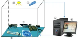
The visual positioning system designed in this paper is shown in Figure 1. The system consists of ①
experimental platform, with complex background, ③ light source, ④ camera and lens, ⑤ host computer with visual processing software, ⑥ display and other components.
The system running mainly includes three steps: image acquisition, image matching and pose solution. Image acquisition is to take image sequence from the camera; image recognition and matching is to obtain the coordinates of the target in the image coordinate system; pose solution is to get the calculate position and attitude information between the target and the camera through the target image coordinates and prior knowledge.
[image:2.612.224.387.370.453.2]The image matching algorithm in this paper is divided into two parts: (1) Using CNN training model to determine whether there is a target in the scene or not, and we analyze the next frame image directly if there is no target. (2) When there is a target, we perform the feature matching between the target and the scene, get the exact position of the target in the image coordinate system. Training is done offline, and the recognition algorithm runs in real time to the host software.
Figure 1. Vision positioning system.
Target Recognition
The target recognition process is as follows: prepare the training set, label the positive and negative samples, use our own data to train, get the model, and then determine whether there is our target in the scene.
Selection of Data Set. In a specific scene, we select 5800 positive samples and 10200 negative samples in different angles and different light shooting. We assign the training set and the test set according to 7: 3. The training set selected 4060 positive samples and 7140 negative samples. The test set selected 1740 positive samples and 3060 negative samples. Figure 2 shows the positive sample set, and Figure 3 shows the negative sample set.
[image:2.612.190.423.618.718.2]Figure 3. Negative sample set.
Before data is imported into the network, the data needs to be preprocessed. Preprocessing includes: (1) Normalization of image size. All images are dimensioned to 256 x 256 pixels before importing the network. (2) Image type conversion. The image data is processed in lmdb format, so that Caffe can use it directly. (3) image mean calculation. Image subtraction of the mean recalculation can improve the training accuracy, and we can generate the mean of the training set by the mean calculation file provided by Caffe.
Model Results. In this paper, the Caffe model is divided into eight layers, five convolution layers and three fully connected layers. In each convolution layer, the excitation function RELU and local response normalized LRN are included, and then down sampling for pooling.
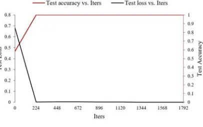
Taking the experimental environment and improve the speed into account, batch_size should not be set too large. In this paper, the batch_size is set to 50 and the training sample has 11200 images, so it takes 224 iterations to complete all the samples once (i.e. epoch). The test sample has 4800 images, batch_size is 50, then it takes 96 times to complete the test once.
Due to the long training time, and to avoid accidental interruption during training, we set the snapshot to 1000, which can store the intermediate results of the training. The loss curve and accuracy curve are shown in Figure 4.
Figure 4. Loss curve and accuracy curve.
When the iterations are 224, the accuracy rate of training is 99.971%, and the error rate of testing is 0.226%. The system basically reaches the steady state. And when the iterations are 9000, the model can basically meet the needs of this experiment.
Precise Matching
After determining the presence of the object in the scene, we perform the feature extraction and matching. Using the world coordinates of the four vertices and the homography matrix, the position and attitude of the target in space is solved.
We define the scene with the object as 1, and without as 0. Using the trained model, if there is no object exists, the program jump out of the loop directly, otherwise process the image matching continuously.
[image:3.612.206.409.395.522.2]In this paper, an image matching method based on ORB operator is adopted. Compared with the commonly used image matching method based on SIFT and SURF, this method uses more efficient feature description and reduces the computational complexity and memory requirements. Besides, it not only improves the efficiency of image matching, but also has good robustness to illumination change, affine transformation and scale scaling.
Feature Matching. In this paper, the ORB algorithm is used to extract the keypoints and feature descriptors of the object. Euclidean distance between the eigenvectors is used to judge the similarity of the feature keypoints, and match the two feature keypoints that satisfy the minimum distance. Then, KNN[8](K-Nearest-Neighbor) matching algorithm is added to match the eigenvector, and judge whether the feature keypoints matched between object are one-to-one mapping, and remove the keypoints that are not satisfied. After that, RANSAC[9](Random Sample Consensus) algorithm is adopted to fit the correct feature keypoints, and solve the homography matrix, establish the corresponding relationship between the feature keypoints.
The homography matrix associates the point set position of the target in the world coordinate system with the point set position of the target in the image coordinate system. Obviously, for this paper, the accuracy of solving the homography matrix to a large extent affectes the accuracy of positioning. To convert the abstraction concept of the homography matrix to a visually visible image, a rectangular box is used to mark the target in the image coordinate system, as shown in green rectangle in the image.
To assure the accuracy of pose positioning, we should verify that the four world coordinates of the object and four image coordinates of the object are one-to-one correspondence. We define the upper left corner of the object placed in the positive direction is No. 0, No. 1, No. 2 and No. 3 by clockwise. The left side of Figure 5 is the object placed in the forward direction; the right side of Figure 5 is the object in the image coordinate system, the blue point represents No. 0, and the red point represents the vertex of No. 1. Figure 5 intuitively shows that the four points we solved are one-to-one correspondence.
[image:4.612.233.379.411.468.2]
Figure 5. The target direction in the corresponding scene.
Experimental Results
To verify the feasibility of this method, we compare the robustness of target recognition and the accuracy of target matching.
Robustness of Target Recognition. We randomly selected 210 positive samples, 90 negative samples, Table 1 shows the comparison between the matching algorithm and the methods of this paper. Positive samples are boxed by a good rectangle, which is called recognition accept; positive samples are not well boxed or the rectangle is false called it recognition inaccurate; positive samples are identified as negative samples or negative samples are identified as positive samples, which is called misrecognized.
Table 1. Contrast of image matching robustness. The number of
recognized images The matching algorithm The method of this paper
recognition accept 174 198
recognition inaccurate 32 12
During the experiment, we find that when the input image pixel size is 256 × 256, the original matching algorithm can not match well, but the convolution neural network that we trained can still accurately identify 210 images. It is obviously that the method of this paper is more robust.
Accuracy of Target Matching. By marking the position of the target in the image coordinate system, we can visually see the exactness of the image matching.
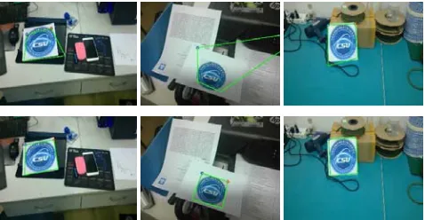
[image:5.612.188.427.203.327.2]When the matching feature keypoints are enough, the first line of Figure 6 is a series of recognition images under the matching algorithm. The second line of Figure 6 is a series of recognition images under our method. The inaccurate matching keypoints appear on the left mainly caused by the interference of nontarget feature keypoints. Compared with the matching graph, we can find that the method of this paper can achieve accurate detection and positioning.
Figure 6. The comparison of image matching when the number of matching feature key points is large.
[image:5.612.187.429.393.518.2]When the matching keypoints are relatively few, the matching algorithm cannot locate the target well, as shown in the first line of Figure 7; the second line of Figure 7 is the corresponding scene, a series of images of our method. It is clear that the method of this paper is more stable.
Figure 7. The comparison of image matching when the number of matching feature key points is small.
Based on the comparison of the two aspects, the system of this paper presents a higher accuracy, and better adapts to the application of complex scenes.
[image:5.612.92.516.666.739.2]To verify the reliability of the method, we use the database of 16000 samples to match, as shown in Table 2, we change the value of Ratio, and get 9 groups (FPR, TPR). The TPR represents true positive rate, and the FPR represents false positive rate. The data corresponding to the traditional method is (FPR1, TPR1), and the data corresponding to our method is (FPR2, TPR2). Among the 16000 tested samples, our method did not have identified negative samples as positive samples, only 10 positive samples were not identified, and the accuracy rate reached 99.83%, the method works well.
Table 2. Contrast of image matching accuracy.
Ratio 0.45 0.50 0.55 0.60 0.63 0.65 0.67 0.70 0.75 TPR1 22.59% 38.74% 53.52% 73.46% 81.92% 86.81% 90.69% 95.69% 99.21%
FPR1 0 0 0 0 0 0 0.04% 0.07% 19.34%
TPR2 99.83% 99.83% 99.83% 99.83% 99.83% 99.83% 99.83% 99.83% 99.83%
FPR2 0 0 0 0 0 0 0 0 0
As shown in Table 2, in the absence of negative samples were identified as positive samples, our method improves the accuracy by 13.02%. In the practical application of the scene, our method has a good reference value.
Conclusion
This paper proposed a method of combining convolutional neural networks with the traditional object detection and positioning. Compared with the traditional object detection and positioning, this paper adds the object detection part before the object positioning, so that the subsequent matching set the higher Ratio, and the corresponding homography matrix is more accurate so that we could use the image coordinates to locate the object position more precisely.
In addition, the proposed method is still accurate when the target is occluded or the environment is complex, so the system is more robust. The experimental results show that the proposed method effectively eliminates the false target recognition and improves the image matching accuracy by 14%.
Acknowledgement
This work is funded by the Manned spaceflight major project. The authors thank Xiaopeng Su and Dongyang Chen for their help on this paper.
References
[1] Keller Y., Shkolnisky Y., Averbuch A. The angular difference function and its application to image registration [J]. IEEE Transactions on Pattern Analysis & Machine Intelligence, 2005, 27(6): 969. Mochizuki Y., Kameda Y., Imiya A, et al. Variational method for super-resolution optical flow [J]. Signal Processing, 2011, 91(7): 1535-1567.
[2] Mochizuki Y., Kameda Y., Imiya A., et al. Variational method for super-resolution optical flow [J]. Signal Processing, 2011, 91(7): 1535-1567.
[3] Yang Q., Wang L., Yang R., et al. Stereo matching with color-weighted correlation, hierarchical belief propagation, and occlusion handling [J]. IEEE Transactions on Pattern Analysis & Machine Intelligence, 2009, 31(3): 492-504.
[4] Molnár J., Chetverikov D., Fazekas S. Illumination-robust variational optical flow using cross-correlation [J]. Computer Vision & Image Understanding, 2010, 114(10): 1104-1114.
[5] Rublee E., Rabaud V., Konolige K., et al. ORB: An efficient alternative to SIFT or SURF [C]// International Conference on Computer Vision. IEEE Computer Society, 2011: 2564-2571.
[6] Rosten E., Porter R., Drummond T. Faster and better: a machine learning approach to corner detection [J]. IEEE Transactions on Pattern Analysis & Machine Intelligence, 2010, 32(1): 105-19. [7] Calonder M., Lepetit V., Strecha C., et al. BRIEF: Binary Robust Independent Elementary Features [C]// European Conference on Computer Vision. Springer-Verlag, 2010: 778-792.
[8] Hastie T., Tibshirani R. Discriminant Adaptive Nearest Neighbor Classification [J]. IEEE Transactions on Pattern Analysis & Machine Intelligence, 1996, 18(6): 607-616.