Surface texture specification, the more complete the better?
Q. Qi
a*, X. Jiang, P.J. Scott and W. Lu
aEPSRC Centre for Innovative Manufacturing in Advanced Metrology, Centre for Precision Technologies, School of Computing and Engineering, Unversity of Huddersfield, Queensgate, Huddersfield, HD1 3DH, UK
Abstract
In this paper, three solutions are proposed to short the surface texture specification without significant information loss. The first solution is operating more default values to simplify the specification without information loss. The second solution is utilizing simple surface texture symbols in CAD systems but affiliated with complete specifications attribute data which can be transferred to other CAx systems or end users for reading and analyzing. The third solution is using both default value and CAD specifications attribute data. After the combination, the shortest specifications can be generated and also can be employed in both paper technical drawings and CAD systems.
1.Introduction
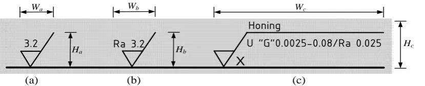
In order to reduce specification uncertainty, the specification of surface texture has became increasingly detailed to provide engineers with optimal information about how to control the manufacturing process and carry out the subsequent required measurement. The latest surface texture specification standard ISO 1302:2002 gives the tools to control the surface texture by an unambiguous specification on technical drawings. This standard makes it possible for the designers to indicate unambiguously the intended surface texture with the least possible effort, also making it possible for the reader of a given surface texture specification to understand, implement or verify the requirement without mistakes [1]. This standard is nowadays applied globally in manufacturing. Most of the engineers are however yet employing its old versions since it is simple and save drawing space despite having significant specification uncertainty (up to 300%) [2]. As shown in Fig 1 and Table 1, the first two versions are short in both vertical and horizontal direction in drawing space; and the 2002 version is much longer in horizontal direction. When ISO 1302:2002 is applied, if there are multiple surface texture symbols or specifications with both upper and lower limit value in a technical drawing, the surface texture symbols, geometric tolerance, dimension, etc., create a congested and almost unreadable technical drawing. It is however with essential meaning if the designers are assigning complete surface texture specifications. Therefore, a dilemma is emerged. Is it the complete the better for the specification of surface texture? On the one side, in order to fulfill the function requirements and control manufacturing process precisely, the specification should be the complete the better. On the other side, if the technical drawing is full of specification symbols, it will turn into an unreadable and un-transferable technical drawing. This issue demonstrates a question that is it possible to simplify a complete surface texture symbol without information loss? In this paper, three solutions are proposed to answer this question. The first solution is utilizing more default values to simplify the symbol. The second solution is exploiting simple surface texture symbols in CAD systems but affiliated with complete specifications attribute data. The proposal of third solution is to overcome the disadvantages of both first and second solutions.
* Corresponding author. Tel.: +44-148447-1284; fax: +44-1484-2161.
Ground
U “G”0.0025-0.8/Rz8max 3.3
X
E10
E1 E2 E3 E4 E5 E6 E7
E9 E8
(a) (b) (c)
Honing
U “G”0.0025-0.08/Ra 0.025
X
Ra 3.2
3.2
Wc
Hc
Hb
Wb
Ha
Wa
Fig. 1. Different versions of the surface texture symbols in technical drawing. (a) the 1971 version, (b) the 1992 version, (c) the 2002 version.
Table 1. Proportions of different symbols in technical drawing
2.First Solution - simplified surface texture specification
There are ten control elements which can be denoted as E1, E2, E3, … E10 respectively in the surface
texture specification defined in ISO 1302:2002, as shown in Fig 2. Each element has different number of options as listed in Table 2. As defined in ISO standards such as ISO 4288 [3], ISO 3274 [4] and ISO 12085 [5], element E1, E2, E3, E5 and E6 have related ISO default values.
The default value of E1 is “U” which is defined in ISO 1302.
The default value of E2 is “Gaussian filter” which is defined in ISO 16610-21 [6].
Defined in ISO 4288 and ISO 3274, the default value of E3 is λc of 0.8mm, then related λs of
[image:2.544.61.476.76.160.2]0.0025mm. For Motif parameters, the default value of A is 0.5mm, B is 2.5mm and λs is 0.008mm.
Fig. 2. Control elements in indication of surface texture requirements on engineering drawings
The default value for E5 of evaluation length as the number of sampling length is “5” which is defined
in ISO 3274.
The default value of E6 is “16%-rule” which is defined in ISO 4288.
No. Standards version Ha(mm) Wa(mm) Height of letters (mm)
a ISO 1302:1971 27 27 8
b ISO 1302:1992 27 32 8
Table 2. Details of control elements
Even when all default values are applied, the indication is however still not sufficiently short. In addition to the ISO default values, there are other elements which probably have national, company, institute or other non-ISO default values. For elements E4 of profile parameter, there are few companies
utilizing Ra, Rz or RSm as default parameters. Depend on the specialized function requirements, particular profile parameter can be assigned as a temporary default value. For E8 of type of manufacturing process,
there is no particular default type. However, for use in the written text, the textual indication for E8-1, E8-2
and E8-3 is APA (any process allowed), MRR (material removal required) and NMR (no material
removed) respectively. To avoid the necessity of repeating a complicated indication a number of times, or where space is limited, or if the same surface texture is required on a large number of surfaces of the workpiece, a simplified reference indication may be invoked [1]. The simplified reference indication is with E8 and a reference letter to refer the specification details. The element E9 of surface texture lay
cannot write by text, then it cannot be simplified except in the simplified reference indication.
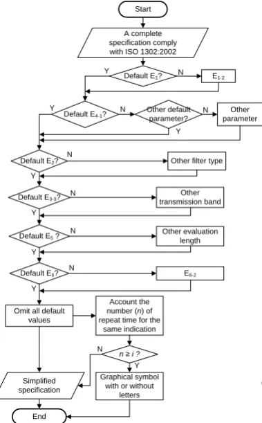
Fig 3 gives the flow chart of the simplified procedure for a complete surface texture specification. The procedure is as follows:
adjudge whether the element E1 is the default value. If yes, goes to the next default judgment,
otherwise the default value is E1-2, then goes to the next default judgment;
adjudge whether the parameter is E4-1. If yes, goes to the next default judgment, otherwise adjudge if
the parameter is other default parameter such as company default one. If yes, goes to the next default judgment, otherwise it is other non-default parameter;
adjudge whether E2, E3, E5 and E6 are default values. If yes, omit all default values, otherwise they are
non-default values;
account the number (n) of repeat time for the same indication;
adjudge n≥i (i is a constant positive integer which is assigned by the designers depend on the drawing space and other situations). If yes, using graphical symbols with or without letter (simplified reference
No. Control elements Value Default value in
ISO standards
Suggested default value E1 Indication of upper(U)
or lower(L) specification limit
E1-1=U,E1-2=L E1-1=U
E2 Filter type E2-1=FPLG,E2-2=FPLS,E2-3 =FPLW... E2-13=F2RC E2-1=FPLG E3 Transmission band E3-1=0.0025-0.08,E3-2=0.0025-0.25 ...E3-5=0.025-8 E3-3=0.0025-0.8
E4 Profile parameter E4-1=Ra,E4-2=Rq,E4-3=Rz… E4-n, n≥62 None Company default parameter E5 Evaluation length as the
number of sampling length
E5-1=3, E5-2=4, E5-3=5…E5-6=8 E5-3=5
E6 Comparison rule E6-1=16%-rule,E6-2=max-rule E6-1=16%-rule E7 Limit value in
micrometers
E7-1=0.025,E7-2=0.05,E7-3=0.1...E7-m, m≥12 None
E8 Type of manufacturing
process E8-1=“ ”, E8-2=“ ”, E8-3=“ ”
None In the written text is APA, MRR and NMR E9 Surface texture lay E9-1=“ ”,E9-2= “=”,E9-3= “X”...E9-7= “P” None
indication), otherwise, goes to simplified specification generation procedure. The simplified specification then will be generated.
This solution is complies with the ISO and company standards; specifications are shorter, and easy for paper technical drawings. Fig 4 gives two examples before and after the simplified procedure, for case (i), the specification is simplified a lot. For complex specifications with both upper and lower specifications with different kind of parameters and limit value (case (ii) in Fig 4), there is no practicable approach to shorten the specification any further.
Start
Default E1? E1-2
Default E4-1?
Default E2?
Default E3-3?
Default E5 ?
Default E6?
Other parameter Other default
parameter?
Other filter type
Other transmission band
Other evaluation length
E6-2
Omit all default values
End
A complete specification comply with ISO 1302:2002
Y N Y N Y N Y N Y N Y N Y N Account the number (n) of repeat time for the
same indication
n ≥ i ?
Graphical symbol with or without
letters Simplified
specification N
[image:4.544.65.255.152.458.2] [image:4.544.257.476.357.456.2]Y
Fig. 3. Flow chart of the simplified procedure for Fig. 4. Examples for complex and simplified symbols a complete surface texture specification
3.Second Solution
The second solution is utilizing simple surface texture symbols in CAD systems and affiliating with complete specifications attribute data which can be transfer to other CAx systems or end users for reading and analyzing. In this solution, a XML based surface texture specifications attribute schema is established.
3.1.XML Schema
Conscious of the difficulty in data exchange among various engineering information systems, the series of ISO 10303 (commonly known as STEP) is for the computer-interpretable representation and
Complex symbols Simplified symbols Honing Ra 0,8
X
Ra 3,1 -2,5/Rz 18 -2,5/Rz 6,5 HoningU “G”0.0025-0.8/Ra 0,8
data exchange between engineering information systems (especially CAx systems). With the increasing popularity of XML on the distributed environment, mapping geometrical specification data into XML seems a logical way to make specifications more accessible and exchangeable [7, 8]. According to the properties of XML Schema and requirements to represent surface texture, this section shows how to represent surface texture specification by using XML Schema to meet different application domains’ requirements. Based on the XML Schema file, users can construct an appropriate XML instance data file to meet requirements. After an XML instance file been constructed by the developers, its validity can be pre-checked with the schema before it is passed to another system. Such an XML instance file can apply to CAx systems, make it more easier to transfer data between different stages of production.
The XML schema for a simplified surface texture indication with a complete specification reference is indicated in Fig 5. For profile surface texture, the first level is the Specification which includes the complete ten elements defined in ISO 1302:2002, the second level is the Symbol which is the simplified surface texture symbol comply with old ISO 1302 version or simplified symbol from first solution.
Profile Surface Texture
Specification
SpecificationType: string FilterType: string
TransmitionBand_ShortWave: decimal TransmitionBand_LongWave: decimal ParameterName: string EvaluationLength: unsignedByte ComparisonRule: string LimitValue: decimal ManufacturingProcess: string IndicationType: unsignedByte
ManufacuringProcessElements: string SpecificationElements: string LayElements: string FontSize: string FontSize: unsignedByte LabelVisible: string LayOrientation: unsignedByte Mode: unsignedByte Zoom: unsignedByte AutoFontSize: string Lay: string
Position: unsignedByte SymbolNumber: unsignedByte symbol
0..1
0..1
[image:5.544.58.279.228.473.2] [image:5.544.294.479.330.470.2]0..1 0..1 0..1 0..1 0..1 0..1 0..1 0..1 0..1 0..1 0..1 0..1 0..1 0..1 0..1 0..1 0..1 0..1 0..1 0..1 0..1 0..1 0..1
Fig. 5. XML schema for surface texture specification. Fig. 6. A case study of second solution applied in AutoCAD.
3.2.CAD attribute data
The complete surface texture specification should be assigned by the designer and a XML file will be generated according to the XML schema in section 3.1. A proposed example of result for second solution applied in AutoCAD is shown in Fig 6. Here, the indication example is a simplified specification from ISO 1302:2002, the complete specification is shown elements by elements in the callout block reference. The related XML file is shown as below:
CAD systems
Designers Complete specifications
Simplified specifications
XML files Simplified
symbols with attribute data
The second solution
The first solution
Technical drawings
Designers Complete specifications
Simplified specifications
Simplified symbols with
list numbers
The second solution
The first solution
Listed related requirements for every symbols <root>
<Specification>
<SpecificationType>U</SpecificationType> <FilterType>Gaussian</FilterType>
<ManufacturingProcess>Milling</ManufacturingProcess>
<TransmitionBand_ShortWave>0.0025</TransmitionBand_ShortWave> <TransmitionBand_LongWave>0.8</TransmitionBand_LongWave> <ParameterName>Ra</ParameterName>
<EvaluationLength>5</EvaluationLength> <ComparisionRule>16%</ComparisionRule> <Limitvalue>0.2</Limitvalue>
<IndicationType>1</IndicationType> <Lay>C</Lay>
</Specification> <Symbol>
<ManufacturingProcessElements>Milling</ManufacturingProcessElements> <SpecificationElements>”Gaussian” 0.0025-0.8/Ra 0.2</SpecificationElements> <FontSize>11</FontSize>
<LabelVisible>True</LabelVisible>
The second solution is easy to transfer and translate by software systems. The procedure is from simplified specification to complete specification, just to the contrary of the first solution. However it can only be applied in CAx systems, not suitable for paper technical drawings.
4.Third Solution
[image:6.544.64.466.479.591.2]As both two solutions have advantages and disadvantages, in order to overcome the disadvantages of both solutions, the third solution is using both default values and CAD specifications attributes data. If the symbol will be draw in CAD system, the assigned complete specification will be simplified firstly by utilizing the first solution. The simplified indication then will be draw in CAD system and original complete specification elements will be added to the indication attribute dada. If it is for a paper technical drawing, the simplified specification will be generated by the first solution, the simplified indications can be draw with list numbers, and the detailed specification elements can be attached in the spare space or attached documents.
After the combination, the possibly shortest specifications can be generated and also can be employed in both paper technical drawing and CAD systems. However, when applied the approach to paper technical drawing, it may not very convenient when all the detailed requirements are showed and there are limited space. The simplified reference indication can be suggested to apply in this situation.
5.Conclusion
This paper proposed three solutions to simplify surface texture specifications without significant information losses. The proposed three solutions are basic images during surface texture specification assignment considering uncertainty issues.
References
[1] ISO 1302, 2002, “Geometrical Product Specifications (GPS) - Indication of surface texture in technical product documentation,” ISO, Geneva, Switzerland.
[2] Bennich P, Nislsen N. 2005 An Overview of GPS, A Cost Saving Tool. http://www.ifgps.com/; 2005.
[3] ISO 4288, 1996, “Geometrical Product Specifications (GPS) – Surface texture: Profile method – Rules and procedures for the assessment of surface texture,” ISO, Geneva, Switzerland.
[4] ISO 3274, 1996, “Geometrical Product Specifications (GPS) – Surface texture: Profile method – Nominal characteristics of contact (stylus) instruments,” ISO, Geneva, Switzerland.
[5] ISO 12085, 1996, “Geometrical Product Specifications (GPS) - Surface texture: Profile method – Motif parameters,” ISO, Geneva, Switzerland.
[6] ISO 16610-21, 2011, “Geometrical Product Specifications (GPS) - Filtration – Part 21: Linear profile filters: Gaussian filters,” ISO, Geneva, Switzerland.