2016 International Conference on Artificial Intelligence: Techniques and Applications (AITA 2016) ISBN: 978-1-60595-389-2
Boundary Condition Simulation for Structural Local
Refined Modeling Using Genetic Algorithm
Zhong ZHANG
1, Wei LIU
2, Ning GUO
2, Hao CHENG
1and Le WANG
2,*1
Science and Technology on Reliability and Environment Engineering Laboratory, Beijing Institute of Structure and Environment Engineering, Beijing, 100076, China
2School of Aeronautics, Northwestern Polytechnical University, Xi’an 710072, China
*Corresponding author
Keywords: Structural local refined modeling, Boundary condition simulation, Genetic Algorithm (GA), Dynamic strength evaluation.
Abstract. Structural dynamic strength evaluation is paid more attentions in aeronautics and astronautics engineering, and the structural local refined modelling technique which can be utilized to precisely calculate the dynamic strains in the critical local sites of the structure is the key issue in the structural dynamic strength evaluation. Firstly, four common methods, i.e. global / local two-step method, substructure method, transition element method and multi-point constraint (MPC) method, used in structural local refined modeling was reviewed. Then, a structural local refined modeling method, which uses simple physical models to simulate the effect of the surrounding structure on the local structure, is proposed based on Genetic Algorithm (GA). Finally, the proposed structural local refined modeling method was illustrated by simulative example of a four edges fixed aluminum rectangular plate.
Introduction
With the rapid development in aeronautics and astronautics engineering, the safety of the complex aeronautics and astronautics structures cannot be satisfied by the traditional static strength based design, and the dynamic strength of such structures to complex dynamic forces must be investigated. Consequently, the structural dynamic strength evaluation was paid more attentions in the field of aeronautics and astronautics engineering in recent years. In the structural strength analysis, strain analysis is base for evaluating the loading capacity, service life, reliability of the structure and performing the optimization design of the structure [1]. Therefore, the structural finite element modeling technique which can be utilized to precisely calculate the dynamic strains is the critical issue in the structural dynamic strength evaluation. However, the global finite element model of the complex aeronautics and astronautics structures built by mesh refinement technique will always have huge elements, and cannot be utilized for common analysis. Meanwhile, the structural damages are always occurred in the local site of the complex aeronautics and astronautics structures, and it is no need to perform the strain analysis using the global model. Consequently, the structural local refined modeling and analysis might be a useful technique for the dynamic strength analysis of the complex aeronautics and astronautics structures.
The Common Methods Used in Structural Local Refined Modeling and Analysis
Structural local refined modeling is one of the multi-scale analysis technique utilized for balancing the precision and efficiency of the calculation, and can be used to obtain the precise results with low computational costs. In the development of the finite element analysis, there are many techniques developed for balancing the precision and efficiency of the calculation, including:
of the three dimensional fracture; Langhe et al. [3] proposed a structural fatigue life evaluation using the global / local two-step method, and demonstrated the advantages of their method by comparing the results calculated using the proposed method and the super element method.
2) Substructure method, i.e., decomposing the complex structure into several simple substructures, and performing the analysis in each substructure. Such as, Li et al. [4] proposed a multi-scale modeling strategy and method for long span bridge based on the substructure method, and fulfilled the multi-scale analysis for the structural damage analysis of the long span bridge; Bao et al. [5] utilized the substructure method to reduce the order of the whole vehicle dynamics model, and obtained the rigid – flexible coupling model for vehicle system dynamic analysis.
3) Transition element method, i.e., connecting the local fine mesh element with the global coarse mesh element using the transition element. Such as, Surana [6] formed a series transition elements using for connecting the shell element and solid element based on reduced integral method, and then proposed the geometrically nonlinear transition element [7] and axial symmetry transition element [8]; according the motion constrains between different degree of freedom, Gong [9] extracted the transition stiffness matrix from the stiffness matrixes of the shell element and solid element, and fulfilled the connection of shell elements and solid elements.
4) Multi-point constraint (MPC) method, i.e. forming the constraints between different degree of freedom using MPC equations, and solving the incoordinate between the different dimensional elements. Such as, McCune et al [10] and Shim et al [11] proposed an MPC equation deduction procedure for connection different elements based on the work reciprocal theorem in the interface; according to the global analysis results of a long span bridge, Li et al. [4] indicated that the multi-scale model using MPC can be utilized to calculate the local thermal stress.
Boundary Condition Simulation Using Genetic Algorithm (GA)
The above four mention methods can be utilized to solve the calculation efficiency for the complex structure analysis. However, the purpose for the dynamic strength analysis of the complex aeronautics and astronautics structure is to obtain the dynamic strain characteristics of the local critical structures, and there is no need to perform the global model analysis using the above methods. Usually, the structural local refined modeling technique can be utilized. In the structural local refined modeling technique, the local structure should be extracted firstly, and then the effect of the surrounding structure on the local structure can be simulated by the equivalent boundaries, finally the local structure model can be formed by the extracted local structure and its equivalent boundaries. Bian [12] proposed a structural local refined modeling technique based on structural dynamic condensation method, and illustrated the high precision of the proposed method using simulative examples. According to the deduction procedure of the method, it can be seen that: 1) the matrix inverse calculation are required, i.e., it is impossible for calculating the model with huge degree of freedom; 2) both the stiffness and mass matrixes of the obtained equivalent boundary are full matrixes, i.e. the obtain equivalent boundary is a mathematic model, and the corresponding physical model cannot be manufactured for experimental validation of the proposed method. To overcome the above shortages of the structural local refined modeling technique, a boundary condition simulation method in which the equivalent boundary are simulated by some simple physical models (such as short beams and short plates) will be proposed in this paper.
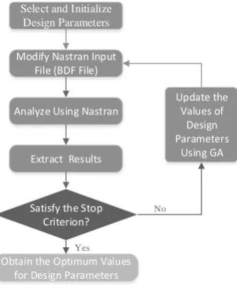
Considering the advantages of GA in optimization and the usage of the commercial finite element analysis software MSC Nastran in aeronautics and astronautics engineering, a boundary simulation method for structural local refined modeling is proposed using both GA and MSC Nastran, the optimization procedure is as follows (shown in Fig. 1):
1) Select and initialize the design parameters in the initial equivalent boundary; 2) Modify the values of design parameters in MSC Nastran input file;
3) Analyze the local structural model using MSC Nastran; 4) Extract the results for constructing the objective function;
5) Output the values of the design parameters if the optimization satisfied the stop criterion; otherwise, update the values of the design parameters using GA and go to step 2).
Select and Initialize Design Parameters
Modify Nastran Input File (BDF File)
Analyze Using Nastran
Extract Results
Obtain the Optimum Values for Design Parameters
Satisfy the Stop Criterion?
Update the Values of
Design Parameters
Using GA
Yes
[image:3.595.213.386.214.422.2]No
Figure 1. Flowchart of boundary condition simulation using GA.
Simulative Example
A four edges fixed aluminum rectangular plate shown in Fig. 2 (a) is adopted to verify the proposed structural local refined modeling method. The dimension of the plate is 800mm*600mm, supposing that the middle dark region with dimension 200mm*150mm is the local critical structure. According to the symmetry of the structure, the dynamic responses of the four particular sites (i.e. Point I, Point II, Point III and Point IV) was utilized to evaluate the precision of the local refine model.
I II III IV
A B
C D
Figure 2. Simulative model.
(a) four edges fixed aluminum rectangular plate, (b) local structure and its boundary conditions simulated by short plates
[image:3.595.110.487.561.729.2]i.e., all the four selected responses calculation points will be the internal points of the local structure. Then, the middle region with dimension 320mm*240mm was selected as the local model, and four short plates with width 80mm were adopted to simulate the boundary conditions, as shown in Fig. 2 (b). In order to increase the calculation precision with the simulative boundary, each short plate was divided by two parts from the middle, and the thicknesses of each plate was selected as the design parameters. Finally, four design parameters (i.e., the thickness of Region A, Region B, Region C and Region D in Fig. 2 (b) were obtained by considering the symmetry of the structure.
As the natural frequency and mode shape are the basic dynamic characteristics, these two characteristics were adopted to form the objective function in the current example, i.e.
N i i N i i i MAC f 1 1 , glo ,loc ( ) | |1 ( )| |
)
(t t t
(1) where, t is the thickness vector which indicates the thicknesses of each short plates, is the natural
frequency, ) ))( ( ) ( ( | ) ( | ) ( , glo , glo , loc , loc 2 , glo , loc i T i i T i i T i i MAC t t t
t is the modal assurance criterion (MAC), is the
[image:4.595.94.504.448.547.2]mode shape, the subscript loc indicate the parameter related with the local refined model, the subscript glo indicate the parameter related with the global model, the subscript i indicate the parameter related with the ith momal, N is the modal order considered in the optimization procedure. Using the objective function formed by the first five natural frequencies and mode shapes, the optimized thicknesses of Region A, B, C and D are updated as 49.1mm, 0.759mm, 1.6mm and 34.7mm, and the optimized modal parameters are listed in Table 1. As shown in Table 1, the maximum error in the natural frequencies is 5.69%, and the MAC values are very close to 1, i.e., the local refined model built by the proposed method can be utilized to obtain the precise results.
Table 1. Optimization results using the first five modes
modal order
natural frequency
MAC value calculated by global
model (Hz)
calculated by local
model (Hz) relative errors
1 98.94 99.28 0.34% 0.9970
2 165.97 169.90 2.37% 0.9964
3 232.73 232.55 0.08% 0.9998
4 276.29 277.36 0.39% 0.9980
5 294.47 277.69 5.69% 1.0000
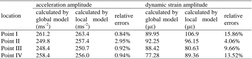
Table 2. Relative errors of the amplitudes of the acceleration and dynamic strain between the local model and global model.
location
acceleration amplitude dynamic strain amplitude
calculated by global model (ms-2)
calculated by local model (ms-2)
relative errors calculated by global model (με) calculated by local model (με)
relative errors
Point I 261.2 263.4 0.84% 89.95 106.9 15.86%
Point II 249.8 257.4 2.95% 92.25 96.15 4.06%
Point III 248.4 250.7 0.92% 88.42 80.63 9.66%
Point IV 258.4 256.0 0.94% 77.28 89.36 13.52%
[image:4.595.96.504.605.702.2]excitation force is set as 1.4*109*sin(80πt) N. The relative errors of the amplitudes of the acceleration and dynamic strain between the local model and global model are listed in Table 2.
It can be seen in Table 2 that the accelerations of the particular points calculated by the local refined model are very close to the results by the global model, but the errors in the dynamic strains are relatively bigger. It is shown that: 1) precise acceleration responses can be obtained using the objective function formed by the natural frequencies and mode shapes; 2) it cannot obtain the precise dynamic strains using only natural frequencies and mode shapes, and some other characteristics should be considered in the construction of the objective function.
Summary
According to the fact that the effect of the surrounding structure on the local structure might be simulated using the equivalent boundary modeled by some simply physical models (such as short beams, short plates), a structural local refined modeling method using Genetic Algorithm was proposed in this paper and illustrated by simulative example of a four edges fixed aluminum rectangular plate. As only the natural frequencies and mode shapes were considered in the modeling procedure, the obtained structural local refined model can only be utilized to calculate the accelerations precisely, and cannot be utilized to achieve the precise dynamic strains. As we known, the dynamic strains are not only related with natural frequencies and mode shapes, but also be related with the damping parameters and structural local features. Then, the future work should be obtain a better modeling procedure for calculating the dynamic strains precisely with the help of the parameters related with dynamic strains.
Acknowledgement
This work was supported by the Innovation Funds of CALT for Universities of China (Grant no. CALT201508) and the Key Laboratory Foundation (Grant no. XX0C93010).
References
[1] M. Z. Tao, Structure design of modern aircraft, Xi’an, Northwestern Polytechnical University Press, 2001.
[2] S. Tanaka, H. Okada, S. Ogawa, S. Okazawa, Analysis of Three-dimensional Crack in Welded Joint Structure using Shell-Solid Zooming Method, Proc. 20th Int. Offshore and Polar Eng. Conf., Beijing, 4 (2010) 31-37.
[3] K. De Langhe, D. Vandepitte, P. Sas, A combined dynamic-static finite element model for the calculation of dynamic stresses at critical locations, Comput. Struct. 65 (1997) 241-254.
[4] Z. X. Li, Z. H. Sun, L. Guo, Concurrent multi scale modeling of structures and damage analyses, J. Southeast Univ. 37 (2007) 251-260.
[5] X. H. Bao, M. R. Chi, Y. H. Lu and F. Yang, Research on vehicle system dynamics model of rigid-flexible mixture based on substructure method, Railway Locomotive and Car 29 (2009) 8-11.
[6] K. S. Surana, Transition finite elements for three-dimensional stress analysis. Int. J. Numer. Meth. Eng. 15 (1980): 991- 1020.
[7] K. S. Surana, Geometrically non-liner formulation for the three dimensional solid- shell transition finite elements. Comput. Struct. 15 (1982) 549-566.
[9] Y. N. Gong, Local/global structural analysis by transition elements, Comput. Struct. 30 (1988) 831-836.
[10] R. W. McCune, C. G. Armstrong, Mixed dimensional coupling in finite element models, Int. J. Numer. Meth. Eng. 49 (2000) 725-750.
[11] K. W. Shim, D. J. Monaghan, C. G. Armstrong, Mixed dimensional coupling in finite element stress analysis, Eng. Comput. 18 (2002) 241-252.