2017 International Conference on Mathematics, Modelling and Simulation Technologies and Applications (MMSTA 2017) ISBN: 978-1-60595-530-8
The Principle and Development of Wind Power
Grounding Design Software
Li XIONG
1, Kai KANG
1, Shao-ping DENG
1, Ming-xin QU
1,
Sheng-li JIANG
1and Yu WANG
21PowerChina Hubei Electric Engineering Corporation, No. 1 Xinqiaosi Road, Jinyinhu Street,
Dongxihu District , Wuhan, Hubei Province of China
2Wuhan AnHaixun Technology Co. Ltd., Wu Da Yuan in East Lake New Technology Development
Zone in Wuhan, Hubei Province of China
Keywords: Wind power plant, Earthing design software, Parameter simulation, Numerical calculation method.
Abstract. The grounding of wind farm should not only meet the demand of power frequency short-circuit current, but also meet the requirements of lightning impulse current. If there are defects in the design of the grounding device of the wind farm, it will result in the consequences of system shock, equipment burning, the suspension of the whole field and even personnel injury. The parameter evaluation of the grounding system of the transformer substation is an important part of the design of power system, and it is very important to carry out accurate and detailed simulation calculation of grounding grid parameters. The wind farm grounding design software developed in this paper mainly adopted numerical calculation method. The software can comprehensively consider the actual influencing factors and come up with the wind farm grounding scheme that conforms to the national standard, which is helpful for the construction of wind farm.
Introduction
The wind power plant covers a small area and is a very promising clean energy. Most of the wind power plant substations are built in hilly terrain, and the soil structure is complex and the grounding resistance is high. The grounding design has been one of the important factors that have troubled the construction, and the grounding fault is also the main factor affecting the operation effect of the wind farm collection line system. It can be seen that the grounding design of wind farm is of great significance[1]. According to the reference [2], the grounding resistance of the grounding device
should be in accordance with: R≤2000/I. Among them, R is the maximum grounding resistance considering the seasonal variation, unit A; I is the ground short-circuit current flowing through the grounding device, unit A. When the grounding resistance of grounding network due to the constraints, such as soil resistivity is higher, and can't expand the grounding network, nor can take advantage of the underground formation, may through the technical and economic comparison, increase the proper grounding resistance, but shall not be greater than 5[3]. Compared with the formula method, the
numerical method can simulate the actual situation better and make the calculation result more accurate. Therefore, the design of the wind farm grounding software based on the numerical calculation method is presented in this paper.
Parameter Calculation Elements of the Grounding Grid
By using the numerical method, the factors which cannot be dealt with by the formula method can be considered comprehensively, such as[4,5]: 1. complex soil models such as layered soil (common
grounding grid, meets the requirements of the grounding calculation of any complex grounding grid; 3. Complex calculation of asymmetrical ground fault current distribution and maximum grounding current; 4. Considering the memory impedance of the grounding conductor and mutual inductance between conductors, and the position of the grounding current on the grounding system; 5. The situation of transient current excitation; 6. Maximum step potential difference and pattern recognition of contact potential difference; 7. Analysis and calculation of space potential, electric field and current density distribution; 8. Optimal design of grounding system; 9. Other condition.
The grounding parameters of the substation include grounding impedance, contact potential difference, step potential difference, mesh potential difference and ground surface potential distribution above the grounding grid. The following three elements need to be considered in the calculation of grounding grid parameters[6,7]: 1. the grounding system including the material
properties of the grounding conductor, the shape and size of the section, the shape, size and the buried depth of the grounding system and grounding conductor lay-out; 2. the resistivity distribution characteristics of the ground system in a wide range of soils; 3. characteristics of current source which is injected into/flows out of the grounding system.
This paper only discusses the numerical processing / solution method of the grounding system ontology, and does not involve the numerical method of soil resistivity and current source. In addition, this paper does not discuss the impact of grounding problems, so the grounding system ontology numerical calculation method is based on the theory of constant current field, that is, when the DC or AC current flows through the grounding system, the potential at any point meets the Poisson/Laplace equation[8]. By dividing the conductors that make up the grounding system into discrete discretization,
the complex integral of the calculated spatial potential is transformed into summation form. By calculating the self-resistance and mutual resistance of the branch after calculating the subdivision, the discharge current distribution of the grounding grid is obtained, and the potential of any point in the space is obtained[9]. The numerical processing / solving method of the grounding system ontology
mainly lies in the solution of the resistance coefficient and the distribution of the discharge current along the grounding system, the calculation accuracy, the calculation complexity, the length of the calculation time and the occupation of the computer memory is the object of the numerical study. At present, with the development of hardware technology, the speed of computer operation and the size of memory are no longer the factors that hinder the application of numerical method[10]. The
numerical method should be improved from the aspects of calculation accuracy and the degree of agreement with the actual situation.
Ground System Ontology Numerical Method
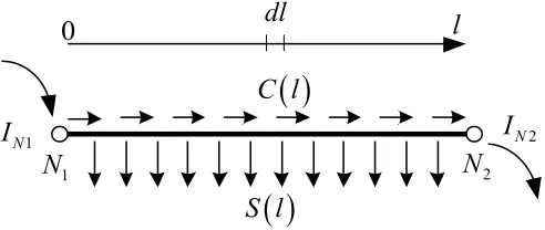
The first step of the grounding system ontology is to divide and disassemble the grounding system, that is, divide the grounding system into a set of nodes and branches. The microscopic branch model is shown in Fig. 1.
S l
l
C l
dl
1
N
I
I
N21
[image:2.612.184.430.568.672.2]N
N
2Figure 1. The microscopic branch model.
In Fig. 1, the branch l connects 2 nodes N1 and N2, and the currents flowing in and out of the nodes
are IN1 and IN2 respectively. Conducted current and scattered current of the branch dl are C(l) and S(l)
medium. Generally, the conductivity or resistivity is used to represent the performance of the soil. The localized range of the grounding system is much smaller than the penetration depth of the AC 50[Hz] or 60[Hz] power frequency current, so the propagation time can be ignored. The characteristics of the grounding system can be analyzed based on the constant current field theory in the case of AC or DC. If the current flows into the grounding device buried in the ground, according to the theory of constant current field, with the infinite point as the reference point, the principle of the Green's function can be used to obtain the potential Vp at any point p:
, .p l
V
S l G p l dl(1) In the equation, G is the Green function. For homogeneous soil, G=ρ/(4)[1/(dp-l)+1/(dp'-l)].
Among them, ρ represents the soil resistivity, d represents the distance, p' represents mirror point. If the Green function G can be theoretically derived, the latter method can also be applied to heterogeneous soils.
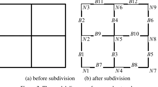
After the split, the grounding system is subdivided into a sufficiently dense branch set R. The meaning of being sufficiently dense is that all branches in R can be approximately equal to S(l) everywhere. The set of two ends of the branch conductor is called node N. The equivalent model of the grounding grid after division is composed of R root branches and N nodes. For example, the model diagram of a ground network is shown in Fig. 2.
1 N 2 N 3 N 4 N 5 N 6 N 7 N 8 N 9 N 1 B 2 B 3 B 4 B 5 B 6 B 7
B B8
9
B B10
11
B B12
[image:3.612.176.440.318.464.2](a) before subdivision (b) after subdivision Figure 2. The model diagram of a ground network.
V(j) is the potential of the j-th node. Since the branch conductor is sufficiently dense, it is assumed that the k-th branch voltage U(k) is constant as the average value of both terminal potential:
.2
V m V n
U k
(2) In Eq. 2, m and n are the Numbers of the two endpoints of k. Eq. 2 is written in matrix form:
.
U KV (3)
In Eq. 3, U is the branch voltage column vector, V is the node voltage column vector, K is the branch - node correlation matrix, when the branch i is connected with node j, K(i, j)=0.5, otherwise it is 0.
Consider all branch voltage and branch flow current I:
1 .
I SU H U (4)
In Eq. 4, S is the tributary array, and H is the mutual resistance matrix of the branch.
,
, d d .i j i j i j
l l
i j G l l l l
R R
H
,
1 . 2 r i b i i b c
IJ
(6) In Eq. 6, the J(b) is the scattered current of the node b; if the node k is connected to the branch i, ci,
b = 1, otherwise it is 0. Eq. 6 is written in matrix form:
.
J K I (7)
In Eq. 7, J is the nodal current column vector, and K′ is the transpose of K. Use the law of current balance:
.
F J YV (8)
In Eq. 8, F is the fault ground current column vector, and Y is the node admittance matrix. Synthesize Eq. 3, Eq. 4, Eq. 7 and Eq. 8:
.
F K SK Y V (9)
The solution equation of the node admittance matrix Y is obtained:
-1
= .
Y AZ A (10)
In Eq. 10, A is a correlation matrix, and when branch k and node j are associated and its direction deviates from the node, then A(j, k) = 1, when branch k and node j are associated and its direction points to node , Then A(j, k) = 1, otherwise it is 0; A′ is the transpose matrix of A. Z is the branch impedance matrix of the ground conductor, whose element is:
i i, i i, i j, j
i j i, , j.Z z ,z M (11)
Among them, M is the external inductance matrix of conductor, M(i, j) is mutual inductance between conductor i and conductor j, z is the self-impedance vector in the conductor, and the internal impedance z(i) of the i-th cylindrical conductor can be expressed as:
0
1 I . 2 I c c c
c c c c
a j j
i
a j a j
z (12)
μc and σc are the permeability and conductivity of conductor i, respectively. a is the radius of
cylindrical conductor. I0 and I1 are the first order of zero order and the first order Bessel function,
respectively.
For the mutual inductance M(i, j) between conductors, according to the electromagnetic field theory, the expressions of mutual inductance M(i, j) are as follows:
0 0,
1 1
, d d = d d cos .
4 li lj i j 4 li lj i j i j
i j l l l l
r r
R R
R RM
(13) In Eq. 13, θi,j is the angle between the conductor i and the conductor j.
Since the injection node current vector F is known, the node voltage vector V can be easily obtained by the Eq. 9, and then the branch voltage vector U and the branch dispersing current vector
I are obtained accordingly, so that the equivalent of the grounding grid Ground impedance Zg and
surface potential distribution Vp and other issues can be solved:
1.
max .
g Z
FV (15).
I SU SKV (16)
, d .l S l G p l l
p R P
V IH
(17) In the Eq. 17, Hp is the mutual resistance matrix of the branch and the observation point, and the
calculation equation of Hp element is the same as Eq. 1.
The cross-step potential difference VS and contact potential VT can be identified by the pattern
recognition of Vp distribution, that is, use
max , cos , sin
S
V Vp x y Vp x y (18)
max max ,
T
V V Vp x y
(19) to identify space coordinates (x, y) and angles . Solve Eq. 18 and Eq. 19, the corresponding result is the position where the maximum cross-step potential difference and the maximum contact potential difference occur.
The above Eq. 1~ Eq. 19 are for the numerical simulation model of the unequal potential of the large-scale grounding system. For the small-scale grounding system, the model can be simplified, that is, assume that the total potential rise of the grounding system is V and ground fault current is F. Apply Eq. 3, Eq. 4 and Eq. 7:
1
1sum sum .
g V Z F
K G K G
(20) Among them, the sum function represents the algebraic sum of all elements of the matrix. Eq. 20 is the result of equipotential method after the grounding system is divided. In the limit case, if the branch is differentiable, then Eq. 20 can be rewritten as an integral form.
1 . 1 d d , i j g i j i j V Z F G
(21) In Eq. 21, is a set of subdivision elements of the grounding system, and it can be a collection of arbitrary lines, faces and bodies. If Eq. 1~ Eq. 19 is rederived using the idea of unequal potential, the calculation method of mutual resistance, conduction impedance and mutual inductance can be updated.Software Development
DXF data interface module CAD editing module of grounding system
Step / contact potential difference analysis Data processing module for soil
survey
Inversion module of soil survey data
Grounding numerical analysis module
Automatic generation of grounding calculation report Calculation results of wind
[image:6.612.128.480.67.207.2]farm grounding
Figure. 3. The software architecture of the wind farm grounding auxiliary design software.
[image:6.612.221.397.258.427.2]The model established by the wind farm grounding design software developed in this paper are as follows:
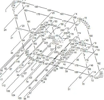
[image:6.612.110.504.452.578.2]Figure 4. CAD interface of auxiliary design software for wind farm grounding system.
Figure 5. Soil inversion module of wind farm grounding auxiliary design software.
[image:6.612.175.439.645.725.2]The grounding resistance of the wind farm is calculated to be 17.649083Ω by using the software. Using the same soil parameters, the model established by CDEGS is as follow:
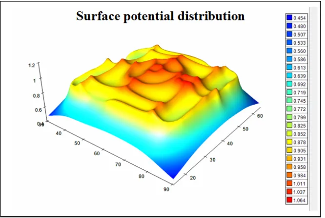
The grounding resistance of the wind farm is calculated to be 17.49931Ω by running CDEGS software.The results show that the earthing resistance of the software obtained in this paper is similar to that of CDEGS, indicating that the error is small and the results are reliable. But the software developed in this paper is more flexible and more connected with the actual situation. In addition, the visualization function of the wind farm grounding auxiliary design software is buried deep and powerful, and the schematic diagram is shown in Fig. 7.
Figure 7. Visualization function of grounding auxiliary design software for wind farm.
Conclusion
Grounding system is an important part of power transmission and transformation system, and it is the fundamental guarantee and important measures to maintain the safe and reliable operation of power system, and ensure the safety of operators and electrical equipment. Under normal operation, the grounding grid provides the working and reference ground potential for the weak equipment such as communication system, signal system and relay protection system, and provides protective grounding when the power supply fails or has surge. When the high voltage equipment in substation has a short grounding fault, the grounding system must provide a reliable return path for the fault current. Substation grounding device plays a vital role in ensuring the safe operation of power system. With the development of modern large power grid to ultrahigh pressure, high capacity and long distance, it is more and more demanding for the safety, stability and economic operation of power system. In order to ensure the safe and stable operation of power grid and improve the reliability of power supply, a safety protection system must be equipped with the primary system, so a good grounding device for the substation is needed.
The wind farm grounding design software developed in this paper has the advantages of friendly interface, simple operation and reliable operation. In the calculation, a variety of factors can be considered, the practica-bility is strong, and the calculation results are accurate.
References
[2] GB50065-2011, Grounding Design Specifications for AC Electrical Installations.
[3] Feng Lin, Lanying Zhang, Tingqin Lv, Yuewen Jiang, Analysis on Improvement Scheme of Grounding Resistance of Wind Farm Grounding Transformer and Its Neutral, Power Grid & Clean Energy, 2015, 31 (02): 126-130 + 134.
[4] Xiaobin Guo, Manhong Ye, Study on Grounding of Wind Farm in High Soil Resistivity Sandy Land, Electric Power Survey & Design, 2013, (05): 72-75 + 80.
[5] Mingyao Teng, Study on 35kV System Grounding of Wind Farm, Electronic World, 2013, (06): 63-64.
[6] Liang Chen, Yong Bai, Design of Grounding Eesistance Selection for Wind Farm, Electrical Manufacturing, 2013, (02): 54-57.
[7] Yang Liu, Analysis of mountainous wind farm grounding design scheme, Forestry Science and Technology Information, 2010, 42 (04): 50-52.
[8] Wei Shi, Qiuhong Wang, Wind farm grounding design, Electrical Manufacturing, 2010, (09): 48-49 + 66.
[9] Jingzeng Zhou, Grounding design of wind turbine in wind farm, Energy Engineering, 2010, (03): 41-43.