Systems Reference Library
IBM System/36D Component Description
IBM 2265 Display Station Modell
IBM 2845 Display Control
This manual describes the functional and operating characteristics of the
I
IBM 2265 Display Station Model 1 and the IBM 2845 Display Control. Thetwo units combine to form a display system that provides visual access to
I
data stored in an IBM System/360. The IBM 2265 Display Station Model 2, which can be attached only to an IBM 2772 Multi-Purpose Control Unit, is described in System Components: IBM 2770 Data Communications System, Form GA27-3013.
Preface
This SRL publication assumes the reader has a knowledge of System/360 principles of operation. Therefore, dis-cussions of such System/360 considerations as instruction and command structures, Channel Status Word and Pro-gram Status Word locations and usage, varieties and pri-orities of interruptions, and generalized capabilities such as I/O channel status and sense byte usage, command and data chaining, length suppression, etc., have been kept to a minimum. This publication does not differentiate be-tween the various models of System/360; i.e., main storage capacities, sub channel allocations, sharing and nonsharing of I/O channel and processor circuitry, and so forth. The reader is directed to the authoritative source for each model of System/360, System/360 Functional Character-istics (by model). Other IBM publications that will be of use to the reader are:
Third Edition (January, 1970)
I
IBM System/360 Principles of Operation, Form GA22-6821
IBM 2701 Data Adapter Unit - Component Description, Form GA22-6864
IBM System/360 Bibliography, Form GA22-6822 IBM Multiplexers and Communications Terminals
Installation Manual- Physical Planning, Form GA27-3006
Note: In this manual, "I/O (input/output) channel" refers to a multiplexer channel. This device provides the data path and controls between the central processor and the 2701 Data Adapter Unit. "Communications channel" refers to the communications medium (telephone lines, telegraph, microwave, etc.) used to transmit data, via appropriate data sets, between the 2701 and the 2265-1/ 2845 display system.
This is a major revision of, and obsoletes, Form A27-2731-1 and Technical Newsletter N27-2948. The significant changes in this edition include the following:
1. The title has been changed to reflect that this publication describes the 2265 Modell; a reference to the publication that describes the 2265 Model 2 has been added to the abstract. 2. Line Addressing Feature 4802 has been removed and Line Addressing Feature 4801 has
been revised.
3. Installation planning data has been replaced with a reference to the publication that contains this data.
4. Display station keyboard indicator and pushbutton names have been corrected.
Changes to text and tables are indicated by a vertical line to the left of the change; changed illustrations are denoted by the symbol. to the left of the caption.
Changes are periodically made to the specifications herein; before using this publication in connection with the operation of IBM systems, refer to the latest System/360 SRL Newsletter, Form GN20-0360, for the editions that are applicable.
Text for this manual has been prepared with the IBM SELECTRIC @Composer.
A form is provided at the back of this publication for reader's comments. If the form has been removed, comments may be addJ:essed to: IBM Systems Development Division, Product Publications, Dept. 520, Neighborhood Road, Bldg. 960-1, Kingston, N.Y., 12401.
Contents
Introduction 7 General Poll . 33
Highlights 7 Read Addressed Full DS Buffer 33
General Description 7 Write Addressed DS 36
Programming Support 8 Erase/Write Addressed DS . 37
Features . 8 Write Printer . 38
Specify Features 8 Printer Request Condition . 40
Data Set Adapters 8 Simultaneous Keyboard and Printer Operations 40
Display Format Features 9 Write DS Li~ Address . 41
World Trade Language Features 9 Summary of Sequences and Responses 42
Voltage Features 9 2845 Display Control Sequences and Responses 42
Special Features. 9 Start of Text (STX) 42
Alphameric Keyboard Feature (4766) 9 End of Text (ETX) . 42
1053 (Printer) Adapter Features 9 Cancel (CAi,O 42
Line Addressing Feature (4801) 9 Positive Acknowledgment (ACK) . 43
Destructive Cursor Feature (3301) 10 Negative Acknowledgment (NAK) 43
Tab Feature (7801) . 10 End of Transmission (EOT) 43
System Configuration 10 No Response 43
Data Sets. 10 I/O Channel Sequence and Responses 44
U.S. (Domestic) Operation 10 Start of Text (STX) 44
World Trade Operation. 10 End of Text (ETX) . 44
Typical Display System Operation 10 Positive Acknowledgment (ACK) 44
Operation with 1053 Printer 12 Negative Acknowledgment (NAK) 44
2265 Display Station Operator Controls and Indicators 12 Start of Heading (SOH) 44
Display Station Keyboard 13 End of Transmission (EOT) 44
Character Keys 13 Start of Text/End of Transmission (STX/EOT) 44
Control Keys 13 Line Feed (LF) 44
Special Symbols. 13 Error Recovery Procedures 45
Cursor-General Description 13 NAK Response to Addressing Sequence 45
Nondestructive Cursor Symbol (Standard) 13 NAK Response to Text 45
Destructive Cursor Symbol (Feature) 16 EOT Response to Addressing Sequence 45
End of Message (EOM) Symbol 16 EOT Response to Text . 45
Start of Message (SOM) Symbol 19 CAN Response 45
New Line (NL) Symbol 19 No Response to Addressing Sequence or Text 45 Check Symbol 19 I/O Channel Commands, CCW's, and Ending Status
Control Key Functions . 20 and Sense Bytes 46
2265 Display Station Keyboard Operations 20
Manual Input 20 Installation Planning Data 49
Use of New Line (NL) Symbol 22
Correction of Errors from 2265 Keyboard 22 Appendix A. Feature Charts 50
2265-to-Printer Operation . 22
Tab Feature Operation. 23
Display System Test Procedure (Wrap Test) . 23 Appendix B. World Trade Language Features 52
Introduction . 52
Principles of Operation 25 2265/2845 Character Sets . 52
USASCII Code Set 25 IBM 1053 Model 4 Printer Print Elements 53
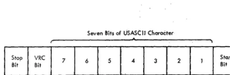
Transmission Code Byte Structure 25 2265/2845 Labels, Indicators, and Switches 53
Block Diagram Analysis 25
IBM 2701 Data Adapter Unit . 25 Appendix C. USASCII-8 to Hexadecimal
Data Sets. 25 Code Conversion 54
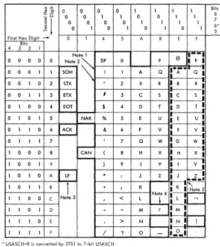
US ASCII Communication Control Characters 27 2845 Display Control Modes of Operation 27
Control Mode 27 Appendix D. Timing Considerations 55
Text Mode 27 Interface Timing 55
Parity Checking 28 27tH Line Timeout . 55
Addressing Sequence 28 Command Execution Timings . 55
2845 Commands and Command Operation 29
Specific Poll to 2265 Display Station 30 Index 57
Illustrations
Frontispiece IBM 2265 Display Station (Design Model) 8 General Poll, Sequence/Response Diagram 34 IBM 2845 Display Control (Design Model) 9 Read Addressed Full DS Buffer, Sequence/
1 Typical Connection of an IBM 2845 Display Response Diagram. 35
Control to a Remote Central Processor 10 Write Addressed DS, Sequence/Response
Showing Application in a Multidrop Com- Diagram 37
munications Network . 11 11 Erase/Write Addressed DS, Sequence/
2 2845 Display Station Keyboard 13 Response Diagram. 38
3 Example Display Showing SOM, NL, Check 12 Write Printer, Sequence/Response Diagram 39 Symbols, and Nondestructive Cursor (15 x 64 13 Write DS Line Address, Sequence/Response
Display Format) 21 Diagram 41
4 USASCII -8 Code Set 26 14 2265 Feature Chart . 50
5 Ten-Bit Format of Transmitted USASCII 15 2845 Feature Chart . 51
Characters 27 16 2265 United Kingdom Keyboard 52
6 Specific Poll to Display Station Sequence/ 17 2265 French Keyboard 52
Response Diagram. 31 18 2265 German Keyboard 53
7 Specific Poll to Printer, Sequence/Response 19 Command Execution Timings . 56
Diagram 32
Tables
1 Functions of 2265 Display Station Keys 8 I/O Channel Read Command Ending Status
(Nondestructive Cursor) 14 and Sense Bytes 48
2 Functions of 2265 Display Station Keys 9 2265/2845 and 1053 Language Feature
(Destructive Cursor) 17 Character Differences . 53
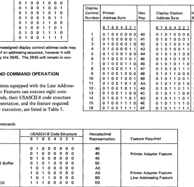
3 Display Control Address Assignments 29 10 United Kingdom, French, and German
4 Remote Device Address Assignments . 29 Labels, Indicators, and Switches . 53 5 2265/2845 Commands. 29 11 USASCII-8 to Hexadecimal Code
Con-6 Display Line Addresses . 42 version Chart 54
7 Sample CCW Formats for Information
IBM 2265 Display Station (Design Model)
The IBM 2845 Display Control, coupled with an IBM 12265 Display Station Modell, forms a display system that
provides rapid visual access (via communications facilities) to data stored in a remotely located System/360 Models 25
I
through 85 or 195. The 2265 Display Station Modell (hereafter called the 2265) is a high-speed display terminal that operates under control of the compact 2845 Display Control. The display system is designed to meet the requirements of customers whose facilities are widespread and who need a small number of display terminals at each facility capable of two-way communications with a centrally located computer.For example, consider a company whose central processing unit is located at company headquarters in
Chicago and whose branch offices and warehouses are scattered throughout the country. Each outlying loca-tion may be equipped with a number of 2265/2845 dis-play systems commensurate with its business volume. By means of communications facilities (such as phone lines, data channels, etc.), each display system can store data in, and receive visual information from, the central processor.
This system satisfies the needs of customers who re-quire relatively few displays or who desire to supplement an existing display system. It is ideally suited to applica-tions that require immediate data acquisition capabilities at relatively low cost.
An inquiry concerning an account, a transaction, a production schedule, etc., can be entered quickly and easily in the remote computer from the 2265 keyboard. After being processed by the computer, the desired information is displayed on the 2265 screen in the form of visual data. Here, the display information can be analyzed, modified if necessary, and, when desired, returned to the computer for further processing and storage.
The 2845 may also be equipped with a special feature to permit attachment of an IBM 1053 Model 4 Printer. The Printer may be used to produce a paper copy of data sent from the central processor or of data displayed on the 2265 screen.
HIGHLIGHTS
• Character presentation uses an advanced stroke-generation technique that results in characters of unusual clarity and smoothness.
• 2265 CRT uses Type P39 phosphor to produce a green-tinted display.
Introduction
• Each 2265 has a capacity of 960 characters, with an optional display format of either 15 rows of 64 charac-ters or 12 rows of 80 characcharac-ters.
• Transmission speeds of either 1200 bps or 2400 bps.
• Optional attachment of an IBM 1053 Model 4 Printer. • Optional attachment of an alphameric keyboard which
may be located up to 5 feet from the Display Station.
• Rapid cursor (character position marker) movement is provided in forward and backward directions.
• By operator control, the display screen can be erased either a line at a time, a section at a time, or completely.
• Optional Tab feature.
• A nondestructive cursor is standard; a destructive cursor is optional.
• Line addressing to permit selective writing is also available.
• For World Trade customers, a 50-Hz power option is available. Also available are keyboards for the following languages:
United Kingdom English French
German
GENERAL DESCRIPTION
The 2265/2845 display system consists of two separate 1 units: the IBM 2265 Display Station Modell and the IBM
2845 Display Control. The 2845 is a free-standing unit which contains the storage and control logic necessary to interface with a 2265 and appropria.te communications facilities. The unit provides for additional features such as the printer adapter and the 1200-bps or 2400-bps data set adapters described below.
The 2265 Display Station contains the 14-inch cathode-ray tube (CRT) upon whose screen a maximum of 960 alphameric characters can be displayed. The 2265 is equipped with an alphameric keyboard to make it a complete input/output (I/O) device. The keyboard is connected to the display station by a cable which permits the keyboard to be positioned up to 5 feet away from the display. Display station cover design is such that when the display and keyboard are correctly positioned together they appear as a single unit.
The face of the CRT (i.e., the display screen) is coated internally with Type P39 phosphor to produce characters having a green tint. By redrawing the displayed characters
I
approximately 50 times a second (technically, a refresh rate of approximately 50 Hz), a nonflickering image is formed. Through use of an advanced character-generation technique, the electron beam is moved in a series of short strokes to form each character. By deflecting the beam (up to a maximum of 40 times), blanking and unblanking it as necessary, a character is drawn on the display screen.The strokes required to compose each character are predefined and are automatically generated via digital-to-analog conversion by a character generator. Therefore, character generation need not be considered when pro-gramming the display system. The character generator responds to the characters received from the 2845 and produces the corresponding analog signals. These signals are applied to a deflection yoke surrounding the neck of the CRT to control the luminous trace of the electron beam. By blending together the strokes that compose each character, characters of unusual smoothness are formed on the display screen.
An antireflective display screen is used on the 2265 Dis-play Station to minimize reflections from ambient light sources and reflective objects. A manually operated bright-ness control ensures comfortable viewing in installations· 'with room light ambients of up to 75 footcandles.
PROGRAMMING SUPPORT
2701 Teleprocessing (TP) applications are made easier and more efficient by the use of the IBM-supplied programming-support packages. The primary programming-support packages consist of a pair of data-management access methods designed specifically for the TP environments. These access methods satisfy the programming requirements for a large portion of commonly used TP applications, including the 2848 and 2260. They operate under either a full Operating System (OS) or the smaller Disk Operation System (DOS). The 2265/2845 can operate under these two programming packages.
One of the access methods, BT AM (Basic Telecom-munication Access Method), provides the programmer with simple, efficient access to the communication environ· ment so that he can program the terminal in a manner 8
consistent with that used for conventional sequential-type I/O devices. BT AM controls data transmission; however, it does not provide for elaborate message-queuing capability or for actual processing of the message itself.
The second access method, QTAM (Queued Telecom-munication Access Method), provides all the above-mentioned capabilities of BT AM. In addition, it incor-porates facilities for queuing messages on direct-access storage devices (e.g., disk, drum, etc.). QTAM also pro-vides capabilities for data-collection and message-switching applications and may be used intact both for these functions and for a large range of other TP uses. Like BT AM, QT AM insulates the programmer from most of the programming details of the 2701 and the attached terminal equipment. The appropriate SRL publications should be consulted for detailed information concerning the use of these access methods.
In some cases, primarily because of special system con-figurations or requirements, TP programming can be more appropriately implemented if the user develops the I/O channel command programs for the 270 I /2845 operation. This publication provides programming information about the I/O channel commands used with the 2265/2845. These commands can be implemented through the EXCP (Execute Channel Program) macro instruction offered in each of the System/360 programming systems. This publication includes sufficient information for user pre-paration of the I/O channel program. Also, the user of the various programming-support packages will find this publication helpful.
FEATURES
Several features may be installed in the 2265/2845 display system. In certain cases, the feature is required to make the system function. These features must be specified by the customer and are, therefore, referred to as Specify features. An example of a Specify feature is the Display Fonnat Feature. Other features are optional and, when installed, expand the capabilities of the system. These are referred to as special features. An example of a special feature is the Printer Adapter Feature. Although this special feature is not essential to the display system oper-ation, it does expand the system's capability to include control of an output printer. Both types of features are described more fully below. All features are summarized in Figures 14 and 15 of Appendix A.
Specify Features
One each of the following features must be installed in the 2845 Display Control. (The number appearing in parentheses after the feature name is the feature number.) Data Set Adapters
with the System/360 channel by means of appropriate data sets and channels via an IBM 2701 Data Adapter Unit. These control functions include synchronization and recognition of special communications-channel-line-control characters, decoding and temporary storage of commands, and transfer of data and control information between the 2845 display buffer and the attached data set. To interface with the appropriate data set (see "Data Sets"), one of the following data set adapters must be specified: I
Data Set Adapter (9012). This adapter permits attachment of the 2845 to a data set operating at a,speed of 1200 bps; it also provides the necessary clocking.
Data Set Adapter (9013). This/adapter permits attachment of the 2845 to a data set operating at a speed of 2400 bps. Clocking must be provided by the data set.
Display Format Features
The characters displayed on the Display Station screen may be presented in one of two display image formats. One format displays 15 lines of 64 characters each; the second format displays 12 lines of 80 characters each. With either format, the total number of characters that may be dis-played is 960. One of the features described in the follow-ing two paragraphs must be chosen to display the desired format.
Display Format (9101). This display format uses a large character with a horizontal character step of 0.16 inch and a vertical line step of 0.32 inch to display 15 rows of 64 characters .. The resulting display frame measures nominally 10.3 inches by 4.6 inches.
Display Format (9102). This display format uses a some-what smaller character than the 9101, with a horizontal character step of 0.13 inch and a vertical character step of 0.26 inch to display 12 rows of 80 characters. The resulting display frame measures nominally 10.3 inches by 3.0 inches.
World Trade Language Features
World Trade models must have one of the World Trade Language Features installed. The language feature provides the 2265 and 2845 with equipment labels and a character generator appropriate to the language specified. See Appendix A for feature numbers and Appendix B for World Trade label, indicator and switch translations, and unique character codes.
Voltage Features
A voltage feature must be specified for U.S. (Domestic) and World Trade models of the 2265 and 2845. These features are summarized (with feature numbers) in Figures 14 and 15 of Appendix A.
Special Features
The following special features may be selected at the option of the customer. (The number in parentheses following the feature name is the feature number.)
Alphameric Keyboard Feature (4766)
This feature permits the operator to key in data at the Display Station for display and/or transmission to the central computer. When a 1053 Printer is attached to the 2845, the keyboard also permits a paper copy of the dis-played data to be printed.
As World Trade options, keyboards are available in four languages. When a keyboard is selected, it is pro-vided in the same language as specified under the World Trade Language feature. (See Figures 16, 17, and 18 in Appendix B for layout of keyboards.)
1053 (Printer) Adapter Features
A 1053 adapter feature controls the printing of informa-tion by the IBM 1053 Printer. The informainforma-tion to be printed may originate at the central processor and be addressed specifically to the Printer, or the information may be that which is currently being displayed on a 2265 Display Station screen. In the latter case, the 1053 Adapter Feature controls the transfer of displayed data to the Printer to obtain a permanent record of the data. The following two adapter features are mutually exclusive, and their sele.ction depends upon which Display Format Feature is installed.
1053 Adapter Feature (7927). This feature permits attachment of an IBM 1053 Printer to a 2845 Display Control equipped with Display Format Feature 9101. It allows printing of messages of up to 240 characters from the computer. It also allows printing of messages displayed on a 2265 screen in the 15-rows-of-64-characters format.
1053 Adapter Feature (7928). This feature permits the attachment of an IBM 1053 Printer to a 2845 Display Con-trol equipped with Display Format Feature 9102. It
allows printing of messages of up to 240 characters from the computer. It also allows printing of messages displayed on a 2265 screen in the 12-rows-of-80-characters format. Note: The 1053 Printer supplied for World Trade use with the 2845 must have the appropriate World Trade language feature. The print ball supplied contains characters unique to the language specified.
I
Line Addressing Feature (4801)The line addressing feature permits the program to select the location on the 2265 screen at which a display message will start. The display starting locations coincide with the first character position of each row (line) of the 2265
screen. The line address is included as part of the message transmitted under the Write Line Address command and is described under "Principles of Operation".
Destructive Cursor Feature (3301)
When this feature is installed in the 2845, the destructive cursor symbol replaces the standard nondestructive cursor symbol as the display position marker. The destructive cursor symbol appears on the 2265 screen as a horizontal bar ( _). The cursor marks the display position that the next character will occupy. From the 2265 keyboard, the cursor may be backspaced or advanced one space at a time, moved up or- down, or moved to the beginning of the next line. Any character occupying the position to which the destructive cursor is moved is deleted. (Further infor-mation concerning both the destructive and nondestructive cursors is found under "Special Symbols.")
Tab Feature (7801)
This special feature permits keyboard indexing of the cursor. Depressing the TAB key initiates a search for a colon. Upon detection of a colon, the cursor "is reposi-tioned to the character position immediately following the colon. When the nondestructive cursor is used, there is no change in the display other than the repositioning of the cursor. When the Destructive Cursor Feature is installed any character located in the position immediately
follO\~ing
the colon is replaced by the destructive cursor. This .replacement and the repositioning of the cursor are the only changes in the display.New Line (NL) characters have no effect on the tab operation. Character locations to the right of an NL character are also searched for the presence of a colon.
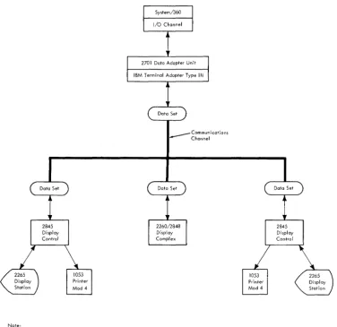
SYSTEM CONFIGURATION
Figure 1 is a block diagram of a possible 2265/2845 con-figuration. A basic system is the same except that the 1053 block would be absent. The 2265/2845 display system is program-compatible with the IBM 2848 Display Control, Models 1, 2, and 3, equpped with the Data Set Adapter. The{efore, the 2848 as well as the 2845 may be attached to the same communications channel in a multidrop (multistation) configuration.
10
DATA SETS
One of the data sets described in the following paragraphs is required to interface the 2845 Display Control with the communications channel.
U.S. (Domestic) Operation
In U.S. (Domestic) operation, the 2845 Display Control operates at 1200 or 2400 bps, point to point and multi-point.
For 1200-bps operation, four-wire Telephone Company or Western Union Type 3002 four-wire duplex facilities with C 1 Conditioning* is required. Western Electric Data Set 202D I * is specified. Clocking is provided by the 2845.
For 2400-bps operation, four-wire Telephone Company or Western Union Type 3002 four-wire duplex facilities with C2 Conditioning* is required. Western Electric Data Set 201 B 1 * is specified. Clocking is provided by the data set.
World Trade Operation
Operation with the following data sets (modems) in a point-to-point or multipoint configuration over four-wire service is at 1200 bps only:
IBM 3976 Modem Model 3
I
IBM 3977 Modem Model 2.Like modems must be used in a given configuration.
TYPICAL DISPLAY SYSTEM OPERATION
The 2265/2845 display system provides a rapid and efficient means of two-way communication with the remotely located central processor. The extent and flexibility of data manipulation is a function of the Specify and special features installed in a given display system. Following is a brief description of a typical display system
operation. '
Assume, initially, that the Display Station screen is blank except for a Start of Message symbol ( ~) in the first character position and a character position marker (-), called a cursor, in the second character position in the upper left corner of the display screen. The operator simply keys in a message on the typewriter-like keyboard. As each key is depressed, the corresponding character is stored in a buffer in the 2845 and simultaneously dis-played on the 2265 screen. As each character is keyed in, the cursor advances one display position. The cursor thus serves as a marker to indicate the display position the next character will occupy on the screen. When the message is
Note:
A maximum of sixteen 2845's may be multi-dropped on one communications channel.
_ _ _ Communications Channel
Figure 1. Typical Connection of an IBM 2845 Display Control to a Remote Central Processor Showing Application in a Multidrop Communications Network.
complete, the operator visually verifies the message and then depresses the ENTER key. At the same time, the Ikeyboard locks and the ENTER PENDING indicator on the
keyboard lights. The next time the Display Station is polled by the central processor, the completed message is
auto-I
matically transmitted to the processor. The ENTER PENDING indicator remains lit until the polling operation has been successfully terminated. When the indicator turns off, the Start of Message (SOM) symbol disappears, the keyboard unlocks, and the operator is free to key in another message.Under program control at the central processor, messages may also be sent from the central processor to the 2845 and displayed on the Display Station screen. Characters of the message text are displayed on the screen, beginning at the character position currently occupied by the cursor.
If the Display Control is equipped with the Line Addressing feature, the program may designate that the first character be displayed in the first character position of a specified line. By the use of various commands, the program may erase all data from the Display Station screen or may caUse· all data stored in the display buffer to be transmitted to the central processor.
Tlie screen may also be erased by the Display Station operator. In addition to being able to erase the complete screen, the operator may selectively erase all data from the cursor to the end of that line or from the cursor to the end of the screen. The operator may erase any character or replace it with another simply by positioning the cursor to the described character location and depressing the
[image:11.617.81.457.70.435.2]· depressing a different character key (to replace the charac-ter). Rapid positioning of the cursor by the operator is also provided. By depressing the proper key, the cursor may be moved up, down, left, or right.
The functions of the commands and keyboard keys are described in detail later in this publication.
OPERATION WITH 1053 PRINTER
When a 1053 Printer is attached to the Display Control, the data displayed on a 2265 screen can be printed by depressing the PRINT key on the 2265 keyboard. All data from the first displayable character position of the screen up to the character position occupied by the cursor (except for those characters to the right of and on the same line as the NL character) are transferred to the Printer. Detection of the EOM symbol ends the print operation immediately after the EOM symbol is printed. Because the EOM symbol may be displayed to the right of an NL symbol, all charac-ter positions to the right of an NL symbol are searched for an EOM symbol even through the characters displayed in these positions are not printed. (The EOM symbol itself is printed.)
If an internal parity error occurs within the 2845 after a keyboard print operation is initiated and before the operation is terminated, a Check symbol ( ' ) is printed as the last character of the printed text. The Check symbol notifies the operator that an internal parity error has been detected, but does not identify the character(s) involved. The parity error may have occurred in either the display buffer or the printer buffer. In any case, all characters are printed as they exist in the display buffer.
Remotely, by means of a Write Printer command, the central processor may send a message of up to 240 characters via the 2845 to the 1053 Model 4 Printer. The entire message is received and stored in the printer buffer of the 2845 before it is transferred to the Printer. If an error is detected during message transmission, transfer to the Printer is inhibited and the entire message must be retransmitted. If, however, no errors are detected in transmission, receipt of the final message character initiates transfer of the message to the Printer and printing com-mences.
As in the keyboard PRINT key operation, detection of an internal parity error, either in the printer buffer or display buffer of the 2848, causes a Check symbol to be printed as the last character of the printed message. The Check character simply indicates that an error has been detected within the 2845 but does not identify the character( s) involved.
A message of up to 240 characters may be sent by -the central processor to the Printer via the 2845. A Printer message of greater length may be sent to the Display Station, with the operator instructed (as part of the message) to execute a keyboard Print operation. Or, th~
12
message may be sent in individual Write Printer trans-missions of 240 characters or less directly to the Printer. During transmission from the central processor to the Printer, data displayed on the display screen is not affected.
The 1053 Piinter, when controlled by the 2845, is equipped with a special print element that permits printing of the SOM, EOM, and Check symbols. Therefore, all characters are printed as they exist in the printer buffer. However, the NL symbol is not printed; rather, it causes a carriage return/line feed (CR/LF) operation.
2265 DISPLAY STATION OPERATOR CON'FROLS AND INDICATORS
Operator controls on the 2265 Display Station (not including those located on the keyboard) are a POWER ON switch/indicator, a POWER OFF switch, and a Brightness control. (A single POWER ON/OFF switch is the only control on the 2845 Display Control accessible to the operator.)
The POWER ON switch/indicator is located on the front right side of the 2265. Upon depression of this switch/ indicator, all voltages required for operation are supplied to the 2265 and 2845 provided the 2845 POWER ON/OFF switch is set to ON. When all power is on in both units, the 2265 POWER ON switch/indicator lights. Voltages necessary for operation are turned off in both units when either the 2265 POWER OFF switch (located immediately below the POWER ON switch/indicator) is depressed or when the 2845 POWER ON/OFF switch is flipped to OFF. (A 49V source, located in the 2845, is energized and
supplies 49V to the 2265 when the 2845 POWER ON/OFF switch is ON regardless of the condition of the 2265. power switches. However, other voltages, off at this time, are required to make both units operational.)
The Brightness control is located immediately above the POWER ON switch/indicator on the 2265. Rotating the Brightness control knob clockwise increases the brightness of the characters displayed on the screen, thus enabling the operator to adjust the brightness to a com-fortable viewing level.
Two indicators are located on the 2265 keyboard. The DATA SET READY indicator notifies the Display Station operator that the attached data sethas power on and is
I
ready to function. The ENTER PENDING indicator informs the operator that an Enter operation is pending.I
While the ENTER PENDING indicator is lit, the keyboard is locked. The ENTER PENDING indicator lights when the ENTER key is depressed and is extinguished when one of the following occurs:1. Polling of the Display Station is successfully terminated. 2. The RESET key is depressed before 2845 recognition
of a specific or general poll.
A TEST key enables the operator to quickly test the display system. By observing the display screen, a judgment may be made as to the operational status of the 2265 and 2845. The test procedure is described fully under "Display System Test Procedure".
DISPLAY STATION KEYBOARD
Images to be displayed on the 2265 Display Station screen may be initiated at the Display Station keyboard (Figure 2). Through use of the keyboard data character and control keys, the operator may compose the text to be displayed and may communicate with the 2845 regarding disposition of the text.
. Character Keys
The characters that may be displayed consist of 26 uppercase alphabetic characters, 10 numeric characters, and 23 punctuation (or special) characters. Operation of any of the character keys causes the selected character to be displayed on the screen in the character position occupied by the cursor.
Control Keys
See Tables 1 and 2 for a listing of the 2265 control keys and their functions. Note that rapid cursor positioning can Ibe performed by the SPACE/ERASE-ADVANCE and
BKSP (Backspace) keys. That is, when any of these keys are depressed to their final stop, the operation of the key is continuously repeated at about nine characters per second as long as the key is held depressed (unless inter-rupted by an I/O operation).
OJ
ITJ
OJ
IT] IT] [I]
[] IT]
Special Symbols
The special symbols described in the following paragraphs can be displayed on the screen of the 2265.
Cursor - General Description
The cursor is an automatically inserted visual display position marker; it denotes the display position on the 2265 screen that the next character entered will occupy. Two types of cursor symbols, nondestructive and destruc-tive, are available to permit selection of the cursor best suited to individual applications. Both are described below.
Nondestructive Cursor Symbol (Standard)
The nondestructive cursor symbol appears as _. It indicates the character position to be occupied by the next character entered on the display. The nondestructive cursor symbol appears on the 2265 screen below the character line and immediately below the character position the next character entered will occupy. Since the nondestructive cursor symbol occupies a display area below the character line, it may be moved about freely on the 2265 screen without interfering with other characters. Table 1 explains the effect that each 2265 keyboard key has on the nondestruc-tive cursor symbol.
The movement of the nondestructive cursor symbol and its position relative to other display characters during the time the data is entered from the 2265 keyboard are described under "Control Key Functions." Also, see Programming Note under "Destructive Cursor Symbol (Feature)".
ENTER DATA SET PENDING READY
©
©
OJ
OJ
0
B
~
[8J
~GJIGJIGJIQIQI[JlmIUJIOJIQ,I~ ~
TAO
[JDGJDGJGJ[JGJCJ[J;&]~
c::J
GJ
[J
GJ
GJ
[J
GJ GJ
[J
D
[IJ
~
I
I
SPACE/ERASEA15vANCE
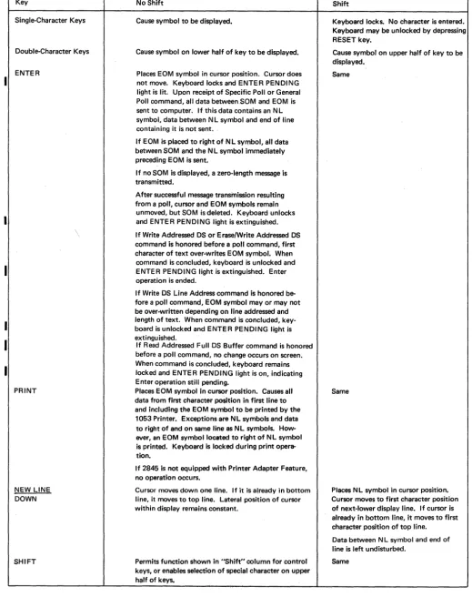
Table 1. Functions of 2265 Display Station Keys (Nondestructive Cursor)
Key No Shift Shift
Single-Character Keys Cause symbol to be displayed. Keyboard locks. No character is entered. Keyboard may be unlocked by depressing RESET key.
Double-Character Keys Cause symbol on lower half of key to be displayed. Cause symbol on upper half of key to be displayed.
ENTER Places EOM symbol in cursor position. Cursor does Same not move. Keyboard locks and ENTER PENDING
light is lit. Upon receipt of Specific Poll or General Poll command, all data between.SOM and EOM is sent to computer. If this data contains an N L symbol, data between N L symbol and end of line containing it is not sent.
If EOM is placed to right of NL symbol, all data between SOM and the N L symbol immediately preceding EOM is sent.
If no SOM is displayed, a zero-length message is transmitted.
After successful message transmission resulting from a poll, cursor and EOM symbols remain
unmoved, but SOM is deleted. Keyboard unlocks and ENTER PENDING light is extinguished. \ If Write Addressed DS or Erase/Write Addressed DS
command is honored before a poll command, first character of text over-writes EOM symbol. When
command is concluded, keyboard is unlocked and ENTER PENDING light is extinguished. Enter operation is ended.
If Write DS Line Address command is honored be-fore a poll command, EOM symbol mayor may not be over-written depending on line addressed and length of text. When command is concluded, key-board is unlocked and ENTER PENDING light is extinguished.
If Read Addressed Full DS Buffer command is honored before a poll command, no change occurs on screen.
I
When command is concluded, keyboard remains locked and ENTER PENDING light is on, indicating Enter operation still pending.PRINT Places EOM symbol in cursor position. Causes all Same data from first character poSition in first line to
and including the EOM symbol to be printed by the 1053 Printer. Exceptions are NL symbols and data to right of and on same line as NL symbols. How-ever, an eOM symbol located to right of NL symbol is printed. Keyboard is locked during print opera-tion.
If 2845 is not equipped with Printer Adapter Feature, no operation occurs.
NEW LINE Cursor moves down one line. If it is already in bottom Places N L symbol in cursor position. DOWN line, it moves to top line. Lateral position of cursor Cursor moves to first character position
within display remains constant. of next-lower display line. If cursor is already in bottom line, it moves to first character position of top line.
Data between NL symbol and end of line is left undisturbed.
SHIFT Permits function shown in "Shift" column for control Same keys, or enables selection of special character on upper
[image:14.618.27.546.91.747.2]I
I
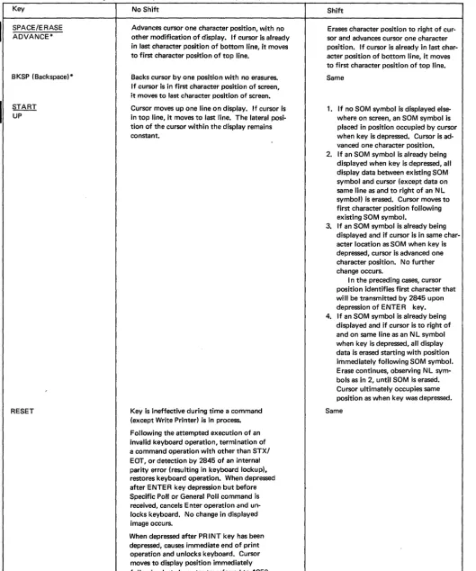
Table 1. Functions of 2265 Display Station Keys (Nondestructive Cursor) (Cont)
Key No Shift Shift
SPACE/ERASE Advances cursor one character position, with no Erases character position to right of cur-ADVANCE* other modification of display. If cursor is already sor and advances cursor one character
in last character position of bottom line, it moves position. If cursor is already in last char-to first character position of char-top line. acter position of bottom line, it moves
to first character position of top line. BKSP (Backspace)* Backs cursor by one position with no erasures. Same
If cursor is in first character position of screen, it moves to last character position of screen.
START Cursor moves up one line on display. If cursor is 1. If no SOM symbol is displayed else-UP in top line, it moves to last line. The lateral posi- where on screen, an SOM symbol is
tion of the cursor within the display remains placed in position occupied by cursor
constant. when key is depressed. Cursor is
ad-vanced one character position. 2. If an SOM symbol is already being
displayed when key is depressed, all display data between existing SOM symbol and cursor (except data on same line as and to right of an NL symbol) is erased. Cursor moves to first character position following existing SOM symbol.
3. If an SOM symbol is already being displayed and if cursor is in same char-acter location as SOM when key is depressed, cursor is advanced one character position. No further change occurs.
I n the preceding cases, cursor position identifies first character that will be transmitted by 2845 upon depression of ENTER key. 4. If an SOM symbol is already being
displayed and if cursor is to right of and on same line as an N L symbol when key is depressed, all display data is erased starting with position immediately following SOM symbol. Erase continues, observing NL sym-bols as in 2, until SOM is erased. Cursor ultimately occupies same position as when key was depressed.
RESET Key is ineffective during time a command Same (except Write Printer) is in process.
Following the attempted execution of an invalid keyboard operation, termination of a command operation with other than STX/ EOT, or detection by 2845 of an internal parity error (resulting in keyboard lockup), restores keyboard operation. When depressed after ENTER key depression but before Specific Poll or General Poll command is received, cancels Enter operation and un-locks keyboard. No change in displayed image occurs.
When depressed after PRINT key has been depressed, causes immediate end of print operation and unlocks keyboard. Cursor moves to display position immediately following last character transferred to 1053 Printer.
[image:15.621.73.602.70.704.2]I
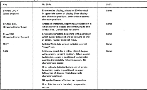
Table 1. Functions of 2265 Display Station Keys (Nondestructive Cursor) (Cont)
Key No Shift Shift
ERASE DPLY Erases entire display, places an SOM symbol Same (Erase Display) in upper left corner of display (first
display-able character position), and cursor in second character position.
ERASE E0L Erases all characters, beginning with position in Same (Erase to End of Line) which cursor is located and continuing to end
of that line. Cursor does not move. ,
Erase EOS Erases all characters, beginning with position in Same (Erase to End of Screen) which cursor is located and continuing to end
of screen. Cursor does not move.
TEST Isolates 2845 data set and initiates internal Same "wrap" test.
TAB Initiates a search for a colon. Search begins Same with cursor's present position. When a colon
is detected, cursor is positioned to character position immediately following colon. No characters are erased.
If no colon is detected before end of screen is reached, cursor is positioned to upper left corner of display (first displayable character position).
NL symbol has no effect on tab operation.
If no Tab feature is installed, no operation occurs.
Destructive Cursor Symbol (Feature)
The destructive cursor symbol appears on the screen of the 2265 as a heavy horizontal bar (-); it marks the display position that the next character entered will occupy. Table 2 explains the effect of each keyboard key on the destructive cursor symbol. When the destructive cursor is advanced, backspaced, or otherwise moved to a character position containing a character, the character is erased.
The movement of the destructive cursor symbol and its position relative to other display characters during the time data is entered from the 2265 keyboard are described under "Control Key Functions".
PROGRAMMING NOTE: Whether the nondestructive cursor symbol or the destructive cursor symbol is being used as a 2265 display position marker, the EOM symbol will appear on the 2265 screen in the position occupied by the cursor when the keyboard ENTER key is depressed (as in manual input operations) or when the PRINT key is depressed.
To ensure correct manual input operations when the nondestructive cursor is used, the EOM symbol should be deleted from the 2265 screen between message transfers. This can be accomplished through programming (by issuing an Erase/Write following a Poll command) or by the operator at the keyboard (by overwriting the EOM symbol). End of Message (EOM) Symbol
Whether or not the 2845 is equipped with the Destructive Cursor Feature, the EOM symbol (_) designates the end of a message. In appearance it is identical with the
destructive cursor symbol. The EOM symbol is displayed by depressing the ENTER key or the PRINT key or by transmitting -the EOM code from the I/O channel to the 2265. The latter course should be avoided since the presence of both an EOM symbol and a destructive cursor symbol can be confusing to a viewer and can cause an operation to be prematurely terminated. However, when a message is transmitted from the I/O channel to the 1053 Printer, the EOM code should be transmitted as the last character to denote the end of the message. The EOM code is printed by the 1053 Printer as an EOM symbol and it also causes a 1053 carriage return/line feed function.
The differences between an EOM symbol and the destructive cursor symbol are:
1. The cursor denotes the display position that the next character entered will occupy. The EOM symbol denotes only the end of a message.
2. The cursor advances as data is entered and can be moved about the 2265 screen. The EOM symbol, when dis-played, remains stationary.
3. The cursor is automatically inserted and is displayed at all times. The EOM is displayed only when the ENTER or PRINT key is depressed or when its code is transmitted from the I/O channel to the 2265. 4. Only one cursor symbol may be validly displayed on
a 2265 screen, whereas it is possible to display multiple EOM symbols.
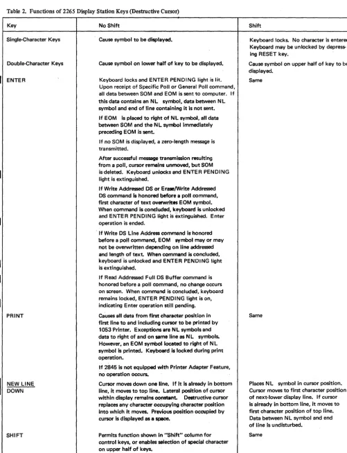
[image:16.623.37.539.65.370.2]Table 2. Functions of 2265 Display Station Keys (Destructive Cursor)
Key
Single-Character Keys
Double-Character Keys
ENTER
I
NEW LINE DOWNSHIFT
No Shift
Cause symbol to be displayed.
Cause symbol on lower half of key to be displayed.
Keyboard locks and ENTER PENDING light is lit. Upon receipt of Specific Poll or General Poll command, all data between SOM and EOM is sent to computer. If this data contains an NL symbol, data between NL symbol and end of line containing it is not sent.
If EOM is placed to right of NL symbol, all data between SOM and the N L symbol immediately preceding EOM is sent.
If no SOM is displayed, a zero-length message is transmitted.
After successful message transmission resulting from a poll, cursor remains unmoved, but SOM is deleted. Keyboard unlocks and ENTER PENDING light is extinguished.
If Write Addressed OS or Erase/Write Addressed OS command is honored before a poll command, first character of text overwrites EOM symbol. When command is coneluded, keyboard is unlocked and ENTER PENDING lightis extinguished. Enter operation is ended.
If Write OS Line Address command is honored before a poll command, EOM symbol mayor may not be overwritten depending on line addressed and length of text. When command is concluded, keyboard-is unlocked and ENTER PENDING light is extinguished.
If Read Addressed Full DS Buffer command is honored before a poll command, no change occurs on screen. When command is concluded, keyboard remains locked, ENTER PENDING light is on, indicating Enter operation still pending.
Causes all data from first character position in first line to and including cursor to be printed by 1053 Printer. Exceptions.re NL symbols and data to right of and on same Une as NL symbols. However, an EOM symbol located to right of NL symbol is printed. Keyboard is locked during print operation.
If 2845 is not equipped with Printer Adapter Feature, no operation occurs. .
Cursor moves down one line. If it is already in bottom line, it moves to top line. Lateral position of cursor within display remains oonetant. Destructive cursor replaces any character occupying character position into which it moves. Previous position occupied by cursor is displayed as a ~.
Permits function shown in "Shift" column for control keys, or enables selection of special character on upper half of keys.
Shift
Keyboard locks. No character is entered. Keyboard may be unlocked by depress-ing RESET key.
Cause symbol on upper half of key to be displayed.
Same
Same
Places N L symbol in cursor position. Cursor moves to first character position of next-lower display line. If cursor is already in bottom line, it moves to first character position of top line. Data between N L symbol and end of line is undisturbed.
Same
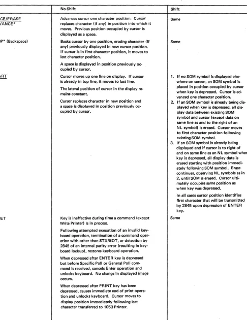
[image:17.621.66.568.59.714.2]Table 2. Functions of 2265 Display Station Keys (Destructive Cursor) (Cont)
Key No Shift Shift
SPACE/ERASE Advances cursor one character position. Cursor Same ADVANCE* replaces character (if any) in position into which it
moves. Previous position occupied by cursor is displayed as a space.
BKSP* (Backspace) Backs cursor by one position, erasing character (if Same any) previously displayed in new cursor position.
If cursor is in first character position, it moves to last character position.
A space is displayed in position previously oc-cupied by cursor.
START Cursor moves up one line on display. If cursor 1. If no SOM symbol is displayed
else-~ is already in top line, it moves to last line. where on screen, an SOM symbol is The lateral position of cursor in the display re- placed in position occupied by cursor mains constant. when key is depressed. Cursor is
ad-vanced one character position. Cursor replaces character in new position and 2. If an SOM symbol is already being dis-a spdis-ace is displdis-ayed in position previously oc- played when key is depressed, all
dis-cupied by cursor. play data between existing SOM
symbol and cursor (except data on same line as and to the right of an N L symbol) is erased. Cursor moves to first character position following existing SOM symbol.
3. If an SOM symbol is already being displayed and if cursor is to right of and on same line as an N L symbol when key is depressed, all display data is erased starting with position immedi-ately following SOM symbol. Erase continues, observing NL symbols as in 2, until SOM is erased. Cursor ulti-mately occupies same position as when key was depressed.
I n all cases cursor position identifies first character that will be transmitted by 2845 upon depression of ENTER key.
RESET Key is ineffective during time a command (except Same Write Printer) is in process.
Following attempted execution of an invalid key-board operation, termination of a command oper-ation with other than STX/EOT, or detection by 2845 of an internal parity error (resulting in key-board lockup), restores keykey-board operation.
When depressed after ENTE R key is depressed but before Specific Poll or General Poll com-mand is received, cancels Enter operation and unlocks keyboard. No change in displayed image occurs.
When depressed after PRINT key has been depressed, causes immediate end of print opera-tion and unlocks keyboard. Cursor moves to display position immediately following last character transferred to 1053 Printer.
*Rapid cursor positioning may be performed with this key. That is, if depressed to its final stop, the key's operation is repeated at about nine characters per second as long as the key is held depressed.
[image:18.620.66.553.80.710.2]I
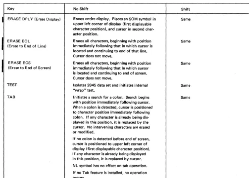
Table 2. Functions of 2265 Display Station Keys (Destructive Cursor) (Cont)
Key No Shift Shift
ERASE DPl Y (Erase Display) Erases entire display. Places an SOM symbol in Same upper left corner of display (first displayable
character position), and cursor in second char-acter position.
ERASE EOl Erases all characters, beginning with position Same (Erase to End of Line) immediately following that in which cursor is
located and continuing to end of that line. Cursor does not move.
ERASE EOS Erases all characters, beginning with position Same (Erase to End of Screen) immediately following that in which cursor
is located and continuing to end of screen. Cursor does not move.
TEST Isolates 2845 data set and initiates internal Same "wrap" test.
TAB Initiates a search for a colon. Search begins Same with position immediately following cursor.
When a colon is detected, cursor is positioned to character position immediately following colon. If any character is already being dis-played in this position, it is replaced by the cursor. No intervening characters are erased or modified.
If no colon is detected before end of screen, cursor is positioned to upper left corner of display (first displayable character position). I f any character is already being displayed . in this position, it is replaced by cursor.
Nl symbol has no effect on tab operation.
If no Tab feature is installed, no operation occurs.
New Line (N L) Symbol Start of Message (SOM) Symbol
The SOM symbol ( ~) is used to indicate the beginning
The NL symbol (~ ), when displayed on the 2265 screen, prohibits the transfer of all data displayed between the of data that is to be transferred from a display buffer to
the I/O channel during a Specific Poll or General Poll operation. If data is to be transferred during one of these operations, the SOM symbol must be displayed on the 2265 screen before the data to be transferred. Upon successful completion of either operation, the SOM symbol is automatically deleted from the 2265 screen. Deletion of this symbol signifies to the 2265 operator that the data has been successfully transferred from the display buffer and that another message may be entered.
The SOM symbol is made to appear on a 2265 screen by depressing the START key on the keyboard of the 2265 or by transmitting the code configuration of the symbol from the I/O channel to the 2265. For additional information concerning the SOM symbol, refer to the description of the above operations under "Principles of Operation" and "2265 Display Station Keyboard Oper-ations."
NL symbol and the end of the display line containing the symbol during a Specific Poll or General Poll operation. The NL symbol may be either keyboard- or program-inserted; it enables transfer of only a portion or portions of data displayed on the 2265 screen during either of the above operations. The effect of depressing the NEW LINE key is described in Tables 1 and 2.
Check Symbol
[image:19.623.66.570.93.454.2]A single parity bit is assigned to two characters in the 2845 buffer storage. As a result, if a buffer parity error is detected within the 2845, two Check symbols are dis-played on the 2265 screen since' either character. may be in error. See Figure 3. Due to the storage method used, these Check symbols appear exactly eight lines apart in the 15 x 64 display format (6 lines apart in the 12 x 80 display format) and in the character positions immedi-ately following the characters in which the parity error occurred. If either of the display positions following the possible characters in,error contains a character, the Check character will replace that character. If the 15 x 64 display format is used, a parity error occurring in the eighth display line will display one Check character on that line only. A second Check character is not displayed elsewhere on the screen since no 16th line is displayed.
Upon display of the Check characters, the keyboard is, in effect, locked. That is, the next attempted keyboard entry locks the keyboard, and the character is not entered into the display buffer nor displayed. Thus the operator receives a positive indication that an error has been detected. Following operator verification of the cause of the locked keyboard, the keyboard maybe restored (unlocked), and keyboard entry resumed, by depressing the RESET key.
IPROGRAMMING NOTE: If a Read Addressed Full DS Buffer command is begun before the keyboard has been stored (RESET key depressed), a CAN character is automatically transmitted following the display buffer contents. No CAN character is trans-mitted if the RESET key is depressed before the read buffer oper-ation is started. When an internal parity error is detected by the 2845 in any character stored in the display buffer, the error is identified by display of the check character. If an internal parity . error is detected after the ENTER key is depressed and the Display Station is polled, the CAN character is transmitted following the last character of text. CAN is transmitted even though the parity error did not occur in one of the characters of the Display Station message. The operator may intervene at any time after the ENTER key is depressed but before a poll command is recognized by the 2848 if a check character is noted on the display screen. By depressing the RESET key, the operator interrupts the Enter operation. If the character in error is not included in the Display Station message (error affects other data displayed on the screen), the ENTER key is again depressed. These actions prevent the CAN character from being transmitted in the message. However, if the check character appears in the Display Station message, the operator may correct the error by inserting the proper character and again depressing the ENTER key.
CONTROL KEY FUNCTIONS
The actions that occur when certain control keys are depressed are described in Tables 1 and 2 for both the nondestructive and destructive cursor. The display symbols associated with control key functions, where applicable, are as follows: .
1. SaM symbol ~
2. NL symbol ~
3. Nondestructive cursor _ : This symbol is displayed immediately below the next displayable position, thus ABC _ . If the D character key is depressed, the new display will appear as ABCD _ .
4. Destructive cursor -: The small horizontal bar is the destructive cursor symbol and denotes the next available display position, thus ABC - . If the D character key is depressed, the display will appear as
ABCD-The control keys, described in Tables 1 and 2, all appear on 2265 Display Station keyboards even when the feature associated with the key is not installed in the associated 2845 Display Control. For example, the PRINT key is present on the 2265 keyboard even though the attached 2845 is not equipped with the Printer Adapter feature. The data in Tables 1 and 2 for each control key includes a description of the effect of depressing the key when the associated feature is not present.
2265 DISPLAY STATION KEYBOARD OPERATIONS
Manual Input
The following describes the procedures for manually entering data into the display buffer (from the keyboard) for transfer to the I/O channel during a Specific Poll or General Poll operation:
1. Position the cursor in the character position where the message is to begin. Refer to Tables I and 2 to select a keyboard keyes) that will facilitate positioning the cursor.
2. Depress the SHIFT key and simultaneously depress the START key. This causes the SaM symbol to be entered in the display buffer and to appear on the 2265 screen in the character position previously occupied by the cursor. The cursor is advanced to the next display position.
3. Key in the message to be transferred to the I/O channel. The message data will appear on the 2265 screen as the character keys are operated. The cursor symbol auto-matically advances as data is displayed on the 2265 screen.
4. After the entire message is displayed on the 2265 screen and is Visually verified, depress the ENTER key. This causes all the keys on the keyboard except all ERASE keys, the RESET key, and TEST key to be locked, and initiates an Enter operation. The ENTER key causes the 2845 to respond to a poll command by sending the display message to the central processor.
5. Upon successful completion of the poll, the keyboard is
~
".".f
MM ... "" . . ,~L
FOSS
15 WHITNEY DR
EAS\ PARK
12/22/69
~PART
NO.
1433
l
One of these two characters may be in error* 8 lines apart if 15 x 64 format; 6 lines apart if 12 x 80 format •
Check symbols •
\ 1;,.
"m'"
:4NAME
~ADDRESS
.4DATE
QUANTITY
1 0
24
36
Note: Data cannot be entered from the 2265 keyboard once the 2845 recognizes a command from the central processor. (An exception is the Write Printer command, which has no effect on keyboard entry.) If a keyboard key (other than the TEST key) is depressed at any time after command processing is begun, the keyboard locks and no character is entered into the system. This ensures that command operation will proceed without interference from the 2265 keyboard.
Even if no key is depressed until after the command operation is successfully terminated, the keyboard will still lock when a keyboard key is depressed and no charac-ter will be encharac-tered if the central processor sends an EaT or SOH character to end the operation. Locking of the keyboard thus calls attention to the operator that an operation has transpired and that the display screen should be scanned for a computer message and appropriate action taken. The RESET key must be depressed before data may be entered from the keyboard.
If, however, the STX/EOT response is sent by the central processor to end the command operation, the keyboard is automatically restored and data may be keyed in immediately without depressing the RESET key. This latter method may be used when the central processor and the Display Control are operating in conversation mode.
Use of New Line (NL) Symbol
The NL symbol prohibits the transfer of data displayed between the NL symbol and the end of the display line containing the symbol during Specific Poll and General Poll operations. This capability has many applications, one of which is to display both fixed and variable data when only the variable data is to be transferred to the central processor. The ultimate benefit is a saving in transmission time. For example, fIXed information such as the words "name", "address", and "date" may be entered and displayed on the right side of the 2265 Display Station screen. Variable Information, actual name, etc., is then keyboard-entered on the appropriate line to the left of the fIXed information. Following the entry of the last character in each display line of variable information, the NEW LINE key is depressed. This causes the NL symbol to appear between the variable and the fIXed information and also positions the cursor in the first display position of the next line. Figure 3 illustrates a display at the completion of data entry from the key-board.
After all the data has been entered in the display buffer and is displayed on the screen, the ENTER key is depressed. Receipt of a poll command causes a transfer to the I/O channel of all data between the SaM and the cursor (except the data displayed between the NL symbol and the end of the display line containing the symbol). In the display
22
shown iIi Figure 3, all the data except the fIXed informa-tion (name, address, date,part no. and quantity) would be transferred to the I/O channel. The NL symbols would be included in the data transfer. However, if more than one NL symbol is displayed on a display line, only the first NL symbol is transferred.
Correction of Errors from 2265 Keyboard
Typographical errors are correCted easily by the BKSP
I
(backspace), SPACE/ERASE-ADVANCE, and START keys. To speed correction, the first two named keys also provide a rapid cursor-positioning facility. That is, when depressed to its final stop, the key's operation is repeated at about nine characters per second as long as the key is held depressed. These keys are also described in Tables 1 and 2.2265-to-Printer Operation
When the Printer Adapter Feature is installed, the 2265 keyboard PRINT key causes the following (see also Tables
1 and 2):
1. All the keyboard keys are locked (except the ERASE, RESET, and TEST keys).
2. An EOM symbol is displayed on the screen in the posi-tion occupied by the cursor.
3. Da~a displayed on the 2265 from the first displayable
position to and including the BaM symbol is transferred to the printer. All characters are printed (except NL symbols and data between an NL symbol and the end of the display line containing that symbol). The EOM symbol is printed to indicate the end of a message. If NL symbols are displayed, only the first NL symbol on each display line is transferred to the printer buffer; NL causes a carriage return-line feed operation but no symbol is printed.
4. At the completion of the print operation, the 2265 key-board is restored.
If a parity error is detected in the display buffer, charac-ters with parity error are printed as they are read out of the buffer and a Check symbol ( , ) is printed as· the last character (following the EOM symbol).
If the 1053 Printer is busy at the time the PRINT key is depressed, the ~eyboard PRINT key operation is queued and is executed when the 1053 Printer becomes available. If desired, the operator may cancel the PRINT key opera-tion and restore
tIle
k~ybo,ardby depressing the RESET key. D~r~~;J~~;~;4:26>to .. Printer operation isbe-ing·executed,·the~5?keyboard is inoperative.
PROGRAMMING NOTE: Any command issued to a 2265 that is performing a 2265-to-Printer operation causes the print operation to be terminated immediately. The print mechanism will not be positioned to a new line. The keyboard of the 2265 is restored upon completion of the command.
Tab Feature Operation
Tab operation on the 2265 Display Station is performed in a manner similar to the tab operation on a conventional typewriter. A colon (:), displayed on the 2265 screen, serves the same purpose as a typewriter tab stop. Colons are entered in the desired locations on the display either by depressing the colon key on the 2265 or as part of transmitted text from the CPU.
When the TAB key on the 2265 keyboard is depressed, the keyboard is locked, and a search for a colon is initiated. Each character position is checked, including those to the right of an NL symbol. When the end of a row is reached, 'the search continues at the beginning of the next row of
characters. Upon detection of a colon, the cursor is posi-tioned to the character location immediately following the colon. If the colon search is continued to the end of the screen and no colon is found, the cursor is positioned to the first character location in the upper left of the screen. In either
eve~t,
the tab operation is ended, and the key-board is unlocked. The next characters entered into the system, either from the keyboard or under program con-trol from the central processor, will be displayed at the cursor's new location.The colon search begins at the cursor's present position in display systems using the standard nondestructive cur-sor. Therefore, if the nondestructive cursor and a colon are both occupying the same character location when the TAB key is depressed, the cursor will move only one posi-tion. In a tab operation using the nondestructive cursor, there is no change in the display other than the reposition-ing of the cursor.
On the other hand, the colon search begins at the loca-tion immediately following the cursor in display systems equipped with the Destructive Cursor Feature. Also, any character being displayed in the position immediately fol-lowing the detected colon will be replaced by the destruc-tive cursor.
Note that the tab operation can be initiated from the 2265 keyboard only, No provision is made for a remote tab operation by means of any USASCII-8 or unique con-trol character.
Display System Test Procedure (Wrap Test)
The TEST key, located on the Display Station keyboard, enables the operator to test the operation of the display system without affecting other units attached to the com-munications channel. This test may be performed if a communications problem is experienced with the central processor. The test (sometimes referred to as a "wrap"
test) may be helpful in localizing the problem to: (I) the 2845; (2) the host system (including the I/O channel, 2701, and associated data set); or (3) the communications facilities. Depressing the TEST key effectively disconnects the display system from the data set and communications channel. In this off-line condition, no message can be transmitted to or received from the central computer, and depressing the 2265 keyboard keys has no effect on the communications network. By observing the test operation (as described below), the operator may make a judgment as to the operating condition of the display system.
The test is performed as follows: 1. Depress the TEST key.
This switches the 2265/2845 off-line, erases the entire screen, and places an SOM and cursor in character posi-tions 1 and 2, respectively. A Write Addressed DS oper-ation is internally generated by the 2845, causing the character sequence %6G ~to be written once, beginning at the cursor location (position 2 of line 1). Following this action, the character sequence %6GW is written re-peatedly in consecutive character positions beginning in the first character position of line 2. This operation simulates receiving a message from the central processor. 2. Depress the RESET key.
This action, which causes the write operation to end, must be taken in time to prevent the SOM symbol from being overwritten by the %6GW character sequence.
Note: If the RESET key is not depressed in time, and the SOM symbol is overwritten, the test must be restarted. To restart, depress the following keys in this order: RESET,
ENTER, TEST, RESET. Now start at step 1.
3. Depress the ENTER key.
This action causes the EOM symbol to be written follow-ing the last character of the four-character sequence. 4. Depress the TEST key.
This action causes the Read operation to occur. This operation may be observed due to the nondestructive cursor advancing repeatedly from the SOM symbol to