taG
".
c
G
e __
o
Reference Drawing
Collating List of Pages
This reference drawing contains the collating sequence,
page side, and EC level of pages for
IBM 3480 Magnetic
Tape Subsystem Maintenance Information Manual (MI)
Volume AOS, SY32-5061-13.
The part number of the divider tab list is 8673730.
This reference drawing is to be placed at the front of the
manual.
PAGE
SIDE
LEVEL
PAGE
SIDE
LEVEL
PAGE
SIDE
LEVEL
PAGE
SIDE
LEVEL
FRONT COVER Front
EC C13783
FSI19
Front
EC A47957
PREF 1
Back
EC 336395
FSI 20
Back
EC A57723
FSI40-1
Front
EC AS7723
FS158-5
Back
EC A57723
FSI41
Back
EC A57723
TAB 1
Front
EC 336395
FSI21
Front
EC A57723
FSI59
Front
EC A47957
TAB 2
Back
EC 336395
FSI22
Back
EC A57723
FS141-1
Front
EC A57721
FSI60
Back
EC A47957
FSI42
Back
EC A57723
FSIT~b
FSI23
Front
EC A57723
FSI61
Front
EC 336395
FSI 23-1
Back
EC A57721
FSI43
Front
EC 336395
FSI62
Back
EC C13783
FSI 1
Front
EC 336395
FSI 44
B~ckEC A57724
FSI2
Back
EC 336395
FSI24
Front
EC A57723
FSI63
Front
EC A57693
FSI 25
Back
EC C13783
FSI45
Front
EC AS7723
FSI64
Back
EC 336395
FSI3
Front
EC A57723
FSI47
Back
EC A57723
FSI4
Back
EC 336396
FSI26
Front
EC A57724
FSI65
Front
EC A47957
FSI27
Back
EC A57721
FSI48
Front
EC A57723
FSI66
Back
EC 336395
FSI5
Front
EC A57721
FSI 49
Back
EC A57723
FSI6
Back
EC A57723
FSI28
Front
EC A57723
FSI 67
Front
EC 336395
FSI 28-1
Back
EC A57724
FSI 50
Front
EC A57723
FSI68
Back
EC A57723
FSI7
Front
EC C13783
FSI 51
Back
EC 336395
FSI 7-1
Back
EC 336396
FSI29
Front
EC A57724
FSI69
Front
EC A57724
FSI 30
Back
EC 336395
FSI 52
Front
EC 336395
FSI70
Back
EC A57723
FSI8
Front
EC A57721
FSI53
Back
EC 336395
FSI9
Bacl<
EC 336395
FSI31
Front
EC C13783
FSI 71
Front
EC A57723
FSI32
Back
EC A47957
FSI54
Front
EC A57724
FSI72
Back
EC A57723
FSI 10
Front
EC 336395
FSI 54-1
Back
EC A57724
FSI 11
Back
EC A47957
FSI33
Front
EC A57723
FSI73
Front
EC A57693
FSI34
Bacl<
EC A57721
FS154-2
Front
EC A57724
FSI74
Back
EC A57723
FSI12
Front
EC 336395
FSI 55
Back
EC A57721
FSI13
Back
EC 336396
FS134-1
Front
EC A57723
FS174-1
Front
EC A57724
FSI35
Back
EC A57723
FSI56
Front
EC A57723
FSI75
Back
EC A57723
FSI14
Front
EC A57723
FSI 57
Back
EC A57721
FSI 15
Back
EC A57723
FSI35-1
Front
EC A57723
FSI 75-1
Front
EC A57723
t:<::1 'IF: Q,.,rv I=r 1\~77')d t:<::! c;p t: .. nnf
Fr A5772:l
FS175-2
Back
EC A57724
-'-~'.---~.-.~ .. -- - - _ . -.. "---.----.-
-FSI16
Front
EC A57724
FSI 58-1
Back
EC A57723
FSI 16-1
Back
EC 336396
FSI37
Front
EC A57723
FSI75-3
Front
EC A57724
FSI38
Back
EC 336395
FSI58-2
Front
EC A57723
FS175-4
Back
EC A57723
FSI 17
Front
EC 336395
FSI58-3
Back
EC A57723
FSI18
Back
EC A57723
FSI39
-Front
EC 336395
FSI 76
Front
EC C13783
FSI40
Back
EC A57723
FSI58-4
Front
EC A57723
FSI76-1
Back
EC A57723
PAGE
FSI77 FSI77-1
FSI78 FSI 78-1
FSI 79 FSI80
FSI81 FSI82
FSI 83 FSI84
FSI85 FSI86
FSI 87 FSI88 FSI89 FSI90 FSI91 FSI92 FSI93 FSI 94
FSI95 FSI 96
FSI97 FSI98
FSI99 FSI 99-1
FSI 100 FSI 101
FSI 102 FSI 106
FSI 107 FSI108
FSI 109 FSI110 3480
MI
SIDE Front Back Front Back Front Back Front Back Front Back Front Back Front Back Front Back Front Back Front Back Front Back Front Back Front Back Front Back Front Back Front Back Front Back LEVEL EC A57724 EC A57724 EC A57721 EC A57723 EC A57723 EC A57723 EC A57723 EC A57723 EC A57723 EC A57723 EC A57723 EC 336395 EC 336395 EC A57723 EC A57723 EC 336395 EC 336395 EC 336395 EC 336395 EC 336395 EC A57723 EC A57721 EC 336396 EC 336396 EC A47957 EC 336396 EC A47957 EC 336396 EC A57723 EC A57721 EC A57721 EC A57723 EC A57723 EC A57721PAGE SIDE LEVEL
FSI111 Front EC A57723 FSI 112 Back EC 336395
FSI 113 Front E C 336396 FSI200 Back EC 336396
FSI201 Front EC A57721 FSI 202 Back EC A57721
FSI203 Front EC A57721 FSI 204 Back EC A57721
FSI205 Front EC A57721
EAD Tab
EAD 1 Front EC 336395 EAD 2 Back EC 336395
EAD 3 Front EC 336395 EAD 5 Back EC 336395
EAD 6 Front EC 336395 EAD 7 Back EC 336:195
EAD 10 Front EC 336395 EAD 20 Back EC 336395
EAD 30 Front EC A57693 EAD 40 Back EC 336395
EAD 41 Front EC 336395 EAD 42 Back EC 336395
EAD 43 Front EC 336395 EAD 44 Back EC 336395
EAD 50 Front EC A57693 EAD 60 Back EC 336395
EAD 70 Front EC 336395 EAD 71 Back EC 336395
EAD 80 Front EC 336395 EAD 100 Back EC 336395
EAD 101 Front EC 336395 EAD 106 Back EC 336395
EAD 107 Front EC 336395 EAD 108 -- Back EC 336395
PAGE EAD 109 EAD 110 EAD 112 EAD 120 EAD 121 EAD 145 EAD 146 EAD 150 EAD 151 EAD 155 EAD 156 EAD 165 EAD 166 EAD 169
EAD 170 EAD 171
EAD 172 EAD 175
EAD 176 EAD 180
EAD 181 EAD 185
EAD 186 EAD 195
EAD 196 EAD 198 EAD 210 EAD 215 EAD 216 EAD 218 EAD 220 EAD 221 EAD 222 EAD 265 SIDE Front Back Front Back Front Back Front Back Front Back Front Back Front Back Front Back Front Back Front Back Front Back Front Back Front Back Front Back Front Back Front Back Front Back LEVEL EC 336395 EC 336395 EC 336395 EC 336395 EC 336395 EC 336395 EC 336395 EC 336395 EC 336395 EC 336395 EC 336395 EC 336395 EC 336395 EC 336395
EC 33G39S EC 336395 EC 336395 EC 336395 EC A57693 EC 336395 EC 336395 EC 336395 EC 336395 EC A57721
EC 336395 EC 336395 EC 336395 EC 336395 EC 336395 EC 336395 EC 336395 EC 336395 EC 336395 EC 336395 PAGE EAD 266 EAD 270 EAD 271 EAD 280 EAD 281 EAD 295 EAD 296 EAD 320 EAD 390 EAD 395 EAD 430 EAD 455 EAD 456 EAD 460 EAD 461 E.AD 463
EAD 465 EAD 475
EAD 475 EAD 485
EAD 486 EAD 1440
EAD 1445 EAD 1450
EAD 1995 EAD 2000 EAD 2005 EAD 2010 EAD 2015 EAD 2017 EAD 2020 EAD 2025 EAD 2030 EAD 2035 SIDE Front Back Front Back Front Back Front Back Front Back Front Back Front Back Front Back Front Back Front Back Front Back Front Back Front Back Front Back Front Back Front Back Front Back LEVEL EC 336396 EC 336396 EC 336395 EC 336395 EC 336395 EC 336395 EC 336395 EC 336395 EC 336395 EC 336395 EC 336396 EC 336396 EC 336396 EC 336396 EC 336395 EC 336395
EC 336396 EC 336396
EC 336396 EC 336396
EC 336395 EC A57723
EC A57693 EC 336396
EC 336396 EC 336396
e
15
PAGE EAD 2040 EAD 2100 EAD 2101 EAD 2102 EAD 2103 EAD 2235 EAD 2236 EAD 2237 EAD 2238 EAD 2239 EAD 2240 EAD 2241 EAD 2242 EAD 2243 EAD 2244 EAD 2245 EAD 2246 EAD 2248 EAD 2250 EAD 2251 EAD 2252 EAD 2253 EAD 2254 EAD 2255 EAD 2256 EAD 2257 EAD 2258 EAD 2259 EAD 2260I: 41"'1 ??Ri
EAD 2262 EAD 2263 EAD 2265 EAD 2266
3480
MI SIDEFront
Back
Front
Back
Front
Back
Front
Back
Front
Back
Front
Back
Front
Back
Fron!
Back
Front
Back
Front
Back
Front
Back
Front
Back
Front
Back
Front
Back
Front
1:1 <IrkFront
Back
Front
Back
LEVEL
EC 336396 EC 336396 EC 336395 EC 336395 EC 336395 EC A57723 EC 336396 EC 336396 EC 336396 EC 336396 EC 336395 EC 336395 EC 336395 EC 336395EC 338395 EC 336395
EC 336396 EC A57723
EC 336396 EC 336396 EC 336396 EC 336396 EC 336396 EC 336396 EC 336395 EC 336395 EC 336395 EC 336395 EC 336396
I : r 11R1QR
EC 336395 EC 336395 EC 336396 EC 336396 PAGE EAD 2267 EAD 2268 EAD 2269 EAD 2275 EAD 2280 EAD 2281 EAD 2282 EAD 2284 EAD 2285 EAD 2286 EAD 2287 EAD 2288 EAD 2289 EAD 2290 EAD 2291 EAD 2292 EAD 2293 EAD 2294 EAD 2295 EAD 2296 EAD 2297 EAD 2298 EAD 2299 EAD 2300 EAD 2301 EAD 2302 EAD 2303 EAD 2304 EAD 2305 I=An ,,?Ii
EAD 2326 EAD 2330
EAD 2331 EAD 2335
G
e
G
SIDE
Front
Back
Front
Bar:k
Front
Back
Front
Back
Front
Back
Front
Back
Front
Back
Front
Back
Front
Back
Front
Back
Front
Back
Front
Back
Front
Back
Front
Back
Front
R",rkFront
Back
Front
Back
LEVEL
EC 336395 EC 336395 EC 336395 EC 336395 EC A57723 EC 336396 EC 336395 EC 336395 EC 336396 EC 336396 EC 336395 EC 336395 EC 336396 EC 336396 EC 336396 EC 336396 EC 336396 EC 336396 EC 336396 EC 336396 EC 336396 EC 336396 EC 336395 EC 336395 EC 336396 EC 336396 EC 336396 EC 336396 EC 336395Fr 1161Q5
EC 336396 EC 336396 EC 336396 EC 336396 PAGE EAD 2336 EAD 2340 EAD 2341 EAD 2345 EAD 2346 EAD 2415 EAD 2650 EAD 2651 EAD 2652 EAD 2653 EAD 2654 EAD 2655 EAD 2670 EAD 2695 EAD 2696 EAD 2697 EAD 2700 EAD 2701 EAD 2702 EAD 2703 EAD 2704 EAD 4000 EAD 4010 EAD 5000 EAD 5005 EAD 5006 EAD 5007 EAD 5008 EAD 5010 EAD 5011 EAD 5012 EAD 5013 EAD 5014 EAD 5015 SIDEFront
Back
Front
Back
Front
Back
Front
Back
Front
Back
Front
Back
Fron!
Back
Front
Back
Fron!
Back
Front
Back
Front
Back
Front
Back
Front
Back
Front
Back
Front
Back
Front
Back
Front
Back
LEVEL
EC A47957 EC A47957EC A47957 EC A479S7 EC 336395 EC 336395 EC A47957 EC A47957 EC 336395 EC 336395 EC 336395 EC 336395
EC A47957 EC A47957
EC 33839S EC 336395 EC 336395 EC 336395 EC A47957 EC A47957 EC 336395 EC AS7724
EC AS7723 EC A479S7 EC A47957 EC A479S7 EC A47957 EC 336395 EC 336395 EC A4i9S7 EC A47957 EC A57723 EC 336395 EC 336395 PAGE EAD 5016 EAD 5017 EAD 5019 EAD 5020
EAD 5025 EAD 5030
EAD 5032 EAD 5034
EAD 5036 EAD 5038
EAD 5040 EAD 5042
E.A.D 5043 EAD 5044
EAD 5045 EAD 5046
EAD 5050 EAD 5055
EAD 5060 EAD 5065
EAD 5070
B!ank
RCF-1 RCF-2 SIDEFront
Back
Front
Back
Front
Back
Front
Back
Front
Back
Front
Back
Back
Fron!
Fron:
Back
Front
Back
Front
Back
Front
Back
Fron!
Back
LEVEL
EC A479S7 EC A47957EC 336395 EC 336395 EC 336395 EC 336395 EC 336395 EC 336395 EC A57723 EC 336395 EC 336395 EC A57693 EC A57693 EC A57693
CO·
,
0')
'C\J
,...
: (1)'.,.../
lD
co
NAME.
I
8673729
PUBLICATIONS REFERENCE DRAWING
MACHINE TYPE/MODEL NO. 3480
MACHINE NAME - Magnetic Tape Subsystem
---r---, ._- --"---... ---- _.-.---"----.
- ----
---FORM NO.
E C NO.
I
DESCRIPTION/COMMENTS
1
---/---- ----/--- --- --- ---.
---·---1
SY32-5061-1
SY32-5061-2
336389
VOL. A05 - Maintenance Information
IEC 0011215156
IEC 0011225996
-I
.. ---
---336390
Third Edition
IEC 0011225997
IEC 0011215157
---1---1---SY32-5061-3
336391
Fourth Ed ilion
IEC 0011215158
IEC 0011215159
IEC 0011225842
lEe 0011225843
- - - 1 -
1----·---·---S Y32-5061-4
336392
Fifth Edition
IEC 0011225998
IEC 0011228481
_ · 1 1
-336393
TNL SN32-5036
\ - - - -
- - - -
- - - _ .
__.---_
..S Y32-5061-5
336394
Sixth Edition
t
-SY32-5061-6
336395
SY32-5061-7
336396
Seventh Edition
IEC 0011225844
---,--
---Eighth Edition
- - - _ . _ - - - 1 - -
-I---·--~-IBM
SY32-5061-8
SY32-5061-9
SY32-5061-10
SY32-5061-11
SY32-5061-12
SY32-5061-13
A47957C I Ninth Edition
- - - . - - - 1
-A57693
Tenth Edition
1
1 .
-A57721
- - 1 - - - 1 - ·
A57723
A57724
Eleventh Edition
---_. ---- ----
_ . _
-Twelfth Edition
-Thirteenth Edition
- I
---
---.---.---C13783
Fourteenth Edition
DATE
CHANGE NO
DATE
CHANGE NO
PUB REF OWG (PROD
REl
See
EC
Histo~
I
I
co
,7/24/89 '
A57723
~
W
I
DESIGN
I
I
SHT
OF
I
5/11/90
I
A57724'
I
I
~
DETAIL
9/30/91
C13783
<0
CHECK
MUST CONFORM TO ENG SPECDeVELOPMENT NO
LOGIC PG NO
APPRO
R0005
OJ
...
..
f-""
1"" -~
, I
e e e e _ e e e e e
G 8 G
Gee e e G e _ e e e e eGO e Gee G
3480 Magnetic Tape Subsystem
--..-
~-
-
-
-
-_
- -
...
~---
~-~--
-
-
---
_
..
--~-
..
-
Maintenance Information
3480
3480
S/N-
S/N-HI
HI
Maintenance
Haintenance
Information
Information
GLOSS
P\JR
PLAN
SENSE
INTRO
PANEL
*START*
HD
CART
LOC
PNEU
CARR-CU
HSG
INST
INSP
INDEX
Vol AO!
Vol
ADZ
Maintenance Library
Maintenance Information
logic Diagrams
3480
3480
S/N-
S/N-HI
HI
Maintenance
Maintenance
Information
Information
CARR-DR
LGND
SPROC
SDISK
DIAG
OF
OPER
Vol
A03
Vol
A04
vors.
A01
to
ADS
vors.
C01
and
001
3480
S/N-HI
Haintenance
Information
FSI
EAO
Vol
AOS
SY32-S061-13
/ \
Preface
This manual contains maintenance information about the IBM 3480 Magnetic Tape Subsystem and is intended for customer engineers responsible for servicing the 3480 tape subsystem. This publication is designed to be used with the IBM
Maintenance Device (MOl. Therefore. CEs using this manual should be familiar with that tool.
Prerequisite Knowledge
It is assumed that you have a background in data processing concepts and that you are familiar with the hexadecimal numbering system. stored program concepts, and have a basic understanding of tape subsystems and their relationship to a processor I/O channel.
3480 MI
EC336395
• CopvroghllBM Corp 1984. 1985. 1986
Related Publications
IBM System/360 and System/3 70 I/O Interface Channel to Control Unit Original Equipment Manufacturers' Information.
GA22-6974.
IBM 3480 Magnetic Tape Subsystem Description. GA32-OO42.
How to Update the Maintenance
Information
This manual is form number controlled. The 3480 manuals will be updated by Technical Newsletters (TNLs). The TNL cover letter will indicate the new EC level. The entire manual will be updated by major revision. All updates are processed through normal MLC control. The Publications Reference Drawing (PRO) in the front of each volume contains the EC history.
How to Order This Manual
This manual or pages can be orciered from one of the following:
• United States
•
Europe/Middle East/Asia IE/ME/A) • Americas/Far East (A/FE)Use the wiring Diagram/Logic Page Request form. Z 150-0130. Be sure to include the form number of the manual when ordering the new manual or pages. Pleas! write your telephone number on the form in case there are any Questions regarding your order.
United States
IBM Corporation
General Products Division Dept.3OL
Tucson, Arizona 85744
E/ME/A
International Business Machines S.A.E., Division de Fabricacion Dept. 9290
Valencia. Spain
A/FE
IBM Argentina SA Dept. 020 H. Yrigoyen 2149
1640
Martinec. Pcia. Buenos Aires Republic of Argentina
T
,
Preface
PREF
1
o
o
o
o
o
o
o
c;
Tab list
Tab List
TAB
i
Volume A01
Volume A02
Volume A03
Volume A04
GLOSS Glossary PWR Power Maps CARR-DR Drive Checks/ Adjustments/Removal/Replacement LGND
Legend
PLAN Maintenance Plan SENSE Sense/Status
SPROC Support Procedures
INTRO 3480 Introduction PANEL Panel
SDISK Support Diskette Procedures
START Start Maintenance MD Maintenance Device
DIAG Support Diagnostic Descriptions
CART Cartridge Analysis LOC Locations
OF Data Fields and Registers
PNEU Pneumatic Analysis
MSG Console Messages and EREP
CARR-CU Control Unit
Checks/ Adjustments/Removal/Replacement OPER Theory of Operation
INST Installation/Removal
INSP Safety Check Procedures
INDEX Index
Volume A05
FSI Fault Symptom Index
EAD Error Analysis Diagrams
3480 MI
EC336395
Notes
Notes
TAB 2
3480 MI
EC336395
Notes
TAB 2
@ Copyright IBM Corp. 1984, 1985, 1986
o
o
o
o
o
o
Fau!t Symptom Index
(FSn
FSI
1
Fault Symptom Index (FSI)
Contents
Generallnformation . . . 2
Contents of the Fault Symptom Index . . . 2
Entry into the Fault Symptom Index . . . 2
Support Troubleshooting . . . 2
Before Using the Fault Symptom Index . . . 2
Using the Fault Symptom Index . . . 2
After Using the Fault Symptom Index . . . 2
Cable Groups . . . . . . , 2
Fault Symptom Index Table . . . .. 3
Cable Groups. . . . 200
Using the Cable Group Information . . . 200
Group Number . . . 200
Area of Subsystem . . . 200
From/To Connectors . . . 200
FRU Num . . . 200
Logic Pages . . . 200
Location Pages . . . 200
Cable Group Table . . . , . . . 201
Fault Symptom Index (FSI)
FSI
1
3480 MI
EC336395
Fault Symptom Index (FSI)
General Information
This fault symptom index (FSI) is supplied for use as a troubleshooting tool if the product maintenance package does not supply a repair for a failure. You should not use the fault symptom index until the product maintenance package has been used as much as possible.
The fault symptom index is intended to find such causes of failure as:
The service representative did not follow the product maintenance package procedures correctly or did not exchange all the FRUs.
Power is missing or out of tolerance at the input to the named FRUs.
Connections between FRUs (cables, connectors, top card connectors, board wiring, and land patterns) have short circuits or open circuits.
The service representative put in a defective FRU.
The fault symptom index is intended to prevent your using much time analyzing design problems. When the fault symptom index information has been used as much as possible without
supplying a correction, you should immediately request aid from your next level of support.
Attention
Take care in using the FSI. The FSI is designed on the assumption that the identified error indicator is the selected fault symptom code (FSC), not just any error code taken from the sense bytes. This means that if you are to use the FSI for corrective action, the source of the FSC must be the product maintenance package exit or the result of following the FSC development procedure discussed in the SPROC section. You should have come to the FSI from the SPROC section or from a diagnostic.
Any use of the FSI other than for FSCs developed as stated above is for informational purposes only. The 3480 develops many error codes in the sense data from the same problem. Some codes define the original cause of the problem; other codes can be the result of attempted error recovery actions. Because all codes are not direct results of the original error, if you review an error code not given by the product maintenance package or not chosen by following the FSC development procedure, you could be troubleshooting the effect of the problem, not its cause.
3480 MI
EC336395
~ Copyright IBM Co<p. 19B4. 1985. 1986
Contents of the Fault Symptom Index
The fault symptom Index contains:
The control unit error codes and the drive check codes in numeric order
Error descriptions
Suggested diagnostics to test the area that produced the error code
Additional actions. This is added information and procedures that are useful for this error code, such as:
References to Error Analysis Diagrams (EADs) that diagnose this error
References to added theory Information
CCW chains that test this area
A cable group list that provides all "from and to" connections for a given data path.
Additional sense information available, for example, "Sense byte 9 contains a value from the channel error register (CER)-see CER in 'Data Fields' (OF) section."
A list of possible FRUs that can cause the error.
Entry into the Fault Symptom Index
The fault symptom index is entered because the product maintenance package did not repair a failure. The fault symptom index is in error-code order. Use the error code to find the information that you need in the fault symptom index.
Error codes can be obtained from three sources:
From the product maintenance package when a repair is not successful
From the FSC development procedure in the SPROC section
From a support diagnostic failure 10 message reference.
Support Troubleshooting
Before Using the Fault Symptom Index
1. Verify that all FRUs identified by the product maintenance package have been exchanged and all procedures for isolating drivel subsystem errors have been followed correctly before continuing troubleshooting using the fault symptom index.
2. Check all voltages at the inputs to each FRU identified in the fault symptom index to verify that the voltages are in tolerance.
The voltages at the inputs to each FRU are found in the lower left corner of the first logic page for each FRU and in the net wire lists.
3. For intermittent errors, loop any named diagnostics or CCW chains repeatedly and scope the area in question looking for unusual or deteriorated levels and signals.
Note: If the troubleshooting procedures in the FSI point to a failure of a FRU that has already been exchanged by the product maintenance package, exchange the FRU a second time. The exchanged FRU may have been defective.
4. Failures detected in the functional area can be caused by defective clock lines. If clocks to the functional area are suspected, ver ify that the clocks to the functional area are as shown on the "Control Unit Clocks" pages of the EAD section. See the entry "Control Unit Clocks" in the table of contents on EAD 1 for the functional area clocks.
5. Once FRUs have been replaced by the product maintenance package, the remaining failures are usually caused by the connections between FRUs. These are the cables, connectors, nets, and wires. The logic page numbers for connections of all FRUs can be found in the Logic Pages column in the "Fault Symptom Index Table."
Using the Fault Symptom Index
The fault symptom index is in error code numeric order. Error description information is supplied. Some error codes have additional error information available. For this condition, use the error analysis diagram (EAD) to determine the problem for the failure.
Fault Symptom Index (FSI)
FSI
2
In the error analYSIS diagrams (EADs), the term "up logic level" means that the line is at a logic level of ~4.75 volts to +5.0 volts (except as noted). The term "down logic level" means that the line is at a logic level of 0 volts to ,0.4 volts. The fault symptom index gives you a list of the FRUs that can cause thiS failure, the first being the most probable cause and the last being the least probable cause.
Note: If there is no error code listed, or if the error code definition states "This error should not occur," you should call your next level of support. You probably have a microprogram problem. Suggest that a control unit dump be made at this time.
After Using the Fault Symptom Index
1. If the failure is isolated and a correction is performed, for control unit failures, IML functional microcode into the control unit; for drive failures, IML functional microcode into the c0ntrol unit only if a non-concurrent maintenance diagnostic was used, or you will disrupt normal customer operation on the non-failing drives. Insert the product diskette into the MD and select the Unit Test option to verify that the subsystem is operating correctly.
2. If the failure cannot be isolated, request technical aid from your next level of support.
After an aided correctior" for control unit failures, IML functional microcode into the control unit; for drive failures, IML functional microcode into the control unit only if a non-concurrent maintenance diagnostic was used, or you will disrupt normal customer operation on the non-failing drives. Insert the product maintenance diskette into the MD and select the Unit Test option to verify that the subsystem is operating correctly.
Cable Groups
Many of the error codes have cable group numbers called as possible problems. Each group is a list of cables for a given data path. The cable groups are listed following the "Fault Symptom Index Table."
Fault .nptom Index ( F .
e
e
-
e
Fau&mptom Index (F_
FSI3
FSC/
Error Code Definition
Additional Actions/Comments
FRU
FRU Name
Location
I
Logic Pages
Error
NUM
• EC sensitive FRU. See CARR·DR 4.
Code
•• EC sensitive FRU. See CARR·CU 7.
I
0002
Open LED in tape path sensor A, cartridge present
Use the EAD for CHK 02 for failure isolation. See EAD
006
Tape path sonsor A
Base plate
SN001,002
sensor, or cartridge latched sensor.
1 for "CHK 02."
011
Cartridge latched sensor
Base plate
SN001,002
CHK02
TCC FRUs associated with this error code are:
010
Cartridge present sensor
Base plate
SN001,002
267" • 02A·A 1 B2Y
268" • 02A·A 1 B 2Z
085'
Drive control card
02A·A1B2
00000,001,002,003
081
Tachometer sensor cable
Base plate
SN001,002
058
Logic board
02A·Al
AAOOO, 100
OOOl
Performing FRU isolation (Mo) with a cartridge in the
This
~rrorshould not occur unless tile cartridge is
010
Cartridge present sensor
Base plate
SN001,002
tr;!y.
presElnt after the message display tells you to remove
085"
Drive control card
02A·A1B2
00000, 00 I, 002. 003
CHK03
it.
081
T<'Ir:hometer sensor cable
Base plate
SN001,002
TCC FRUs associated with this error code are:
267' - 02A-A 1 B2Y
268' - 02A-A1B2Z
0004
An under·tension error was not detected when it was
U~ethe EAo for CHK 04 for failure isolation. See EAD
014
Tension transducer
Base plate
ZT030
tested before a load operation.
1 for "CHK 04."
059
Power amplifier board
Drive
PAOOO, 001
CHK04
TCC FRUs associated with this error code are:
085"
Drive control card
02A-A1B2
00000,001,002,003
267* - 02A-A 1 B 2Y
268' - 02A-A 1 B2Z
099
Fuse FS - 15 V dc for drive 0 or
Power supply
YF100
Fuse F6 -15 V dc for drive 1
095
DC power supply
Drive
YF100
073
Logic board to pwr ampJl cable
Drive
PAOOO, 001
079'
DC power distributio .. cable,
Drive
ZZ010, 020,
drive internal - Jl,J2
110. 120
080
DC power distribution cable
Power supply
YF100
049
Logic board to pwr amp J2 cable
Drive
PAOOO.OOI
0005
Tape path sensor B failure or no LED current was
Use the EAo forCHK 05 for failure isolation. See EAo
007
Tape path sensor B
Base plate
SN001,002
detected.
1 for "CHK 05."
085'
Drive control card
02A-A1B2
00000,001,002,003
CHKOS
TCC
~RUsassociated with this error code are:
081
Tachometer sensor cable
Base plate
SN001,002
26'" - 02A-A 1 B2Y
268* - 02A-A 1 B2Z
058
Logic board
02A-Al
AAOOO, 100
0006
A tape path sensor B detect circuit failure has
Use the EAo for CHK 06 for failure isolation. See EAo
085'
Drive control card
02A-A1B2
00000, 001. 002, 003
occurred. An up logic level is always indicated.
1 for "CHK 06."
CHK06
TCC FRUs associated with this error code are:
26'" - 02A-A 1 B2Y
268* - 02A-A 1 B2Z
0007
The file protect switch is defective or shorted.
See SNOOI. 002 for the wiring of the file protect switch.
009
File protect switch
Base plate
SN001,002
TCC FRUs associated with this error code are:
085"
Drive control card
02A-A1B2
00000,001,002.003
CHK07
26'" - 02A-A 1 B 2Y
268" - 02A-A 1 B2Z
064
Wri te power card
02A-A1G2
VPOOO
081
Tachometer sensor cable
Base plate
SN001,002
079"
DC power distribution cable,
Drive
ZZ010, 020, 110.
drive internell -
.Jl, J2
120
ooor:
A tape path sensor B detection module failure
Use the EAo for CHK OE for failure isolation. See EAD
085"
Drive control card
02A-A1B2
00000,001,002.003
occurred. A down logic level is always indicated.
1 for "CHK OE"
007
Tape path SEmsor B
Base plate
SN001,002
CHKOE
TCe FRUs associated with this error code are:
081
T;lr:homeler sensor cable
Base plate
SN001,002
26',- - 02A-A1B2Y
268* - 02A-A 1 B2Z
3480 MI EC A57Z23
IBM Con fidential
Fault Symptom Index (FSI)
FSI3
(
)
,
)o
G
o
c
o
c
Fault Symptom Index (FSI)
Fauit Sympiom index (FSij
FSI3
FSC/ Error Code Dellnltion Additional Actions/Comments FRU FRU Name Location Logic Pages
Error NUM • EC sensitive FRU. See CARR-DR 4.
Code •• EC sensitive FRU. See CARR-CU 7.
0002 Open LED in tape path sensor A, cartridge present Use the EAO fur CHK 02 for failure isolation. See EAO 006 Tape path sensor A Base plate SN001,002
-
sensor, or cartridge latched sensor. 1 ior "CHK 02." 011 Cartridge latched sensor Base plate SN001,002CHK 02 010 Cartridge present sensor Base plate SN001,002
TCC FRUs associated with this error code are: 085' Drive control card 02A-A1B2 00000,001,002,003 267' - 02A-A1B2Y 268' - 02A-A 1 B2Z 081 Tachometer sensor cable Base plate SN001,002
058 Logic board 02A-A1 AAOOO, 100
0003 Performing FRll isolation (MOl with a cartridge in the This error should not occur unless the cartridge is 010 Cartridge present sensor Base plate SN001,002
-
tray. present after the message display tells you to remove 085' Drive control card 02A-A1B2 DOOOO, 001,002, 003CHK 03 It. OB1 Tachometer sensor cable Base plate SN001,002
TCe FRUs associated with this error code are: 267· - 02A-A1B2Y 26B' - 02A-A 1 B2Z
0004 An under-tension error was not detected when it was Use the EAD for CHK 04 for failure isolation. See EAO 014 Tension transducer Base plate ZT030
-
tested before a load operation. 1 for "CHK 04." 059 Power amplifier board Drive PAOOO, 001CHK04 OBS' Drive control card 02A-A1B2 DOOOO,001,002,003
TCe FRUs associated with this error code are: 099 Fuse FS -15 V dc for drive 0 or Power supply YF100 267' - 02A-A1B2Y 268' - 02A-A1B2Z Fuse F6 -15 V dc for drive 1
095 DC power supply Drive YF100
073 Logic board to pwr amp J1 cable Drive PAOOO, 001 079' DC power distribution cable, Drive ZZ010, 020,
drive internal - J1,J2 110,120
OBO DC power distribution cable Power supply YF100 049 Logic board to pwr amp J2 cable Drive PAOOO, 001
0005 Tape path sensor B failure or no LED current was Use the EAO for CHK 05 for failure isolation. See EAO 007 Tape path sensor B Base plate SN001,002
-
detected. 1 for "CHK 05." OBS' Drive control card 02A-A1B2 DOOOO, 001, 002, 003CHK 05 OB1 Tachometer sensor cable Base plate SN001,002
Tce FRUs associated with this error code are: OSB Logic board 02A-A1 AAOOO, 100 267' - 02A-A1B2Y 26B' - 02A-A 1 B2Z
0006 A tape path sensor B detect circuit failure has Use the EAD for CHK 06 for failure isolation. See EAD OBS' Drive control card 02A-A1B2 DDOOO,001,002,003
-
occurred. An up logic level is always indicated. 1 for "CHK 06." CHK 06TCC FRUs associated with this error code are: 267' - 02A-A 1 B2Y 268' - 02A-A1B2Z
0007 The file protect switch is defective or shorted. See SN001, 002 for the wiring of the file protect switch. 009 File protect switch Base plate SN001,002
-
OBS' Drive control card 02A-A1B2 00000,001,002,003CHK07 TCe FRUs associated with this error code are: 064 Write power card 02A-A1G2 VPOOO
267' - 02A-A 1 B2Y 26B' - 02A-A 1 B2Z OB1 Tachometer sensor cable Base plate SN001,002 079' DC power distribution cable, Drive ZZ010, 020, 110,
drive internal - J1, J2 120
OOOE A tape path sensor B detection module failure Use the EAO for CHK OE for failure isolation. See EAD OBS' Drive control card 02A-A1B2 00000,001,002,003
-
occurred. A down logic level is always indicated. 1 for "CHK OE" 007 Tape path sensor B Base plate SN001,002CHKOE OB1 Tachometer sensor cable Base plate SN001,002
TCC FRUs associated with this error code are: 267' - 02A-A 1 B2Y 268' - 02A-A1B2Z
0013 059 Power amplifier board Drive PA001,002
-
OBS' Drive control card 02A-A1B2 00000,001,002,003CHK13 049 Logic board to pwr amp J2 cable Drive PA001,002
OB1 Tachometer sensor cable Base plate SN001,002
34BO MI EC336396
Fault Symptom Index (FSI)
FSI3
Fault Symptom Index (FSI)
Fault Symptom Index (FSI)
FSI 4
FSC/ Error Code Definition Additional Actions/Comments FRU FRU Name Location Logic Pages
Error NUM • EC sensitive FRU. See CARR-DR 4.
Code •• EC sensitive FRU. See CARR-CU 7.
0014 A time-out occurred during removal of the tape slack at If the CHK 14 can be caused by latching the manual 059 Power amplifier board Drive PAOOO, 001
-
the beginning of a load operation (broken tape), latch without a cartridge, the failure is caused by either 085" Drive control card 02A-A1B2 DDOOO, 001, 002, 003 CHK14 the file protect switch (FAU 009), the cartridge present 003 File reel motor Base plate YG010, 110OA the drive sensed either cartridge present or file sensor (FAU 010) or the write power card at 02A-A 1 G2 008 Cartridge latch assembly Base plate Mechanical part protect when the manual latch was closed without a (FAU 064). 095 DC power supply Power supply YF100
cartridge being inserted. 079" DC power distribution cable, Drive ZZ010, 020, 110,
Use the EAD for CHK 14 for failure isolation, See EAD drive internal - J 1, J2 120 1 for "CHK 14." 081 Tachometer sensor cable Base plate SN001,002
049 Logic board to pwr amp J2 cable Drive PAOOO, 001 TCC FAUs associated with this error code are: 073 Logic board to pwr amp J1 cable Drive PAOOO, 001 267" - 02A-A 1B2Y 268" - 02A-A 1B2Z 058 Logic board 02A-A1 AAOOO, 100
282 Load assembly Auto loader Mechanical part Note: On drives with Butomatic cartridge loaders USE 281 Loader control card Auto loader AL001
FRUs 2B1 and 2B2 in place of FRU OOB,
0015 Loose wraps were detected in the cartridge. See OPEA 1 "Tape Threading/Loading-ILS - Test." 232 Cartridge
- 003 File reel motor Base plate YG010, 110
CHK15 004 Machine reel motor Base plate YG010 110
014 Tension transducer Base plate YG010 110 059 Power amplifier board Drive PAOOO, 001
0016 Servo PLA failure. See aPEA 1 "Motion Control" and "Motor Control." 085" Drive control card 02A-A1B2 DDOOO, 001, 002, 003
-CHK16 TCC FRUs associated with this error code are: 267" - 02A-A 1B2Y 268" - 02A-A 1B2Z
0017 Timer failure. The timer is checked by hardware at TCC FRUs associated with this error code are: 085" Drive control card 02A-A1B2 DDOOO, 001, 002, 003
-
load, unload, or after a power on reset. 267" - 02A-A 1B2Y 268" - 02A-A 1B2Z CHK 170018 Adapter card external register failure. 1. Run drive interface tests - diagnostic section EE40 085" Drive control card 02A-A1B2 DDOOO, 001, 002, 003
-
for failure isolation. See" Diagnostic Identification 062" Read preamplifier card 02A-A1H2 RPOOOCHK18 Code Table" on DIAG 3 for EE40. 063" Write card 02A·A 1J4 WROOO
118 Drive-adapter card 01A-A102 D1001,002 2. See aPER 1 for" Adapter Card" and
"Parallel/Serial Interconnections."
TCC FRUs associated with this error code are: 267" - 02A-A 1 B2Y 268" - 02A-A 1 B2Z
0019 Adapter card interrupt failure. 1. Run diagnostic section EE40 for failure isolation. 085" Drive control card 02A-A1B2 DDOOO, 001, 002, 003
-
See" Diagnostic Identification Code Table" on 118 Drive-adapter card 01A-A102 01001,002CHK19 DIAG 3 for EE40. 058 Logic board 02A-A1 AAOOO, 100
2. See aPEA 1 for" Adapter Card" and "Parallel/Serial Interconnections."
TCC FRUs associated with this error code are: 267" - 02A-A 1B2Y 268" - 02A-A1B2Z
0020 A machine reel null error was sensed during a load, or Use the EAD for CHK 20 for failure isolation. See EAD 226 Machine reel tach sensor B Base plate SN001,002
-
a phase one tach B failure occurred. 1 for "CHK 20." 004 Machine reel motor and hub Base plate YG010, 110CHK20 059 Power amplifier board Drive PAOOO, 001
TCC FRUs associated with this error code are: 085" Drive control card 02A-A1B2 DDOOO, 001, 002, 003 267" - 02A-A 1B2Y 268" - 02A-A 1 B2Z 005 Flange Base plate Mechanical part
225 Machine reel tach sensor A Base plate SN001,002 079" DC power distribution cable, Drive ZZ010, 020,
drive internal - J1, J2 110,120
081 Tachometer sensor cable Base plate SN001,002 073 Logic board to pwr amp J1 cable Drive PAOOO, 001 049 Logic board to pwr amp J2 cable Drive PAOOO, 001
3480 MI EC336396
Fault Symptom Index (FSI)
FSI 4
Fault S_"tom Index (FS.
FSC/
Error Code Definition
Additional Actions/Comments
Error
Code
0021
The threading mechanism is slow or stalled, or a tach 2
Use the EAD for CHK 21 for failure isolation. See EAD
failure has occurred during a load operation.
1 for "CHI< 21."
CHK21
0022
CHK22
0023
CHK23
0024
CHK24
0025
CHK25
The threading mechanism was not at the home position
during cartridge load.
A machine reel null error was sensed during a load, or
a phase one tach A failure occurred.
A machine reel null error was detected during an
unload operation.
The threading mechanism is slow or stopped during an
unload operation, or the leader block was not attached
to the threader pin on a load operation and the drive
tried to put the leader block back during a load retry.
Note: If the threader pin does not engage the leader
block on a load operation, the drive will attempt
a load retry.
TCC FRUs associated with this error code are:
267" - 02A-A 1 B2Y
268* - 02A-A 1 B2Z
Use the EAD for CHK 22 for failure isolation. See EAD
1 for "CHK 22."
TCC FRUs associated with this error code are:
267* - 02A-A1B2Y
268· - 02A-A1B2Z
Note: On drives with automatic cartridge loaders use
FRUs 281 and 282 in place of FRU 008.
Use the EAD for CHK 23 for failure isolation. See EAD
1 for "CHK 23."
TCC FRUs associated with this error code are:
267* - 02A-A 1 B2Y
268* - 02A-A 1 B2Z
Use the EAD for CHK 24 for failure isolation. See EAD
1 for "CHK 24."
TCC FRUs associated with this error code are:
267" - 02A-A 1 B2Y
268* - 02A-A 1 B2Z
Use the EAD for CHK 25 for failure isolation. See EAD
1 for "CHK 25."
TCC FRUs associated with this error code are:
267" - 02A-A 1 B2Y
268* - O2A-A 1 B2Z
Note: On drives with automatic cartridge loaders use
FRUs 281 and 282 in place of FRUs 008, 017, and
018.
FRU
HUM
001
059
085·
003
007
079·
081
049
005
001
006
059
085·
127
008
079·
081
049
282
281
225
004
059
085·
005
079"
081
073
225
004
059
085"
005
079"
081
073
001
059
085·
003
017
018
019
127
008
006
049
079·
081
282
281
e
FRU Name
• EC sensitive FRU. See CARR-DR 4.
.. EC sensitive FRU. See CARR-CU 7.
Threader assembly
Power amplifier board
Drive control card
File reel motor assembly
Tape path sensor B
DC power distribution cable,
drive internal - J1, J2
Tachometer sensor cable
Logic board to pwr amp J2 cable
Flange
Threader assemblx
Tape path sensor
Power amplifier board
Drive control card
Latch interlock
Cartridge latch assembly
DC power distribution cable,
drive internal - J1, J2
Tachometer sensor cable
Logic board to pwr amp J2 cable
Load assembly
Loader contro card
Machine reel tach sensor A
Machine reel motor and hub
Power amplifier board
Drive control card
Flange
DC power distribution cable,
drive internal - J1, J2
Tachometer sensor cable
Logic board to pwr amp J1 cable
Machine reel tach sensor A
Machine reel motor and hub
Power amplifier board
Drive control card
Flange
DC power distribution cable,
drive Internal - J1, J2
Tachometer sensor cable
logic board to pwr amp J1 cable
Threader assembly
Power amplifier board
Drive control card
File reel motor
Plunger spring
comJcression spri ng
Inte ock spring
latch interlock
Cartridge latch assembly
Tape path sensor A
Power amplifier J2 cable
DC power distribution cable,
drive internal - J1, J2
Tachometer sensor cable
load assembly
loader control card
3480 MI EC
A57721
IBM
Conficlen tl8l-13
May
89
Cl Copyright IBM Corp. 1982,1989
e
e
Fault e.,ptom Index (FSIIt
FSI 5
Location
I
Logic Pages
Baseplate
YG010, 110
Drive
PAOOO,001
02A-A1B2
00000,001,002,003
Baseplate
YG010, 110
Baseplate
SN001,002
Drive
ZZ010, 020,
110, 120
Baseplate
SN001,002
Drive
PAOOO,001
Baseplate
Mechanical part
Baseplate
YG010, 110
Baseplate
SN001,002
Drive
PAOOO,001
02A-A1B2
00000,001,002,003
Baseplate
Mechanical part
Baseplate
Mechanical part
Drive
ZZ010,020
110,120
Baseplate
SN001,002
Drive
PAOOO,001
Auto loader
Mechanical part
Auto loader
AL001
Baseplate
SN001,002
Baseplate
YG010, 110
Drive
PAOOO, 001
02A-A1B2
00000,001,002,003
Baseplate
Drive
ZZ010, 020,
Mechanical part
110, 120
Baseplate
SN001,002
Drive
PAOOO, 001
Baseplate
SN001,002
Baseplate
YG010, 110
Drive
PAOOO,001
02A-A1B2
00000,001,002,003
Baseplate
Mechanical part
Drive
ZZ010, 020,
110, 120
Baseplate
SN001,002
Drive
PAOOO, 001
Baseplate
YG010, 110
Drive
PAOOO,001
02A-A1B2
00000,001,002,003
Baseplate
YG010, 110
Baseplate
Mechanical part
Baseplate
Mechanical part
Baseplate
Mechanical part
Baseplate
Mechanical part
Baseplate
Mechanical part
Baseplate
SN001,002
Drive
PAOOO, 001
Drive
ZZ010, 020,
110, 120
Baseplate
SN001,002
Auto loader
Mechanical part
Auto loader
AL001
,
)
,e
e
e
e
o
o
Fault Symptom Index (FSI)
Fault Symptom Index (fSi)
FSI5
FSC/ Error Code Oelinillon Additional Actions/Comments FRU FRU Name Location Logic Pages
Error NUM • EC sensillve FRU. See CARR-OR 4.
Code •• EC sensitive FRU. See CARR-CU 7.
0021 The threading mechanism is slow or stalled, or a tach 2 Use the EAD for CHK 21 for failure isolation. See EAD 001 Threader assembly Base plate YG010, 110
-
failure has occurred during a load operation. 1 for "CHK 21." 059 Power amplifier board Drive PAOOO, 001CHK 21 085" Drive control card 02A-A1B2 00000,001,002,003
TCC FRUs associated with this error code are: 003 File reel motor assembly Base plate YG010, 110 267" - 02A-A lB2Y 268" - 02A-A 1 B2Z 007 Tape path sensor B Base plate SN001,002 079' DC power distribution cable, Drive ZZOI0, 020,
drive internal - Jl, J2 110,120
081 Tachometer sensor cable Base plate SN001,002 049 Logic board to pwr amp J2 cable Drive PAOOO, 001
005 Flange Base plate Mechanical part
0022 The threading mechanism was not at the home position Use the EAD for CHK 22 for failure isolation. See EAD 001 Threader assembly Base plate YG010, 110
-
during ::artridge load. 1 for "CHK 22." 006 Tape path sensor A Base plate SN001,002CHK 22 059 Power amplifier board Drive PAOOO, 001
TCC FRUs associated with this error code are: 085" Drive control card 02A-A1B2 00000,001,002,003 267' - 02A-A 1 B2Y 268" - 02A-A 1 B2Z 127 Latch interlock Base plate Mechanical part
008 Cartridge latch assembly Base plate Mechanical part Note: On drives with automatic cartridge loaders USE 079" DC power distribution cable, Drive ZZ010,020
FRUs 281 and 282 in place of FRU OOB. drive internal - J 1, J2 110, 120 081 TaChometer sensor cable Base plate SN001,002 049 Logic board to pwr amp J2 cable Drive PAOOO, 001 282 Load assembly Auto loader Mechanical part 281 Loader control card Auto loader ALOOl
0023 A machine reel null error was sensed during a load, or Use the EAD for CHK 23 for failure isolation. See EAD 225 Machine reel tach sensor "- Base plate SN001,002
-
a phase one tach A failure occurred. 1 for "CHK 23." 004 Machine reel motor and hub Base plate YG010, 110CHK 23 059 Power amplifier board Drive PAOOO, 001
TCC FRUs associated with this error code are: 085" Drive control card 02A-A1B2 00000,001,002,003 267' - 02A-A1B2Y 268" - 02A-A 1 B2Z 005 Flange Base plate Mechanical part
079" DC power distribution cable, Drive ZZ010, 020,
drive internal - Jl, J2 110,120
081 Tachometer sensor cable Base plate SN001,002 073 Logic board to pwr amp Jl cable Drive PAOOO, 001 0024 A machine reel nuli error was detected during an Use the EAD for CHK 24 for failure isolation. See EAD 225 Machine reel tach sensor A Base plate SN001,002
-
unload operation. 1 for "CHK 24." 004 Machine reel motor and hub Base plate YG010, 110CHK 24 059 Power amplifier board Drive PAOOO, 001
TCC FRUs associated with this error code are: 085" Drive control card 02A-A1B2 00000,001,002,003 267" - 02A-A 1 B2Y 268" - 02A-A lB2Z 005 Flange Base plate Mechanical part
079" DC power distribution cable, Drive ZZOI0, 020,
drive internal - Jl, J2 110, 120
081 Tachometer sensor cable Base plate SN001,002 073 Logic board to pwr amp Jl cable Drive PAOOO, 001 0025 The threading mechanism is slow or stopped during an Use the EAD for CHK 25 for failure isolation. See EAD 001 Threader assembly Base plate YG010, 110
-
unioad operation, or the leader block was not attached 1 for "CHK 25." 059 Power amplifier board Drive PAOOO, 001CHK 25 to the thread~r pin on a load operation and the drive 085" Drive control card 02A-A1B2 00000,001,002,003 tried to put the leader block back during a load retry. TCe FRUs associated with this error code are: 003 File reel motor Base plate YG010, 110
267' - 02A-A1B2Y 268" - 02A-A 1 B2Z 017 Plunger spring Base plate Mechanical part Note: If the threader pin does not engage the 018 Compression spring Base plate Mechanical part
leader block on
a
load operation, the drive will Note: On drives with automatic cartridge loaders USE 019 Interlock soring Base plate Mechanical partattempt
a
load retry. FRUs 281 and 282 in place of FRUs 008, 127 Latch interlock Base plate Mechanical part017, and 018. 008 Cartridge latch assembly Base plate Mechanical part 006 Tape path sensor A Base plate SN001,002 049 Power amplifier J2 cable Drive PAOOO, 001 079" DC power distribution cable, Drive ZZOI0, 020,
drive internal - Jl, J2 110,120
081 Tachometer sensor cable Base plate SN001,002 282 Load assembly Auto loader Mechanical part 281 Loader control card Auto loader ALOOl
1.14
_ ..
_ - - - _ . _ - - - .
-_._.__
..__
._--_._----_._--.
.._.
__
..._--_._---_._-_._---
---_._--_
. • . . --_ ..._---_.
3480 MI EC336396 ·10 COPV"ghl II'M Gorp. 1984. 1985. 1~8b 1987
Fault Symptom Index (FSI)
Fault Symptom Index (FSI)
FSI6
FSCI Error Code Definition Additional Actions/Comments FRU FRU Name location logic Pages
Error NUM • EC sensitive FRU. See CARR-DR 4 .
Code •• EC sensitive FRU. See CARR-CU 7 .
0026 The cartridge latch failed to release. Use the EAD for CHK 26 for failure isolation. See EAD 002 Latch solenoid Base plate YG01O. 110
-
1 for "CHK 26 or CHK 31." 008 Cartridge latch assembly Base plate Mechanical partCHK 26 059 Power amplifier board Drive PAOOO.OOl
TCe FRUs associated with this error code are: 085" Drive control card 02A-A1B2 DDOOO. 001. 002. 003 267" - 02A-A 1 B2Y 268" - 02A-A 1 B2Z 049 Logic board to pwr amp J2 cable Drive PADOO, 001
079" DC power distribution cable Drive ZZ010.020. This error may occur if the code has not been loaded to drive internal - Jl, J2 110, 120 the automatic cartridge loader. 011 Cartridge latched sensor Base plate SN001,002
006 Tape path sensor A Base plate SN001,002 Nole: On drives with automatic cartridge loaders USf 081 Tachometer sensor cable Base plate SN001,002
FRUs 281 and 282 in place of FRUs 002 and 282 Load assembly Auto loader Mechanical part
008. 281 Loader control card Auto loader ALOOl
0027 An unexpected interrupt occurred at tape path sensor Use the EAD for CHK 27 for failure isolation. See EAD
-
007 Tape path sensor B Base plate SN001,002-
B during an unload operation. 1 for "CHK 27." 226 Machine reel tach sensor B Base plate SN001,002CHK 27 085" Drive control card 02A-A1B2 DDOOO,001,002,003
TCC FRUs associated with this error code are: 001 Threader assembly Base plate YG010, 110 267" - 02A-A 1 B2Y 268" - 02A-A 1 B2Z 004 Machine reel motor and hub Base plate YG010, 110 059 Power amplifier board Drive PAOOO, 001 225 Ma::hine reel tach sensor A Base plate SN001,002
005 Flange Base plate Mechanical part
081 Tachometer sensor cable Base plate SN001,002 079" DC power distribution cable, Drive ZZ010, 020,
drive internal - J 1, J2 110, 120
073 Logic board 10 pwr amp ,.11 cable Drive PAOOO, 001 049 Logic board to pwr amp J2 cable Drive PAOOO, 001 0028 The tape is not attached to the leader block pin, the Use the EAD for CHK 28 for failure isolation. See EAD 001 Threader assembly Base plate YG010, 110
- tape is broken, or the file reel is turning in reverse 1 for "CHK 28." 003 File reel motor Base plate YG010.110
CHK 28 during a thread operation. 059 Power amplifier board Drive PAOOO, 001
TCC FRUs associated with this error code are: 008 Cartridge latch assembly Base plate Mechanical part 267" - 02A-A 1 B2Y 268" - 02A-A 1 B2Z 085" Drive control card 02A-A1B2 DDOOO,OOl, 002, 003
081 Tachcmeter sensor cable Base plate SN001,002 Nole: On drives with automatic cartridge loaders USt 079" DC power distribution cable, Drive ZZ010, 020.
FAUs 281 and 282 in place of FAU 008. drive internal - Jl. J2 110,120
282 Load assembly Auto loader Mechanical part 281 Loader control card Auto loader ALOOI
0029 Hardware timer failure during unload operation. See OPER 1 for "Tape Unloading-Unload." 085" Drive control card 02A-A1B2 DDOOO,001,002,003
-CHK 29 TCC FRUs associated with this error code are: 267" - 02A-A 1 B2Y 268' - 02A-A 1 B2Z
002A An error was detected in attempting to reach the last Use the EAD for CHK 2A for failure isolation. See EAD 003 File reel motor Base plate YG010, 110
-
wrap null point. 1 for "CHK 2A." 059 Power amplifier board Drive PAOOO, 001CHK 2A 001 Threader assembly Base plate YG010, 110
TCC FRUs associated with this error code are: 085" Drive control card 02A-A1B2 DDOOO, 001, 002, 003 267" - 02A-A 1 B2Y 268" - 02A-A 1 B2Z 014 Tension Transducer Base plate ZT030
007 Tape path sensor B Base plate SN001,002 226 Machine reel tach sensor B Base plate SN001,002 010 Cartridge present sensor Base plate SN001,002 079" DC po'. ... er distribution cable. Drive ZZ010.020,
drive internal - J 1, J2 110. 120 OBI Tachometer sensor cable Base plate SNOO1,002 049 Logic board to power amplifier Drive PAOOO, 001
J2 cable
0028 A mid-tape load failure occurred. Run diagnostic section EEAO for failure isolation. See 004 Machine reel motor and hub mount 8ase plate YG010, 110
-
"Diagnostic Identification Code Table" on DIAG 3 for 003 File reel motor Base plate YG010, 110CHK 28 EEAO. 059 Power amplifier board Drive PAOOO, 001
001 Threader assembly Base plate YG010, 110
Nole: See CART 1 for "Cartridge Removal by 085' Drive control card 02A-A1B2 DDOOO, 001, 002,003
Hand" if needed. 081 Tachometer sensor cable Base plate SN001,002
079" DC power distribution cable, Drive ZZ010, 020, TCC FRUs associated with this error code are: drive internal .- J1, J2 110, 120
267" - 02A-A 1 B2Y 268" - 02A-A 1 B2Z
3480 MI EC336396
© Copyroght IBM Corp. 1984. 1985. 1986. 1987
Fault Symptom Index (FSI)
FSI6
~
"
,.
LFault s4!t.ptom Index ( F .
e
e
e
e
e
Fau.mptom Index (Fe
FSI6
FSCI
Error Code Definition
Additional Actions/Comments
FRU
FRU Name
Location
I
Logic Pages
Error
NUM
• EC sensitive FRU. See CARR·DR 4.
., ec
sensitive FRU. See CARR·CU 7.
Code
0026
The cartridge latch failed to release.
Use the EAD for CHK 26 for failure isolation. See EAD
002
Lilrch solenoid
Base plate
YG010, 110
1 for "CHK 26 or CHK 31."
008
Cilrtridge latch assembly
Base plate
Mechanical part
CHK26
TCC FRUs associated with this error code are:
059
Power amplifier board
Drive
PAOOO, 001
085'
Drive control card
02A·A1B2
00000,001,002.003
267' • 02A·A 1 B2Y
268' • 02A·A 1 B2Z
049
Logic board to pwr amp J2 cable
Drive
PAOOO, 001
This error may occur if the code has not been loaded to
079'
DC power distribution cable
Drive
ZZ010, 020,
the automatic cartridge loader.
drive internal - Jl, J2
110, 120
Note: On drives with automatic cartriFree loaders use
011
Cartridge latched sensor
Base plate
SNOOI,002
FRUs 281 and 282 in place of FR s 002 and 008.
006
Tape path sensor A
Base plate
SN001.002
081
Tachometer sensor cable
Base plate
SN001,002
282
Load assemblr
Auto loader
Mechanical part
281
Loader contra card
Auto loader
ALOOI
0027
An unexpected interrupt occurred at tape path sensor
Use the EAD for CHK 27 for failure isolation. See EAD
007
Tape path sensor B
Base plate
SN001.002
B during an unload operation.
1 for "CHK27."
226
Machine reel tach sensor B
Base plate
SN001,002
CHK27
TCC FRUs associated with this error code are:
085'
Drive control card
02A·AIB2
00000.001,002,003
267'·02A·A1B2Y
268' • 02A·A 1 B2Z
001
Threader assembly
Base plate
YG010, 110
004
Machine reel motor and hub
Base plate
YG010, 110
059
Power amplifier board
Drive
PAOoo,OOI
225
Machine reel tach sensor A
Base plate
SN001,002
005
Flange
Base plate
Mechanical part
081
Tachometer sensor cable
Base plate
SN001,002
079'
DC power distribution cable,
Drive
ZZ010, 020.
drive internal - JI, J2
110, 120
073
Logic board to pwr amp J 1 cable
Drive
PAOOO.OOI
049
Logic board to pwr amp J2 cable
Drive
PAOOO.OOI
0028
The tape is not attached to the leader block pin, the
Use the EAD for CHK 28 for failure isolation. See EAD
001
Threader assembly
Base plate
YG010, 110
tape is broken. or the file reel is turning in reverse
1 for "CHK 28."
003
Filefeel motor
Base plate
YG010, 110
CHK28
during a thread operation.
TCC FRUs associated with this error code are:
059
Power amplifier board
Drive
PAOOO, 001
008
Cartridge latch assembly
Base plate
Mechanical part
267' • 02A·A 1 B2Y
268' - 02A-A1B2Z
085'
Drive control card
02A-AIB2
00000,001,002.003
Note: On drives with automatic cartridge loaders use
081
Tachometer sensor cable
Base plate
SN001,002
FRUs 281 and 282 in place of FRU 008.
079'
DC power distribution cable,
Drive
ZZ010, 020.
drive internal - Jl, J2
110, 120
282
Load assembly
Auto loader
Mechanical part
281
LO;"lder control card
Auto loader
ALOOI
0029
Hardware timer failure during unload operation.
See OPER I for "Tape Unloading-Unload."
085'
Drive control card
02A-A1B2
00000.001,002,003
TCC FRUs associated with this error code are:
CHK29
26]> - 02A-A 1 B2Y
268' - 02A-A 1 B2Z
002A
An error was detected in attempting to reach the last
Use the EAO for CHK 2A for failure isolation. See EAD
003
Fil e reel motor
Base plate
YG010, 110
wrap null point.
1 for "CHK 2A."
059
Power amplifier board
Drive
PAOOO,OOI
CHK2A
TCC FRUs associated with this error code are:
001
Threader assembly
Base plate
YG010, 110
085'
Drive control card
02A-A1B2
00000, 001,002, 003
267· - 02A-A I B2Y
268' • 02A-A 1 B2Z
014
Tension Transducer
Base plate
ZT030
007
Tape path sensor B
Base plate
SN001.002
226
Machine reel tach sensor B
Base plate
SN001,002
010
Cartridge present sensor
Base plate
SN001,002
079'
DC power distribution cable,
Drive
ZZ010, 020,
drive internal - Jl, J2
110, 120
081
Tachometer sensor cable
Base plate
SN001,002
049
Logic board to power amplifier
Drive
PAOOO, 001
.1';>
t:;"Ihle
0028
A mid-tape load failure occurred.
Run diagnostic section EEAO for failure isolation. See
004
M:u.:hine reel motor and hub mount
Base plate
YG010,110
"Dia8nostic Identification Code Table" on DIAG 3 for
003
File reel motor
Base plate
YG010, 110
CHK28
EEA.
059
Power amplifier board
Drive
PAOOO,OOI
Note: See CART 1 for "Cartridge Removal by Hand" if
001
Threader assembly
Base plate
YG01O,110
085'
Drive control card
02A·A1B2
00000,001,002.003
needed.
081
Tachometer sensor cable
Base plate
SN001,002
TCC FRUs associated with this error code are:
079'
DC power distribution cable,
Drive
ZZ010, 020,
267' - 02A·A 1 B2Y
268' - 02A-A1B2Z
drive internal - Jl, J2
110,120
232
C;"Irtridge
Base plate
Mechanical part
3480 MI EC A57723
IBM
Cor.fi~ntialFault Symptom Index (FSI)
FSI6
'-e
e
c
c
Fault Symptom Index (FSI)
FSCI Error Code OO2C
-CHK2C 0020 -CHK20 OO2F -CHK2F 0030 -CHK :JOCHK 31 0034 -CHK 34 0036
-CHK 360030
-CHK3D OO3E -CHK3E 0040 -CHK40 0041-I
I
EI'T'Or Code Oellnition
Excessive speed detected at the tile reel motor dUring an unload operation.
Short tape in car:rlcge.
The drive needs to be cleaned with the cleaner cartridge,
The drive is unable to accept the patCh commands dUring load, unload. or mldtape 'oad operations.
On a drive With an automatic cartridge loader installed, the latch sensor did not open Within 200 ms after the Signal was ser.t
:0
the loader. ThiS is eqUivalent to a CHK 26 for a c:IrJve Without the automatic cartridge loader.I
The CU Issued a Load Automatic Cartridge Loader commanc, but the arlve IS busy With tape loading or unloading and cannot accept the command. Automatic cartridge loader is not responding to commands from the drive.Tape length error (large diameter thin media mounted on a 3480 deVice).
I
Tape length error (too long).
The microprocessor detected a panty error on servo data. (Tach PLA bus error.)
I
The servo hardware sensed a power amplifier board failure.
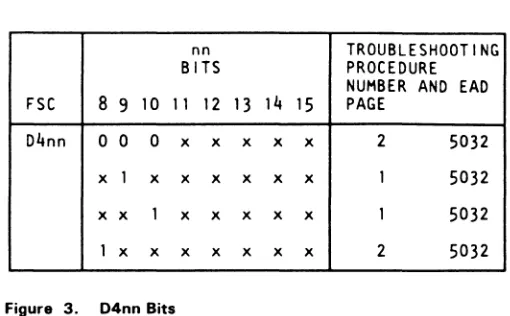
II :SCI.:;'" 0lie 0 e ... ual .... ---"
76 • tension established 73 • load/unload in progress
3480MI EC
C137~~C'lCoJlyright IBM Corp. 1982. 1991
I
1I
I
I
I
I
Additional Actions/Comments
See OPER 1 tor "Tape Unloading-Unload." TeC FRUs associated With thiS error COlle are:
2679 • 02A·A 1 B2Y 268" • 02A·A 1 B2Z
Use the EAD for CHK 26 for failure Isolation. See EAD 1
tor "CHK 26" or "CHK 31."
TCC FRUs associated With thiS error coce are: 2Sr • 02A·A1 B2Y 268"· 02A·A1 B2Z
ThiS error may occur If the coce has not !:leen loaded to tr'Ie automatic cartridge loader.
i None
I
I
None
I
IBM Ennanced Capacity Cartridge System tapes should not be mounted in a 3480 SUbsystem.
I
IBM Enhanced Capacity Cartridge Syste[J1 tapes shOuld not be mounted in a 3480 subsystem.
See OPER 1 tor "Drive ContrOl Card."
TCC FRUs aSSOCiated with thiS error COde are:
26r . 02A·A 1 B2Y 268· • 02A·A 1 B2Z
I
Use the EAD for CHK 41 for rallure ISOlation. See :AD 1 for 'CHK 41."
TCC FRUs associated With this error COde are:
26r . 02A-A 1 B2Y 2689 • 02A·A 1 B2Z
c c
e
e
c
e
c
I
FftU FftU Name
I
HUM • EC Sensitive Fftu. S . . CARR·OR 4 .. EC Sensitive FftU. See CARR-CU7
232 Cartridge I
001 Threader assembly
13r
30'7
z..
003 File reel motor
'?5
J.