VOLUME -2, ISSUE -4 (JUNE 2014) ISSN: (2321-1717)
ROBOT BASED OBJECT IDENTIFICATION
Someet Singh, Assistant Professor,
Electronics and Communication Department Lovely Professional University,
Jalandhar, India
Navjot Kaur, Assistant Professor, Computer Science & Engineering
Department,
SBBSIET, Jalandhar, India.
ABSTRACT
In this paper, a new approach for detecting and matching the overlapping symmetric and
asymmetric real objects and multiple patterns obtained in various views using an automated
robot sensing is proposed. The proposed system introduces a system supervising using sensors
and a webcam or mobile camera to record, transmit and analyze the objects. The goal of the
proposed system is to recognize the identity, position, and orientation of randomly oriented
objects. In order to identify and match the symmetric and asymmetric overlapping objects, an
automated robot must be equipped with a set of sensors that provide information about the
presence of a matching object around.
Keywords: Object Identification, Feature Extraction, Robot Sensing, Pattern Matching, Robot Vision.
INTRODUCTION
Robot vision is an interesting and rapidly growing field. The Robots are used in several places
which are helping humans in several aspects of life. The rapid progress has reduced the coverage
of less significant areas. The main focus is to develop simple descriptions from captured and
sensed images using some automated system. To recognize an object refers to fact of assigning a
set of symmetric, asymmetric overlapping point to the known classes for identification.
Autonomous robots operating in human environments give some extremely challenging research
topics in planning and dynamic perception whether it is in any field the workplace, a play ground
or in a household. In order to navigate and interact with, such an environment, accurate and
VOLUME -2, ISSUE -4 (JUNE 2014) ISSN: (2321-1717)
Predicting shapes represents an important domain of recognizing image objects, based on theirshape information and object characteristics. [1] The identification of the object by efficient and
accurate automated system for connected or overlapping objects in an image leads to the
decreased execution time and elapsed time. Each sensed image contains up to several hundred
objects, which were manually arranged not to overlap or touch each other. The proposed
approach is divided into three stages. In the first stage the robot will capture the image and will
send the image to the main computer, in this stage multiple thresh-holding values for the image
are defined. Over segmentation and erosion is applied on binary image to erode away the
boundaries of regions of foreground pixels.[9] match the object with prescribed dimensions. In
the second stage features of the current object whose user is going to predict the shape are
matched with the preloaded features in data set of known classes.[7] in the Third stage, the
equivalence distance to which the current object matched in data set is considered. In this stage,
the robot will move towards the identified object, the distance travelled by the robot to capture
the object depends upon the diameter of the wheel of the robot. Robot will bring the required
object to the player.
MORPHOLOGY
The term Morphology refers to set of image processing operations that process images based on
shapes. Morphological operations apply a structuring element to an input image, creating an
output image of the same size. In a morphological operation, the value of each pixel in the output
image is based on a comparison of the corresponding pixel in the input image with its neighbors.
By choosing the size and shape of the neighborhood, you can construct a morphological operation
that is sensitive to specific shapes in the input image.[2] Morphological operations affect the
structure or shape of an object. All these operations are applied on binary images.
STRUCTURING ELEMENT
Structuring element consists of matrix of 0’s and 1’s. Its size is smaller than the image and its
origin identifies the pixel to be processed. The structuring element used for processing the images
VOLUME -2, ISSUE -4 (JUNE 2014) ISSN: (2321-1717)
If A and B be two sets in Z2 then,A + B = {| (B)z ∩ A ≠ ϕ }
Where A is image and B is the structural element.
MORPHOLOGICAL OPERATIONS
The two principal morphological operations are dilation and erosion. The proposed work is based
on the implementation of erosion on to extract features of objects.
EROSION
Erosion shrinks objects by etching away (eroding) their boundaries. When using erosion
structural element also passes through all pixels of the image.[4] if at a certain position every
single pixel structuring element coincides with a single pixel binary image, then the logical
disjunction of the central pixel structuring element with the corresponding pixel in the output
image. The method of erosion for prediction of overlapping and connecting images is specially
used in this algorithm to increase the efficiency and improve execution time.
a + b = {z | [ (b)z ɛ a]+
Where a is an image and b is structuring element in z2.
FUZZY LOGIC
A fuzzy system is represented by if-then rules in the form:
if i1 is vi1,1 and … and im is vim,1
then o1 is vo1,1 and … and on is von,1
VOLUME -2, ISSUE -4 (JUNE 2014) ISSN: (2321-1717)
which is an exponential function of the number of the inputs i and the number of linguistic valuesl taken by input.
r = li
if a fuzzy system has n inputs and single output then its fuzzy rules can be of the form:
if x1 is a1j and x2 is a2j … and xm is ajm
then y is bj
Dataset
It is a collection of data elements. The following name/value pairs are used when a dataset is
constructed:
1. varnames: this gives the variableswith the specified variable names.
{name_1,...,name_m}
2. obsnames: this gives the nobservations in a with the specified observation names.
{name_1,...,name_n}
II. OPERATIONAL STAGES
The proposed technique is to identify the expected object using a robot on the basis of estimated
values for dependent variables from previously unseen predictor values based on the variation in
a learning database are used to predict the objects in the shape. Main focus of work is to predict
the shape by using a automated machine on the basis of defining morphological operation which
describes all boundary points of a shape. Prediction of the object by an automated efficient,
accurate, computationally fast and invariant technique for connected or overlapping objects in an
VOLUME -2, ISSUE -4 (JUNE 2014) ISSN: (2321-1717)
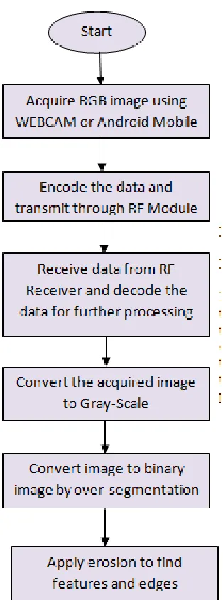
BASIC STEPS
Figure 1: Basic Steps
Levels of Proposed Technique:
In the first stage the robot will capture the image and will send the image to the main computer, in
this stage multiple thresh-holding values for the image are defined. Over segmentation and
erosion is applied on binary image to erode away the boundaries of regions of foreground
pixels.[9] match the object with prescribed dimensions.
LEVEL I
I. Acquire Image: First step is to ACQUIRE AN RGB image USING WEBCAM OR
ANDROID MOBILE and convert that image to gray scale image by defining
multi-thresholding.
VOLUME -2, ISSUE -4 (JUNE 2014) ISSN: (2321-1717)
III. Erosion: Apply erosion on binary image to erode away the boundaries of regions of
foreground pixels.
IV. Feature finding: Find the features and edges for the current image with the help of fuzzy
logic operations and will be loaded into memory for use whenever it is needed.
[image:6.612.233.390.198.620.2]Working Steps for Level I
Figure 2: Working Steps for Level I
VOLUME -2, ISSUE -4 (JUNE 2014) ISSN: (2321-1717)
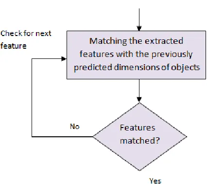
In the second stage features of the current object whose user is going to predict the shape arematched with the preloaded features in data set of known classes.
[image:7.612.198.411.191.380.2]Working Steps for Level II
Figure 3: Working Steps for Level II
LEVEL III
In the Third stage, the equivalence distance to which the current object matched in data set is
considered. In this stage, the robot will move towards the identified object, the distance travelled
by the robot to capture the object depends upon the diameter of the wheel of the robot. Robot will
bring the required object to the player.
VOLUME -2, ISSUE -4 (JUNE 2014) ISSN: (2321-1717)
Figure 4: Working Steps for Level III
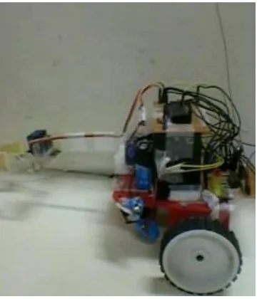
III. EXPERIMENT SETUP
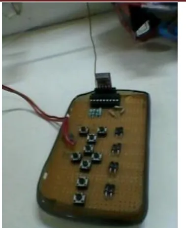
[image:8.612.216.396.368.578.2]VOLUME -2, ISSUE -4 (JUNE 2014) ISSN: (2321-1717)
Figure 6: Remote to control the functionalities of IMGROB robot
IV. RESULTS
For the purpose of testing the experimental results, different input values are considered and the
results obtained from the IMGROB robot are graphically analyzed.
Table1: Table imgrobtbl for the predicted time values
Objects
per
capture
d
image
Time taken for predicting the
objects Tria ngle Rect angl e Ecli pse Cir cle Poly gon
10 5.22 5.28 5.43 5.7
7
6.18
13 7.21 7.22 7.50 7.8
6
VOLUME -2, ISSUE -4 (JUNE 2014) ISSN: (2321-1717)
15 8.60 8.62 8.75 9.1
3
9.72
22 29.4
9
23.2
0
13.2
4
13.
94
33.5
0
The predicted time values Table1 above shows the predicted values for time which may vary
depending upon the distance among objects of input images and number of objects per image.
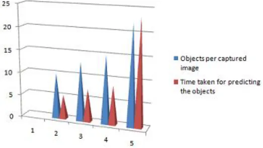
1. Output surface for Triangular shaped objects by robot
Figure 7: Output surface for Triangular shaped objects by robot
Figure 8: Point description of Triangular shaped identified objects
This output surface shows the variation in the values of triangle predicted in all the images. The
predicted values vary as the number of objects in the image increases.
VOLUME -2, ISSUE -4 (JUNE 2014) ISSN: (2321-1717)
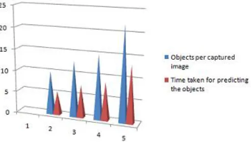
Figure 9: Output surface for Rectangular shaped objects by robot
Figure 10: Point description of Rectangular shaped identified objects
This output surface shows the variation in the values of rectangle predicted in all the images.
The predicted values vary as the number of objects in the image increases.
[image:11.612.184.445.279.426.2]VOLUME -2, ISSUE -4 (JUNE 2014) ISSN: (2321-1717)
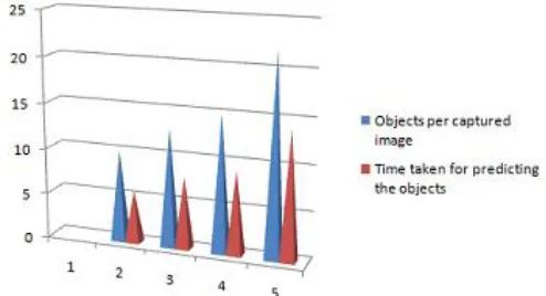
Figure 11: Output surface for Eclipse shaped objects by robot
Figure 12: Point description of Eclipse shaped identified objects
This output surface shows the variation in the values of eclipse predicted in all the images.
The predicted values vary as the number of objects in the image increases.
[image:12.612.68.521.529.707.2]VOLUME -2, ISSUE -4 (JUNE 2014) ISSN: (2321-1717)
[image:13.612.198.445.110.244.2]Figure 13: Output surface for Circular shaped objects by robot
Figure 14: Point description of Circular shaped identified objects
This output surface shows the variation in the values of circle predicted in all the images.
The predicted values vary as the number of objects in the image increases.
5. Output surface for Polygon shaped objects by robot
[image:13.612.198.446.371.518.2]Figure 15: Output surface for Polygon shaped objects by robot
VOLUME -2, ISSUE -4 (JUNE 2014) ISSN: (2321-1717)
This output surface shows the variation in the values of polygon predicted in all the images. Thepredicted values vary as the number of objects in the image increases.
V. CONCLUSION AND FUTURE SCOPE
The proposed technique is an efficient technique for identifying the common objects which may
be present in any play ground. The idea proposed is based on the fact that the designed robot is
capable to identify even the adjoining or overlapping objects correctly. The proposed work can be
extended to do and enhance Image definition to define the image based on characteristics of
objects predicted.
REFERENCES :
[1] Collet, A., Berenson, D., Srinivasa, S., Ferguson, D. “Object Recognition and Full Pose Registration from a Single Image for Robotic Manipulation”.
[2] Kaur, N., Singh, S., Kundra, S., 2013, “Algorithm for object recognition”, American International Journal of Research in Science, Technology, Engineering & Mathematics, pp 108-113.
[3] N.Kaur, S. Kundra, H. Kundra, “Shape Prediction Linear Algorithm Using Fuzzy,” International Journal of Advanced Computer Science and Applications, Vol. 3, No. 10, 2012 [4] Wang, R., Bu, F., Jin H., and Li, L., 2007.“Toe shape recognition algorithm based on fuzzy neural networks”, IEEE International conference on Natural Computation, vol. 2, pp. 737-741. [5] Kumar, S., Kumar, V., 2013. “ Alive Human Detection Robot Using Image Acquisition and Processing”, International Global Research Analysis, vol. 2 issue: 11, pp 70-72.
[6] S. Ekvall, D. Kragic, and F. Hoffmann, 2005. “Object recognition and pose estimation using color cooccurrence histograms and geometric modeling,” Image Vision Comput., vol. 23, no. 11, pp. 943–955.
[7] Yuan, W., Jing, L. 2011. “Hand-Shape Feature Selection and Recognition Performance Analysis”, IEEE conference, ichb, pp. 1-6.
[8] Baloch, S. and Krim, H., 2010. “Object Recognition through Topo-Geometric Shape Models Using Error-Tolerant Subgraph Isomorphisms”, IEEE Transactions On Image Processing, vol. 19, issue. 5, pp. 1191-1200.
[9] D. Berenson, S. Srinivasa, D. Ferguson, A. Collet, and J. Kuffner, 2009. “Manipulation planning with workspace goal regions,” in IEEE Int’lConf. on Robotics and Automation (ICRA’2009),Kobe,Japan.
[10] Shoval, S., Borenstein, J., 2001. “Measuring The Relative Position And Orientation