Development of PLC based Automatic Prototype Cutting Machine
Harshitha R
1Dr. M. S. Srinath
21
PG Student
2Professor
1,2
Department of Industrial Automation Engineering
1,2
Malnad College of Engineering, Hassan, India
Abstract— Cutting is a compressive and shearing phenomenon, where cutting a materials like paper, timber, pipes to the required length in any manufacturing industry is the initial step. Increasing in Global competition and technological advances are forcing manufactures designers and engineers rapidly produce strategies decreasing products development cost and time. Manufactures who exit at a same time have the option of selecting optimum technologies or processes to coincide with their manufacturing surrounding. The main idea of this work is to design a prototype model for automating the cutting process for varying length in continuous cutting process with reduced time and cost which may applicable in industry. Programmable Logic controller (PLC) and Human Machine Interface (HMI) is used to propose new approach, HMI is designed to enter the values like length, rpm, number of counts and HMI is connected to PLC by RS485 serial communication protocol. PLC is programmed to control the servo motor where entered values are converted to pulses and when targeted length is reached PLC will actuate pneumatic press to cut the paper to solve the problem of continuous cutting process for varying length.
Key words: HMI, PLC, RS485
I. INTRODUCTION
The word manufacturing may have coined recently but the process of manufacturing is there since the inception of technology. Cost reduction seems to be today’s new way of approach in the manufacturing community. The total product cost is influenced by two major elements i.e. Material and manufacturing cost. In any manufacturing industry cutting is usually used to fit several components of large size to most favorable material standard sizes. A shift growth in recent modernization and automation of manufacturing technology has urged an accurate and economical system to give a perfect finish to the product developed.
Machining is a term that covers a large collection of manufacturing processes designed to remove unwanted material, usually in the form of chips, from a work-piece. Machining is used to convert castings, forgings, or preformed blocks of metal into desired shapes, with size and finish specified to fulfill design requirements. Almost every manufactured product has components that require machining, often to great precision. The majority of industrial applications of machining are in metals. Although the metal cutting process has resisted theoretical analysis because of its complexity, the application of these processes in the industrial world is widespread. Metal cutting processes can be viewed as consisting of independent input variables, dependent variables, and independent dependent interactions or relationships. The engineer or machine tool operator has direct control over the input variables and can
specify or select them when setting up the machining process. Several input variables are described below.
A. Background and Motivation
If cutting is carried out at the design stage the manufacturing engineer has higher probability of making the best usage of the materials. To get maximum benefits in material cost reduction and lead time reduction automation of process is required. Cutting is the part of design process and Programmable Logic Controller (PLC) and Human Machine Interface (HMI) is used to control the cutting process which is main part of the manufacturing industries. Each and every part of the design that leads to the final cost is examined, and appropriate remedies are taken to prevent to those unwanted and expensive elements before it approach to the final designs.
B. Automation of Manufacturing Process
Automation or programmed control is the utilization of different control frameworks for operating equipments such as machineries and processes in factories with negligible or decreased human intercession. Some process have been completely automated some semi-automated, the biggest advantage automation is to save labors time, save energy and materials and to improved quality, accuracy and precision. This work aims to guide the increased accuracy and precision of the paper cutting profile where paper is cut to exact length and number of counts which is achieved by programmable logic control (PLC).
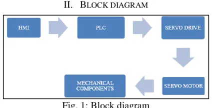
[image:1.595.322.535.480.588.2]II. BLOCK DIAGRAM
Fig. 1: Block diagram
This part of the report explains in detail about cutting process which has been designed assembled, powered, programmed and analyzed. The emphasis is given to core principles involved in running the machine. Cutting refers to the process of deposit cutting patterns to minimize the raw material size like sheet metal and paper etc. Several approaches in controlling and synchronization have also been put forward. The control system has been used effectively during the process.
background activity of system i.e., between its input and output. The proposed prototype model is as shown in the block diagram [Fig 1]. The major components required in the present model are HMI, PLC, servo drive, servo motor, and pneumatic actuator.
III. HARDWARE IMPLEMENTATION
A. Human Machine Interface HMI
Human Machine Interface is a high performance touch performance touch screen machine control interface for industrial application and also acts as an interface between human and machine. HMI is designed to reach the rapidly increasing difficult process of the machines and systems. HMI is designed to reach the specific Human Machine Interface needs with the help of open and standardized interface in hardware and software, which allows in the perfect merge into the automation systems.
HMI Human Machine Interface is designed and installed through the software called vijeo design software. HMI is connected to PLC through connection bus called as modbus RS 485, and here PLC is designed using So Machine Basic software which then perk up the servo drive and controls the motor as entered in HMI. Mechanical equipment like single acting pneumatic cylinder switched on to cut the paper to the required length.
Fig. 2: Schneider HMI(HMIGXU3512)
B. Programmable Logic Controller (PLC)
Programmable Logic Controller also called as programmable controller is a digital computer used for controlling of machinery on factory assembly line. PLC is an industrial computer control system that continuously looks after the condition of input devices and makes the decision based upon the custom program to control the condition of output devices.
[image:2.595.54.533.323.500.2]It was first developed in the automobile industry to provide flexible, shock-resistance and easily programmable controllers to replace hard-wired relays and timers. Since then they have been widely used as highly-trusted automation controllers applicable for harsh environments. It converts the values into pulses as per the program. PLC send command to the servo driver to command AC servo to rotate to the prescribed speed and number of rotations.
Fig. 3: Schneider PLC (TM200C40U)
The PLC used here is TM200C40U where M200 is
and u stands for transistor which produces high speed. It shows the architecture how PLC connected to HMI and servo motors. HMI is connected through serial link RS485. Programming for this PLC is done using SoMachine Basic software using ladder diagram and installed to PLC using USB key or Ethernet.
C. Motor Synchronization
A servo drive is a unique electronic enhancer used to control electric servo components. A servo drive monitors the feedback signal from the servomechanism and consistently modifies for deviation from expected behavior.
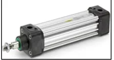
[image:2.595.59.276.630.758.2]A servo motor is a rotating actuator or direct actuator that takes into account exact control of angular or straight position, velocity and acceleration. It comprises of an appropriate motor coupled to a sensor for position input. The motors are driven by frequency converter, which takes signals from PLC controller. The speed and position of length to cut is given directly by HMI. The values entered by HMI are the input to the PLC where the given values are converted to the pulses at output. The controller compares the output values with the required value and gives correction signals if any error presents.
Fig. 4: Servo Set (LXM23DU)
D. Mechanical Perception
As the machine used to cut the paper, importance is given to the length drawn to cut. The paper is drawn with the help of motor shaft which is controlled by Programmable Logic Controller (PLC). TM200C40U used here. The features and technologies used in this system makes highly flexible and versatile and also reduce cutter position changeover time to very acceptable level.
[image:2.595.371.488.700.761.2]IV. SOFTWARE USED
A. Vijeo Designer Basic Designing
[image:3.595.54.486.72.754.2]The main window of Vijeo Designer Basics is as shown in (Fig. 6). And it is followed by the procedure to use the software to design the HMI.
Fig. 6: Vijeo Designer Basic Main Window Steps to Run the Software
1) Create new project – in iq manager create new driver - select modbus equipment – com
Fig. 7: Create New Project Window
2) The required panels for the model is created as shown in the below Figures
[image:3.595.287.543.73.489.2]a) Figure shows the welcome window
Fig. 8: Welcoming window
[image:3.595.311.546.88.288.2]b) Below (Fig.9) shows the menu of the cutting machine which run in two mode i.e auto mode and manual mode
[image:3.595.46.292.118.319.2]Fig. 9: Menu of the cutting machine which run in two mode c) Below (Fig 10) shows auto mode panel where required length, speed and numbers of count required.
Fig. 10: Auto Mode Panel
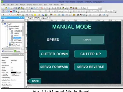
d) Below (Fig.11) shows the manual mode panel where the cutter position, servo motor rotation is manually done it involves the push button operation.
[image:3.595.306.553.512.696.2]e) Below figure shows the settings panel where this step is done first before starting the operation and here can adjust the required pulses per minute can be added
Fig. 12: Settings Panel
B. PLC Programming
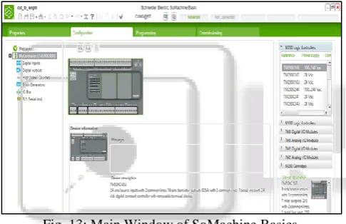
The main window is as in the figure 13. Here before programming, configuration of PLC model is selected, type of pulse generators
Fig. 13: Main Window of SoMachine Basics.
V. RESULTS
The method of extraction of result and analysis of data is done here. The parameters considered for this purpose are as followed:
Cut off length Speed of rotation Pulses per rotation
Servomotor is connected to below roller which helps to rotate. Another roller is adjustable where the gap between the two rollers can be adjusted to the thickness of the paper. The HMI is placed above where the values like length, how many counts are required, at what speed servo motor has to rotate. As long as the motor rotates paper is drawn and pneumatic actuator is placed next to the roller, once the paper for given length drawn pneumatic cutter helps to cut the paper. Pneumatic actuator used here because of maintaining accuracy and precision.
[image:4.595.46.287.89.267.2]Figure 14 shows the complete electrical connection for the model. Where PLC input is connected to SMPS and PLC output is connected to servo terminal block.
Fig. 14: Electric Panel
For changing in parameter like varying length several trails are carried out from 10mm to 100mm for number of counts done on this machine. By entering the required length through HMI, the output signals from HMI is input to the PLC where length is converted to pulses. HMI is used to interface and PLC is used as controller, and servo motor generate pulses.
VI. CONCLUSION
As coated in literature survey cutting is a continuous mass production technique, the cutting process contributes about 80% in manufacturing of product in manufacturing sectors like paper industry. Hence the work place a major part in this field. Here, to cut a paper of varying parameter like length and different number of counts a system is developed and analysed. This analysis is achieved by using human-machine interface (HMI), Programmable Logic Controller (PLC), and servo motor and single acting pneumatic is used since it uses compressed air and main advantage is there will be no oil leakage, which reduces cost and time lost in tool change. The system developed can cut the papers for given length by converting it to pulses in mimum time and given number of counts. That results in lead time reduction and reduced manpower which intern increases throughput.
VII. SCOPE FOR FUTURE WORK
This work can be established in all the manufacturing sectors for reduced inventory, and for the better performance with increased accuracy. By using Programmable Logic Controller (PLC) any process can be automated by writing the program for the process. Any raw materials like rubber, lather or timbers can cut within a minimum time, with more efficiency.
REFERENCES
[1] Indrajit Mukherjee and Pradip Kumar Ray “A review of optimization techniques in metal cutting processes”, Journal of computer and industrial Engineering, 2006, Vol. 50, pp. 15-34.
[2] Vijay Kumar U, Ghanshyam Kumar, Dharesh Bansod, Deepak Sahu, Rishabh Bendre, and Aakanksha Suryawanshi, “Design and Analysis of Paper Cutting Machine works on Geneva Mechanism”, IJARIIE, 2016, Vol. 2, pp. 245-276.
[image:4.595.46.289.323.480.2][4] Thomas Brunsch, Laurent Hardouin and J¨Org Raisch. “Modeling and Control of Nested Manufacturing Processes Using Dioid Models”, Journal of IEEE, 2011, Vol. 4, pp. 978- 989.
[5] Qi Yue and Shan Liang, “Research on the Application of Genetic Algorithm for the Panel Cutting Stock”, Journal of IEEE, 2011, Vol. 4, pp. 246-257.
[6] Vyacheslav Kharchenko, Anastasiya Orekhova and Alexandr Orekhov, “Human-Machine Interface Quality Assessment Techniques: Green and Safety Issues”, IEEE, 2014, Vol. 4, pp. 141-152
[7] Christopher Martin, Matthias Freund, Annerose Braune, Ralf-Erik Ebert, Matthias Plebow, Sven Severin and Oliver Stern, “Integrated Design of Human-Machine Interfaces for Production Plants”, IEEE, 2015, Vol. 3, pp. 260-282
[8] Gong Xiu-Lian, Huang Qing-Xue and Li Hong-Jie, “Research and Application of a New Cut to Length Model of Rolling Shear”, IEEE, 2009, Vol. 5, pp. 144-148.
[9] Weihua Jiang, Ruiming Yu and Hao Wang, “Design of Servo Positioning Control System for Graphite Spraying Machine”, Journal Of IEEE, 2011, Vol. 2, pp. 162-175.