(IoT) Focus Group, Faculty of Electrical and Electronic
Engineering. This book chapter is an introduction to a
number of the topics in Internet of Things (IoT),
which focusing on the tracking and monitoring
systems. All topics described the design and system
development related to IoT. The presented topics
have been selected to give an idea to engineering
students in order to design the IoT systems. This book
chapter is generally suitable as complement to
integrated
design
and
final
year
project
of
engineering students.
SHARIFAH SAON
Preface
iii
Chapter 1 e-Commerce Stock Inventory via ScanCart: The Android Barcode Scanner
Sharifah Saon, Abd Kadir Mahamad, Muzammil Mudzakir
1
Chapter 2 Barcode Document Tracking System
Soon Jian Cheng, Abd Kadir Mahamad, Sharifah Saon, Mohd Anuaruddin Ahmadon, Shingo Yamaguchi
13
Chapter 3 An Early Warning Elephant Intrusion Integrated with IoT
Mohd Zulhafizie, Fauziahanim Che Seman
29
Chapter 4 Flood Detection and Mitigition System Using SMS Notifications
Muhamad Nabil Asyraf Ghazali, Ansar Jamil, Jiwa Abdullah, Lukman Hanif Muhammad Audah, Rozlan Alias
39
Chapter 5 Smart Home Automation System using Internet of Thing (IoT)
Noorsaliza Abdullah, Norshidah Katiran, Ezri Mohd
55
Chapter 6 Integrated Outdoor and Indoor Tracking Through GPS, LTE and Wi-Fi Solution
Seh Bee Yan, Fauziahanim Che Seman
63
Chapter 7 IoT Based Security System for a One Bed Hospital Room
Mohammad Nazri Rosli, Lukman Hanif Muhammad Audah, Nor Shahida Mohd Shah
73
Chapter 8 Development of Anti-Theft Monitoring System in IoT Environment
Farhana Ahmad Poad, Jusrorizal Fadly Jusoh, Muhammad Iqmal A Ghani
87
Chapter 9 Fire Alarm Smart System Technology (FASTech)
Sharifah Saon, Amirrul Atiman, Abd Kadir Mahamad
Chapter 7
IoT Based Security System For A One Bed Hospital
Room
Mohammad Nazri Rosli, Lukman Audah, Nor Shahida Mohd Shah
1.1
Introduction
The use of hospital facilities, whether in private or government
hospitals is increasing and most of it involve serious cases until some
of the patients need to be detained in the hospital for further
examinations and continued monitoring from the doctor. Therefore,
hospital rooms are often full with patients and visitors [1]. This may
cause lack of attention and awareness from the authorities. So, the
authorities should seek some alternatives in order to overcome this
problem by creating or using devices that could be used by patients or
caregivers.
Based on previous related studies, there are some other advanced
technology security systems being applied in hospital security system.
One of the examples is the nurse call button system as shown in
Figure 1. It works with an ontology that specifies for each risk factor a
probability, which indicates the similarities of the patient and the risk
Figure 1: General concept of nurse call system [2].
The patient can go anywhere he wants in the hospital areas as long as
the wireless call button is with them. This button will send a signal that
triggers a message which will be received by the nearby sensors. There
are many available sensors all over the place so there will be no error.
Even if one of the sensors is not functioning, there are other nearby
sensors which can receive the signal from the push button. This signal
will be sent through the switch to the back-end server [3] [4].
In order to achieve system efficiency, information about the profiles of
the patients and staff members should be linked together. Ontologies
The Monitoring Component always monitors the ontology to pick up
trends and patterns in the way the priorities are assigned by the
caregivers.
This component stores the information and data in the Persistence
Layer. This data can be inspected by the experts by using the
Configuration Module. When enough data and information has been
collected, the Learning Pipeline can be initiated by the Configuration
Module. The Configuration Module is being notified of which data
should be collected for the Learning Pipeline, either by the Monitoring
Component or by the domain experts and administrator. The latter
allows the initiation of the Learning Pipeline with external data
provided by the stake holders. As shown in Figure 2, the Configuration
Module configures the Pipeline Manager to use the Data Collection
Component, Input Convertor and Integration Component that suit this
type of evidence. It also passes the correct parameters to the Pipeline
Manager, which are needed to retrieve the data from the Persistence
Layer using the Data Collection Component [5].
The Learning Pipeline is implemented by using the Pipes-and- Filters
architectural design pattern [6]. A pipeline consists of a set of filters,
implementing small processing steps, which are connected by pipes. All
rearranged, omitted or added. In this way, an extensible and flexible
[image:6.420.58.363.133.361.2]architecture is achieved.
Figure 2: A self-learning component [2].
For the security notification system, one of the projects that has been
done is a project that implements a door lock system as shown in
Figure 3 which communicates through internet platform (IoT). As the
process stage, the microcontroller will process all the data sent through
it. Equipped with Wi-Fi dongle, the way of communication can be made
Besides that, it is also provided with mailing and tweeting
accommodations. [6].
Basically, all of these systems still utilizing LAN connection or offline
mode which the data can only be received with the utilizer who has
connection with the server. Nurse call buttons which are located or
annexed at the wall or in the toilet still do not give full security
[image:7.420.70.381.245.331.2]quantification and accommodations [7].
Figure 3: Security notification system block diagram [6].
1.2
Methodology
For the project methodology, this system was firstly built by designing
the system. The idea came out when the Internet of things (IoT) was
first became famous in Malaysia. Integration of IoT in the hospital
security system will benefit many people. In order to make the system
successful, hardware and software needed to be required. In software
application chosen were important in order to make sure that the system
was a success. In the hardware part, the right combination of sensor,
microcontroller and output software/hardware made the system easier
to be developed as shown in Figure 4. At last, both software and
[image:8.420.95.365.188.306.2]hardware were combined and in the end, the analysis was made.
Figure 4: Project system architecture.
1.2.1
Application Services
The application services service is an important medium to connect
users to the website created by them. For this project
http://instapush.im/ was used as an application for this project. The
Instapush, is an application that can provide push-notification services
between the controller and user through internet connection. This
application was suitable to be used in this project because it provided
controller with the server. Figure 5 shows the instapush web application
[image:9.420.53.372.127.237.2]website.
Figure 5: Instapush web application.
The ‘push message’ had to be programmed as the message that was
going to be sent to the user. It was then linked to the tracker status so
that it would appear in the push notification message correctly. For an example, if the tracker was programmed as ‘status’ then the push massage would have been notified to link the trackers as ‘{status}’. In
order to connect the web application with the controller program, it
could only be done inside the controller program.
Another web service application was a RETE IoT platform which was
used as the medium to connect the CHATFuel application with
the microcontroller API with the chatfuel application. Figure 6 shows
[image:10.420.54.373.130.277.2]the chatfuelJSON API application.
Figure 6: ChatfuelJSON API application.
From Figure 6, there are some function blocks referring the situation
needed by the user. For this system, illustrated in the Figure 6, each
block was built for both emergency protocol and no emergency protocol
which will be linked with the hardware using JSON API console. Using
RETE IoT application, the blocks of both situations were stated in two
1.2.2
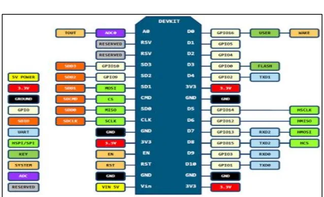
Microcontroller
The NodeMCU is a combination of Arduino UNO and ESP8266 that
provided access to the GPIO (General Purpose Input/Output)
[image:11.420.53.372.164.358.2]subsystem.
Figure 7: NodeMCU description.
In this project, the connection between the microcontroller and the
application had to be made through the program. Arduino IDE provided
a programming tool through Arduino IDE application as shown in
Figure 7. All the project programs were coded and compiled before
For this project, the pins used were the Vin and GND buttons, which
were used for the voltage supply to turn on the microcontroller. Pin D5,
GND and 3V3 were used to connect the microcontroller to the sensor.
For pull-up connection, the 3V3 had to be connected to the input pin so
it could control the microcontroller, either to be switched ON or OFF.
Digital 5 pin was chosen as the sensor pin because the pin was located
near to the ground and voltage pin, so it was easy to make a pull up
connection.
The controller had to make a HTTP request, which used ESP 8266 as
the user agent. The host for this application had already fixed which was the ‘api.instapush.im’. If the application accepted this request, it
would have read the instapush app-id (ID) and also the instapush secret
(password). For this project program, it only triggered notification once
at a time. This means that the controller only triggered the output once
after it had been switch on. This project was programmed in this way
so that it could reset the connection each time after it triggered the
output for better connection and real-time data execution.
1.3
Results and Discussion
The push notification was sent when the sensor was triggered.
However, there was some time delay before the application received
internet network speed. The faster the internet connection, the less the
[image:13.420.92.327.128.260.2]delay would be.
Figure 8: Push notification prototype.
Figure 8 shows the push notification circuit. It is small enough to be a
[image:13.420.72.348.358.493.2]portable prototype and can be used by the patient.
Figure 9 shows the nurse call system prototype which consists of one
input and two outputs. The outputs were the light emitting diode (LED)
and also the buzzer. Both of these outputs were enough to trigger the
doctor in charged.
The web service application could be accessed through the website and
also a smartphone. Figure 10 shows the instapush output from the
[image:14.420.55.364.246.399.2]website application.
Figure 10: Instapush website output notification.
In instapush web application, the notification output was sent for both
of the applications; the website and also the smart phone application.
The difference between both outputs was that the push notification from
Meanwhile, in the web-service application, the page needed to be
reloaded or refreshed in order to receive the notification.
Instapush application provided real time push notification. Using
NodeMCU as the microcontroller, the sensors which were the reed
switch and push button that switched the prototype on and off. For
security door system, when the door closed, the pull-up connection on
the NodeMCU switched off the microcontroller. When the door
opened, the microcontroller was switched on, connecting it to the
Wi-Fi. Then the system was connected to the instapush server before the
push notification signal was sent to the GUI application. After the push
notification had been sent, the system closed the connection with the
server but the microcontroller was still connected to the Wi-Fi. It took
some time for the microcontroller to connect to the server. So, the
sensor should not be pushed many times as it would reset the
connection. It also delayed the connection between the microcontroller,
the Wi-Fi and the Instapush server.
The same process happened with the push button system. The
difference is, when the push button was pressed, the pull-up connection
switched off the Microcontroller until the push button was released. As
the push button was released, it reset the connection of the
microcontroller to the server and resent the signal to the server for push
Different process happened to the nurse-call-system. The nurse call
system used Facebook messenger to send a signal to the
microcontroller, light up the LED and switch the buzzer on. The process
happened as mentioned in previous chapter. It was used to notify the
doctor that he was needed in the ward. The prototype was portable and
could be carried anywhere as long as it had its registered Wi-Fi
connection. The voltage entering the circuit was 3.04V and enough to
[image:16.420.54.361.245.400.2]supply the output of the circuit as illustrated in Figure 11.
Figure 11: Operating voltage for nurse call system.
In order to make sure that the circuit was stable and safe to be used, the
analysis of the circuit power supply was using oscilloscope. In order to
operate this system, a maximum of 5V of DC power supply was used.
power supply was low so it was more suitable to be used as a portable
[image:17.420.54.363.130.276.2]device.
Figure 12: Voltage supply for the push notification system circuit.
2.
Figure 12 shows the voltage flow from the microcontroller which was
operated in 3.4V and was enough to send a signal to cloud. Meanwhile,
Figure 10 shows the nurse call system voltage supply of 3.04V. When
the signal was sent from the Facebook messenger, it triggered a signal
to the microcontroller. The microcontroller then provided 3.04V into
the outputs which were the LED and buzzer. The system did not stop
until the cancel button was triggered from the transmitter. It was
continuously looping and it could only be stopped when the user called
Basically, the range of connection depended on the Wi-Fi router. In this
situation, the router of D-Link DSL-2750EADSL2+ 4 Port Wireless N
300M Router Modem (2 x 5dBi Antenna) was used. The results of the
[image:18.420.132.288.188.440.2]connection test are as shown in Table 1.
Table 1: Table of the connection versus the distance.
For the sensor sensitivity, Reed switches are a mechanical device
with magnetic moving parts. It consists of two ferromagnetic wires Distance (meter) Connection
separated by a small gap. In the presence of a magnetic field that is
parallel to those wires, they will touch each other, making electrical
contact. In other words, the magnetic axis of the magnet should be
parallel to the long axis of the reed switch. The range of sensitivity
depends on the tolerance of the magnetic field between those sensors.
[image:19.420.136.282.223.416.2]In this project, the range of sensitivity is shown in Table 2.
Table 2: Graph of reed switch sensitivity.
Distance (cm) States
0.2 Off 0.4 Off 0.6 Off 0.8 Off 1.0 Off 1.2 Off 1.4 Off 1.6 On 1.8 On
In this project, the limitation of the project was the Wi-Fi connection.
From the analysis above, it shows that the distance of the project and
the Wi-Fi router affected the prototype process. Wi-Fi router distance
Secondly, the security of the internet-of-thing (IoT) still remains as the
limitation in every IoT project. The security system is easily breached.
In future study, the security of the system needs to be enhanced because
it is connected to the safety of the patient itself.
Thirdly, the data storage (cloud storage) was not too specific in this
project. It means that the data storage in terms of the period of the
transducer used and the number of user are important in order to
enhance the security itself. In case of emergency, the data plays as the
most important role to every investigation. Single bedrooms are privacy
rooms created for special patients. There is no other visual monitoring
except for the caretaker and in-charged hospital staff. So the data is
important in any case of emergency.
Then, the project sensor had its own limitation. The sensor could not be
used in short period of time as it took time to connect with the server.
In pull up connection, the sensor toggled the states of the
microcontroller. When the microcontroller was switched on, it took
some time to be connected to the Wi-Fi and sent signal to the cloud. For
nurse-call-systems, it did not take much time to respond because it was
already connected to the server as it did not apply pull up connection.
Last but not least the limitation of this project was the portable power
power voltage was enough to operate the system well. However, the
endurance of the power supply was not the same as it was reduced
especially when it involved Wi-Fi connection which consumed more
power than the offline connection. Power supply needed to be
monitored periodically before being used in order to get a fully
functional system.
1.4
Conclusion
In conclusion, in order to fulfil the proposed objective of the project,
two sensors were used which were the reed switch sensor for the door
security system and also the push button for the nurse call button. Both
of these sensors were used as the inputs for the microcontroller which
was the NodeMCU. The other system was the nurse-call-system which
used Facebook messenger as the medium to communicate with the
microcontroller.
The microcontroller was programmed to connect the hardware to the
cloud. The application services used were instapush, Chatfuel and
ReteIoT. Instapush is an application that can send a push-notification to
the user using internet connection. There were several steps to link the
microcontroller with the instapush. Meanwhile the ReteIoT was the
medium to link the microcontroller with the Chatfuel bot chat system.
ESP8266 was connected to the Wi-Fi and sent signal to the server
before the application sent a push notification to the caregivers and also
the hospital authorities.
For push button system, it was developed to be portable, wireless and
also waterproof as it was attached to the patient. Besides that, the door
security system was developed to trigger the user if the door had been
opened either by the hospital authorities or strangers. The nurse call
system was used to notify the doctor in charged if there were any cases
of emergency. Other than that, this device would generate better
security for the patients especially for patients who are staying in single
room wards.
References:
[1] Symantec World Headquarters, White paper: Best Practices Series for Healthcare. “Security and Privacy for Healthcare Providers”, Dec, 2009. [2] DemkeOngenae, Maxim Claeys, WannesKeckhove, Thomas Dupont, Piet Verhoeve, Filip De Turck: “A Self-Learning Nurse Call System”, Computers in Biology and Medicine, 2014, pp. 110-123.
[3] Gruber T: “A translation approach to portable ontology specifications KNOWLACQUIS” 1993, pp. 199-220.
[5] FemkeOngenae, Dries Myny, Tom Dhaene, Tim Defloor, Dirk Goubergen, Piet Verhoeve, Johan Decruyenaere, Filip De Truck: “An Ontology-based Nurse Call Management System (oNCS) with Probabilistic Priority Assessment”. BMC Health Services Research, Dec 2011, pp. 26.
[6] Md. Nasimuzzaman Chowdhury, Md. ShibleeNooman, SrijonSarker: “Access Control of Door and Home Security by Raspberry Pi through Internet”. International Journal of Scientific & Engineering Research, Volume 4, Oct 2013
![Figure 1: General concept of nurse call system [2].](https://thumb-us.123doks.com/thumbv2/123dok_us/8789418.908572/4.420.56.368.76.274/figure-general-concept-nurse.webp)
![Figure 2: A self-learning component [2].](https://thumb-us.123doks.com/thumbv2/123dok_us/8789418.908572/6.420.58.363.133.361/figure-a-self-learning-component.webp)
![Figure 3: Security notification system block diagram [6].](https://thumb-us.123doks.com/thumbv2/123dok_us/8789418.908572/7.420.70.381.245.331/figure-security-notification-block-diagram.webp)