Islamic Republic of Iran
RESPONSE OF METACARPAL FRACTURE FIXATI ON
CONSTRUCTS TO PHYSIOLOGICAL LO ADINGS
KEIKHOSROW FIROOZBAKHSH, Ph.D.,
ANDMOHEB S.
MONEIM,* M.D.
From the Department of Mechanical Engineering, Biomechanics Division, Sharif University of Technology, Tehran, Islamic Republic of Iran, and the *Department of Orthopedics and Rehabilitation,
Medical School, University of New Mexico, Albuquerque, New Mexico, U.S.A.
ABSTRACT
This study compares the functional capabilities of different metacarpal
fixation constructs under physiological loadings in an attempt to identify the
optimal construct rather than the strongest one. One hundred and twenty-six
preserved human metacarpals were mechanically tested after oblique osteotomies
and internal fixation. Maximum load to failure, average structural rigidity, and
energy absorbed were determined.
All
the fixations, except the intramedullary
rods, tolerated the assigned physiological loadings below their failure limits in
tension and torsion. The safety factor for K-wire tension band in bendings was only
1.4, which is very low compared to those of dorsal plate fixation (4.3) and the two
interfragmentary lag screw fixation (4.0). Both torsional and axial rigidity of the
K-wire tension band fixation were significantly less than the two interfragmentary
lag screw fixation. Fixation by two interfragmentary lag screws was the optimal
method, providing adequate strength and stability while requiring less soft tissue
dissection than dorsal plate fixation.
MJIRI, Vol.1D, No. J, 59-63,1996.
May 1996
INTRODUCTION
Numerous methods of internal fixation have been devised for treatment of fractures of the hand. Many of these treatments have been reported as successful, but problems are also reported.I,2 Several studies have documented the mechanical properties of various ftxation constructs.3.IO The clinical outcome of some of these ftxation techniques, however, indicate that the mechanically strongest construct is not necessarily the best clinically,I,2,11.13 as there are relative benefits and limitations for each technique,
techniques compare favorably with the plate and screw in providing the stability needed for early active motion.5,9,IO,17,18 Fyfe and Mason5,6 concluded that two crossed K-wires provided adequate rigidity to withstand the forces involved in various hand functions. Greene et al,19 in their clinical outcome of
63
fractures fixed internally with various composite wiring techniques, reported an acceptable active range of motion with no instances of infection, malunion, nonunion, loss of reduction or tendon rupture. Even the use of a bone "glue" has been reported for small, displaced fractures.2oA large group of studies demonstrated that the dorsal plate and screw provided the m os t rigid ftxation.3.7.9,14.l6 Other studies claimed that speciftc composite wiring
This paper was presented at the 48th Annual Meeting of the
American Society for Surgery of the Hand, Kansas City, Missouri, September 26-0ctober 2,1993.
While it is recognized that dorsal plate fixation provides excellent strength and stability and is used as an ultimate fixation technique, plating is more time-consuming, requires major soft tissue interruption, and may not be applicable because of the fracture configuration, Stem et al,l in their series of plate fixation of proximal phalangeal and metacarpal
shaft fractures, reported a 42% complication rate including stiffness, malunion, nonunion, and tendon rupture. Because of their size and formation of an adventitious bursa, plates can become uncomfortable, necessitating removalYI It is well documented, both experim en tally2,1 2 and clinically, I ,21 that
localized osteoporosis occurs beneath the plate due to stress shielding which may refracture the bone after plate removal. The other possible complication is the avascularity of the cortex beneath the compression plate. In a retrospective study of forty-two patients with sixty-four metacarpal shaft fractures treated in our institution, 2-screw fixation was seen to be superior with the highest percentage of excellent clinical results, followed by plate and screw fixation.13
Several investigators have reported on the internal forces during various isometric hand functions, namely power grip and thumb-index pinch.22•29Clinical observation demonstrates that both bending and torsional forces are present in the fmger, during flexion and extension, and with pinch. The bending moment is by far the greater of these two applied forces. I 1,22 A maximum axial force of approximately 145 Newton generated by both flexor tendons,9.3o,31 and a maximum bending moment of approximately
0.76
Nm generated with strong tip-pinch force have been reported in the literature. 11 ,22,26 What remains to be determined is how the values of the rigidity and fixation strengths compare to those encountered during normal hand function.This study presents the functional capabilities of different fixation techniques under physiological loadings in an attempt to identify the construct with adequate stability and strength required for clinically optimal fracture fixation.
MATERIAL AND METHODS
One hundred twenty-six preserved human metacarpals from the second to fourth digits were mechanically tested after oblique osteotomy and internal fixation. The specimens were kept moist with normal saline solution throughout the study.IO The oblique osteotomy was made at an angle of approximately 45° from the long axis of the metacarpal in a dorsal distal to palmar proximal orientation. An oblique osteotomy was used in order to allow application of all five fixation methods including the interfragmentary lag screws, in addition to the fact that an oblique osteotomy may represent certain types of fractures better that transverse osteotomies.4 All osteotomies were performed manually with a
0.3
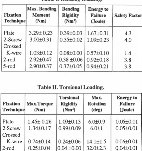
mm saw blade. Five commonly used types of internal fixation were chosen for analysis: dorsal plating with lag screws, two interfragmentary lag screws, crossed K-wire with tension bands, five stacked intramedullary rods, and paired intramedullary rods. Modes of loading included four-point bending, torsion, tension, and compression. Details regarding fixation techniques and the experimental set-up have been described in the earlier workTable I. Bending Loading.
Max. Bending Bending Energy to
Flxatlon Moment Rigidity Failure Safety Factor
Technique (Nm) (NmZ) (Joule)
Plate 3.29± 0.23 0.39±O.03 1.67±O.31
2-Screw 3.00±0.31 0.35±0.02 1.09±O.23
Crossed
K-wire 1.03±0.12 0.08±O.OO 0.57±O.lO
2-rod 2.92±0.47 0.38 ±O.06 0.92±O.l8
5-rod 2.90±0.37 0.37±O.05 0.94±O.21
Table II. Torsional Loading.
Torsional Max. Flxatlon Max.Torque Rigidity Rotation
Technique (Nm) (NmZ) (deg)
Plate 1.45± 0.26 1.09±0.13 6.0±0.9
2-Screw 1.34±O.l7 0.99±O.09 6.0±1
Crossed
K-wire 0.74±0.14 0.24±0.06 14.l±I.5
2-rod 0.25±0.04 O.04 ±O.OO 32.0±2.3
5-rod 2.26±0.04 0.04±0.00 33.7±2.9
Table III. Axial Loading.
Flxation Max.Load Technique (N)
Plate (com) 1097± 130 (ten) 290±30 2·Screw(com) 947±121
(ten) 241±29 Crossed
K-wire (com) 827±81 (ten) 232±26 2-rod (com) 981±93
(ten) -5-rod (com) 989±106
(ten)
-com= compression ten= tension
Axial Energy to
Rigidity Failure (KN) (Joule)
39.8±2.1 1.21±O.30
17.8±1.4 0.25±O.04
37.7±4.4 0.89±O.19 16.5±1.9 0.10±0.02
23.2±2.8 1.18±O.17 1O.6±I.4 0.20±0.02
28.2±4.1 1.40±0.16
-
-28.0±1.0 1.39±O.26
-
-of the authorsl5 and is briefly outlined here.
4.3 4.0 1.4 3.8 3.8 Energy to Failure (Joule) 0.05±O.01 0.05±O.01 0.06±O.01 Q.04±O.OI 0.05±O.01 Safety Facto. 7.7 2.0 6.5 1.7 5.7 1.6 6.7 -6.8
-For each of the plate, 2-screw, and K-wire tension band fixations, 28 samples and for each of the 2-rod and 5-rod fixations, 21 samples were prepared. The ends of each bone were set in acrylic (repair acrylic-Lang Dental Mfg. Co. Inc. Chicago,
IL)
and allowed to cure for one hour beforemechanical testing. All biomechanical tests were performed on an Instron machine. Upon bending, each bone was supported by its acrylic ends in the fixture and loads of equal values were applied at two equidistant points proximal and distal to the osteotomy site in an apex dorsal direction. In axial loading, the acrylic ends of the metacarpals were secured in the crosshead fixtures and loaded in either ,
I
E
�
3
'E 2-Q) E o E OJ c: '6 c: 1
Q)
.0
E :J E ·x III
::2: o.
-,
3
-5-
-2 c--
-5 I---
-
I----
-5-
-plate 2·screw . crossed K·wire 2-rod 5--rod
Different Fixation techniques
Fig. 1. Maximum bending moments of fixation techniques during
testing to failure in an apex dorsal four-point bend. The bold
horizontal line represents the limit of physiological bending
1.
1.
� 1.
E
�
Q) :J
E!
.9 o. C
:J
E 0
. �
::2: 0
moment.
;
�
!
I
--
I-
s-4
I---2
I
-�
-11
plate 2-=ow croaed K_e· 2-rod 5-<od Different Fixation techniques
�
11_
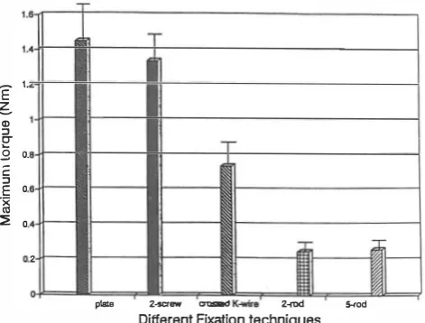
Fig. 2. Maximum torque of fixation techniques during testing tofailure.
compression or tension. In bending and axial loading the crosshead speed of the testing machine was kept constant at 0.5 mm/min. In torsion, one acrylic end of the metacarpal was rigidly fixed and the other end was loaded in torsion at aconstant rate of9 deg/min. The plate, 2-screw, andK-wire tension band fixations were tested in all four modes of loading. The intramedullary rod fixations, however, because of their weakness in tension, were only tested in four-point bending, torsion, and compression.
Maximum load to failure, structural rigidity, and energy absorbed to failure for each ftxation technique and each mode of loading were determined.
An
axial force andbending moment of 145 Newton and
0.76
Newton-meter, respectively, were used as the basis for examining the clinical capabilities of these fixation techniques. Using these values as a guide, the safety factors of different�
1:J III .2 E :J E ·x III ::2:plate 2-screw 2-rod
Different Fixation techniques
Fig. 3. Maximum axial loads of fixation techniques during testing to failure in compression and tension. The horizontal hatched plane represents the limit of physiological axial load.
fixation techniques subjected to physiological loadings were determined. For each of the five fixation techniques seven specimens were tested in each mode ofloading. The average and the standard deviation were determined and appropriate comparisons were made. Significance was determined in unpaired Student's t-test at the P<0.05 level, with use of a statistical graphic system.
An
attempt was made to maintain consistency in variableparameters such as bone density, metacarpal size and geometry, and preparation of osteotom ies wherever possible .
RESULTS
Data on the 4-point bending of different fixation techniques are presented in Table 1. The formula used in calculating bending rigidity was EI= Fa (3U-4a2)/24W, whereL=span between supports, F=forces applied at equal distance to each support, a=distance from each support to the point of application of load, and W =maximum deflection at the fracture site.15 Failure was defined either by a sudden drop of applied load due to fracture of bone (or failure of implant), or a maximum displacement of 3 mm, whichever happened fast. Energy absorbed to failure was derived from the area under the load deformation curve, and safety factors were determined based on the threshold of the appropriate physiological loading. In Fig. 1 the maximum physiological bending moment is depicted by a bold horizontal line for comparison to the bending threshold of each fixation technique.
Torsional test data were analyzed for maximum torque, average torsional rigidity, maximum rotation, and energy to failure. The results are presented in Table II and Fig. 2. The formula used in calculating torsional rigidity was GJ = TL/
compresio
e,
where T= torque measured, L=effective specimen length,
and
e =
angular rotation in radians.
Data on the compression and tension tests are presented
in Table II. The formula used in calculating axial rigidity
was
AE=
FL/<>, whereF=axialloading, L=effective specimen
length and <>
=
axial deformation. In Fig. 3, the maximum
physiological axial loading is depicted by a horizontal plane
for comparison to the axial loading threshold of each fixation
technique.
The intramedullary rods were the weakest form of
fixation in torsion and the K-wire tension band was the
weakest fixation in bending
(P<
0.025). All the fixations
except the intramedullary rods,
in
tension and torsion, could
tolerate the assigned physiological loadings below their
failure limits. Safety factors for K-wire tension band in
bending and compression were 1.4 and 5.7, respectively,
compared to those of dorsal plate fixation (4.3, 7.7) and the
2-screw fixation (4.0,6.5). Torsional rigidity of the K-wire
tension band fixation was significantly less than both plate
and 2-screw fixations (0.24 Nm/deg vs. 1.1 and 1.0 Nm/deg,
respectively).
DISCUSSION
The clinical outcome of various forms of metacarpal
fracture fixation indicates that an optimal result is not
necessarily associated with the strongest construct. If the
physiological loadings on these fixations are in fact less than
the failure loads, the essential amount of maximum rigidity
is debatable. The ideal fixation would require a minimum
amount of materials capable of anatomical fixation with the
least amount of dissection that can withstand physiological
loading. This study was designed to compare the functional
capabilities of different fixation constructs under
physiological loadings in an attempt to identify the optimal
fixation technique rather than the strongest one.
The threshold for physiological torsional loading is not
well dermed in the literature; its maximum value, however,
has been reported to be below that of bending.11,12 Our
results showed that fixation by interfragmentary lag screws
provides a high degree of safety factor in torsional loading.
The K -wire tension band fixation showed a marginal safety
factor of only 1.4 in bending. Its torsional rigidity was
significantly smaller than those of plate and 2-screw fixations.
Despite these findings, K-wire fixation is listed by some
authors as the preferred technique of internal fixation10,l7
which may
bedue, at least
in
part,to the relative ease of
closed reduction and percutaneous fixation.
This study demonstrated that fixation by interfragmentary
lag screws without the application of a dorsal plate provides
stable fixation with minimal surgical trauma and adequate
rigidity exceeding physiological demands without any
implant bulk. This result concurs with the outcome of our
clinical study of 42 patients with a total of
64
metacarpal
shaft fractures treated in our institution.I3
Noting that the assigned physiological loads in this
study are rarely approached
in vivoand that the soft tissue
supports may add strength to the fixations, promotes our
conclusion that the dorsal plate fixation, although the
strongest, may not clinically
bethe optimal fixation.
ACKNOWLEDGEMENT
This study was aided by a grant from the Orthopedic
Research and Education Foundation (OREF), USA.
REFERENCES
1. Stern PS, Wieser MS, Reilly DG: Complications of plate
fixation in the hand skeleton. Clin Orthop 214: 59-65, 1987.
2. Woo SLY, Akeson WH, Coutts RD, Rutherford L, Doty D, Jemmott GF, Arniel D: A comparison of cortical bone atrophy secondary to fixation with plate with large differences in bending stiffness. J Bone Joint Surg 58A: 190, 1976. 3. Black DM, Mann RJ, Constine R, Daniels AU: Comparison of
internal fixation techniques in metacarpal fractures. J Hand Surg lOA: 466-72, 1985.
4. Black DM, Mann RJ, Constine RM, Daniels AU: The stability of internal fixation in the proximal phalanx. J Hand Surg l1A: 672-7, 1986.
5. Fyfe IS, Mason SM: The mechanical stability of internal fixation of fractured phalanges. Hand 11: 50-4, 1979. 6. Mason SM, Fyfe IS: Comparison of rigidity of whole tubular
bones. J Biomech 12: 367-72,1979.
7. MassengilIJB, Alexander H, LangranaN, Mylod A: A phalangeal fracture model quantitative analysis of rigidity and failure. J Hand Surg 7: 264-79, 1982.
8. Nunley JA, Kloen P: Biomechanical and functional testing of plate fixation devices for proximal phalangeal fractures. J Hand Surg 16A: 991-8, 1991.
9. Yanik RK, Weber RC, Matloub HS, Sander JR, Gingrass RP: The comparative strengths of internal fixation techniques. J Hand Surg 9A: 216-21, 1984.
10. Viegas SV, Ferren LF, Self J, Tencer AF: Comparative mechanical properties of various Kirschner wire configurations in transverse and oblique phalangeal fractures. J Hand Surg 13A: 246-53, 1988.
11. Nordyke MD, Lewis RC, Janssen HF, Duncan KH:
Biomechanical and clinical evaluation of the expandable intramedullary fixation device. J Hand Surg 13A: 128-34. 1988.
12. Paavolainen P, Karaharju E, Slatis P, Ahonen J, Holmstrom T: Effect of rigid plate fixation on the structure and mineral content of cortical bone. Clin Orthop 136: 287, 1978.
13. Shantharam SS,MoneimMS, OmerGE, Vichick DA: Abstract, Orthopaedic Transactions 16: 3, 718, 1992-93.
14. Dabezies EJ, Schutte JP: Fixation of metacarpal and phalangeal fractures with miniature plates and screws. J Hand Surg 11A:
283-8, 1986.
15. Firoozbakhsh K, Moneim MS, Howey T, Castaneda E, Pirela Cruz MA: Comparative fatigue strengths and stabilities of metacarpal internal fixation techniques. J Hand Surg 18 A(5): 1059-68, 1993.
16. Mann RD, Black D, Constine R, Daniels AU: A quantitative comparison of metacarpal fracture stability with five different methodsof internalfixation.J Hand Surg lOA: 1024-28, 1985. 17. Belsky MR, Eaton RG, Lane LB: Closed reduction and internal fixation of proximal phalangeal fractures. J Hand Surg 9A: 725-9, 1984.
18. Lister G: Intraosseous wiring of the digital skeleton. J Hand Surg 3: 427-35, 1978.
19. Greene TL, Noellert RC, Belsole PJ, Simpson LA: Composite wiring of metacarpal and phalangeal fractures. J Hand Surg 14A: 665-9, 1989.
20. Geldmacher J: Das Kline fragment im finger und mittelhandkereich. Handchir 12: 83-4, 1980.
21. Hidaka S, Gustilo RB: Refracture of bones of the forearm after plate removal. J Bone Join1 Surg 66A: 1241, 1984.
22. Alexander H, Langrana N, Massengill JB, Weiss AB: Development of new methods for phalangeal fracture fixation. J Biomech 14: 377-87, 1981.
23. An KN, Chao EY, Cooney WP, Linscheid RL: Normative
model of human hand for biomechanical analysis. J Biomech 12:775,1979.
24. An KN, Chao EY, Cooney WP, Linscheid RL: Forces in the normal and abnormal hands. J Orthop Res 3: 202,1985. 25. An KN, Chao EY, Cooney WP, Linscheid RL: Determination
of forces in extensor pollicis longus and flexor pollicis longus of the thumb. J Appl Physiol 54 A: 714, 1983.
26.Berme N, Paul JP, Purvis WK: A biomechanical analysis of the metacarpophalangeal joint. J Biomech 10: 409-412, 1977.
27. Chao EY, Opgrande JD, Axmear FE: Three dimensional force analysis of finger joints in selected isometric hand functions. J Biomech 9: 387, 1976.
28. Cooney WP, Chao EY: Biomechanical analysis of static forces in the thumb during hand function. J Bone Joint Surg 59 A: 27, 1977.
29. Toft R, BermeN: A biomechanical analysis of the joints of the thumb. J Biomech 13: 353-360, 1980.
30. Ketchum LD, Brand PW, Thompson D, Pocock GS: The determination of moments for extension of the wrist generated by muscles of the forearm. J Hand Surg 3: 205-10, 1978.
31. Ketchum LD, Thompson D, Pocock GS, Wallingford D: A clinical study of forces generated by the intrinsic muscles of the index finger and the extrinsic flexor and extensor muscles of the hand. J Hand Surg 3: 571-8, 1978.