ScholarWorks@UNO
ScholarWorks@UNO
University of New Orleans Theses and
Dissertations Dissertations and Theses
Fall 12-16-2016
Fault Discrimination Algorithm for Busbar Differential Protection
Fault Discrimination Algorithm for Busbar Differential Protection
Relaying Using Partial Operating Current Characteristics
Relaying Using Partial Operating Current Characteristics
Monir Hossain
University of New Orleans, [email protected]
Follow this and additional works at: https://scholarworks.uno.edu/td
Part of the Power and Energy Commons
Recommended Citation Recommended Citation
Hossain, Monir, "Fault Discrimination Algorithm for Busbar Differential Protection Relaying Using Partial Operating Current Characteristics" (2016). University of New Orleans Theses and Dissertations. 2263.
https://scholarworks.uno.edu/td/2263
This Thesis is protected by copyright and/or related rights. It has been brought to you by ScholarWorks@UNO with permission from the rights-holder(s). You are free to use this Thesis in any way that is permitted by the copyright and related rights legislation that applies to your use. For other uses you need to obtain permission from the rights-holder(s) directly, unless additional rights are indicated by a Creative Commons license in the record and/or on the work itself.
Fault Discrimination Algorithm for Busbar Differential
Protection Relaying Using Partial Operating Current Characteristics
A Thesis
Submitted to Graduate Faculty of the University of New Orleans in partial fulfillment of the requirements for the degree of
Master of Science in
Engineering Electrical Engineering
By Monir Hossain University of New Orleans
Acknowledgement
First of all, I would like to express my utmost gratitude to my academic and research
advisor Dr. Parviz Rastgoufard for his guidance and constant support to conduct and accomplish
this thesis. I would also like to express deepest appreciation to the members of the supervisory
committee, Dr. Ittiphong Leevongwat and Dr. Ebrahim Amiri for their enormous support
throughout my masters program to complete this work.
Finally, I like to wish acknowledge and thank to my parents, my wife and all of my
Table of Contents
List of Figures v
List of Table viii
Abstract ix
1 Introduction 1
1.1 Overview of Power System 1
1.2 Overview of Power System Protection 2
1.3 Overview of Busbar Protection 5
1.4 Low Impedance Differential Protection: CT Saturation Issues 10
1.5 Literature Review of Low Impedance Differential Protection 11
1.6 Current Transformer (CT) Saturation 16
1.7 Literature Review of CT Saturation Detection 18
1.8 Scope of Thesis 20
2 Mathematical Modeling 22
2.1 Differential Protection Principle 22
2.1.1 Basic of Differential Protection 22
2.1.2 Restrained Differential Protection 26
2.2 Mathematical Modeling of CT Saturation 28
2.3 Existing Methods to Discriminate Internal and External Faults 35
2.3.1 Phase Angle Comparison Method 35
2.3.2 Differential Rate of Change Method 37
3 Thesis Contribution 39
3.1 Problem Statement: Difficulties to Discriminate Faults 39
3.2 Objective 40
3.3 Mathematical Model of Partial Operating Current and Proposed Algorithm 40
3.3.1 Mathematical Model of Partial Operating Current 41
3.3.2 Proposed Algorithm 48
3.4 Relay Design 50
3.4.2 CT Saturation Detection Algorithm 51
3.4.3 Trip Logic Unit 53
4 Test System 55
4.1 Description of the Test System 55
4.2 Transmission Line Data 55
4.3 Generator Data 56
4.4 Load Data 57
5 Simulation and Results 58
5.1 System Modeling at EMTP 58
5.2 Relay Modeling at Matlab 61
5.3 Bus Faults 62
5.4 Results and Discussion 64
6 Concluding Remarks and Future Research 90
Bibliography 93
Vita 97
List of Figures
Figure 2.1 Electrical node or junction 23
Figure 2.2 Two terminal zone under normal condition 24
Figure 2.3 Two terminal zone under fault condition 24
Figure 2.4 Multi terminal zone under normal condition 25
Figure 2.5 Multi terminal zone under fault condition 25
Figure 2.6 Characteristics curve of double slope restrained differential relay 27
Figure 2.7 CT circuit model 28
Figure 2.8 CT excitation curve 29
Figure 2.9 Method of determining the parameters Vsand S 29
Figure 2.10 Postulated instantaneous values saturation curve 30
Figure 2.11 Comparison of the rms/peak relationship for two wave shapes 32
Figure 2.12 Definition of per unit remanence 34
Figure 2.13 External Fault scenario 36
Figure 2.14 Internal Fault scenario 36
Figure 2.15 Trajectory of 𝐼𝑜𝑝 and 𝐼𝑟 37
Figure 2.16 Logic Diagram of Differential Rate of Change Method 38
Figure 3.1 Single phase representation of a typical multi terminal protection zone 41
Figure 3.2 Normal operating condition 42
Figure 3.3 Phasor diagram in normal operational condition 43
Figure 3.4 Internal fault condition 44
Figure 3.5 Phasor diagram during internal fault condition 45
Figure 3.6 External fault condition 46
Figure 3.7 Phasor diagram during external fault condition without CT saturation 46
Figure 3.8 Phasor diagram during external fault condition with CT saturation 47
Figure 3.9 Flow chart of proposed algorithm 49
Figure 3.10 Block diagram of proposed relay 50
Figure 3.11 CT saturation detection algorithm 52
Figure 3.13 Trajectory of operating and restrained current 53
Figure 3.14 Trip logic diagram 54
Figure 4.1 Three bus test system 55
Figure 5.1 EMTP model of three bus test system 59
Figure 5.2 EMTP current transformer (CT) model 60
Figure 5.3 CT secondary currents for LG internal fault 65
Figure 5.4 Responses from proposed method for LG internal fault 65
Figure 5.5 Comparative results for LG internal fault 66
Figure 5.6 CT secondary currents for LL internal fault 67
Figure 5.7 Responses from proposed method for LL internal fault 67
Figure 5.8 Comparative results for LL internal fault 68
Figure 5.9 CT secondary currents for LLG internal fault 69
Figure 5.10 Responses from proposed method for LLG internal fault 69
Figure 5.11 Comparative results for LLG internal fault 70
Figure 5.12 CT secondary currents for LLL internal fault 71
Figure 5.13 Responses from proposed method for LLL internal fault 71
Figure 5.14 Comparative results for LLL internal fault 72
Figure 5.15 CT secondary currents for LLLG internal fault 73
Figure 5.16 Responses from proposed method for LLLG internal fault 73
Figure 5.17 Comparative results for LLLG internal fault 74
Figure 5.18 CT secondary currents for LG high impedance internal fault 75
Figure 5.19 Responses from proposed method for LG high impedance internal fault 76
Figure 5.20 Comparative results for LG high impedance internal fault 76
Figure 5.21 CT secondary currents for LL high impedance internal fault 77
Figure 5.22 Responses from proposed method for LL high impedance internal fault 78
Figure 5.23 Comparative results for LL high impedance internal fault 78
Figure 5.24 CT secondary currents for LG external fault 80
Figure 5.25 Responses from proposed method for LG external fault 80
Figure 5.27 CT secondary currents for LL internal fault 82
Figure 5.28 Responses from proposed method for LL internal fault 82
Figure 5.29 Comparative results for LLG internal fault 83
Figure 5.30 CT secondary currents for LLG internal fault 84
Figure 5.31 Responses from proposed method for LLG internal fault 84
Figure 5.32 Comparative results for LLG internal fault 85
Figure 5.33 CT secondary currents for LLL internal fault 86
Figure 5.34 Responses from proposed method for LLL internal fault 86
Figure 5.35 Comparative results for LLL internal fault 87
Figure 5.36 CT secondary currents for LL internal fault 88
Figure 5.37 Responses from proposed method for LL internal fault 88
List of Tables
Table 3.1 The truth table for trip logic 53
Table 4.1 Transmission line data 56
Table 4.2 Transmission line tower configuration 56
Table 4.3 Generator data 57
Table 4.4 Load data 57
Table 5.1 CT parameters 60
Table 5.2 CT Ψ-I characteristic 61
Table 5.3 Settings for proposed relay 62
Table 5.4 List of bus faults 63
Abstract
Differential protection is the unit protection system which is applied to protect a
particular unit of power systems. Unit is known as zone in protection terminology which is
equivalent to simple electrical node. In recent time, low impedance current differential
protection schemes based on percentage restrained characteristics are widely used in power
systems to protect busbar systems. The main application issue of these schemes is mis-operation
due to current transformer (CT) saturation during close-in external faults. Researchers have
suggested various solution of this problem; however, individually they are not sufficient to
puzzle out all mis-operational scenarios. This thesis presents a new bus differential algorithm
by defining alternative partial operating current characteristics of a differential protection zone
and investigating its performance for all practical bus faults. Mathematical model of partial
operating current and operating principle of the proposed bus differential relay are described in
details. A CT saturation detection algorithm which includes fast and late CT saturation
detection techniques is incorporated in relay design to increase the sensitivity of partial
operating current based internal-external fault discriminator for high impedance internal faults.
Performance of the proposed relay is validated by an extensive test considering all possible
fault scenarios.
Keywords: Differential Protection; CT Saturation; Internal Fault; External Fault; Fault
Chapter 1
1. Introduction
In Chapter 1 we provide a general idea about a power system and its protection,
especially the bus protection. Various differential protection schemes are used in modern
power systems. Particularly, for bus protection, low impedance differential protection is very
popular and effective [1]. However, current transformer (CT) saturation has a severe impact on
the performance of low impedance differential protection. The overview of current transformer
(CT) saturation and historical review of low impedance bus differential protection as well as
current transformer (CT) saturation are presented. After extensive historical review of existing
methods, the outline of this thesis is provided in Section 1.8.
1.1 Overview of Power System
Modern power systems are the combination of various complex elements such as
generators, transformers, transmission lines, loads and protection and control equipments.
Generally, power systems are divided into three stages: generation, transmission and
distribution. The most convenient method to generate electricity is to burn fossil fuels to
convert water into steam which is used to rotate a turbine that is connected to the rotor shaft
of an electric generator. Water is also used to turn generators in hydro-electric power plant. In
the last few decades, various new sources of electricity has been introduced which is called
renewable energy such as solar, wind, geothermal and biomass etc. In all cases, the electricity
generated at these facilities flows across the transmission system. Voltage at the generating
to transmit power over long distance to reduce the higher voltage level transmission loss by
reducing current. At the end of transmission system, voltage is stepped down by using step
down transformer for power flow through distribution system and for supplying to residential
and commercial customers.
The primary goal of any electric power utility is to provide uninterrupted power to the
end consumer, and to achieve the goal, electric utilities depend on protection systems to
provide protection to power systems equipment and elements such as generators,
transformers, bus bars, overhead transmission lines operating in abnormal or fault conditions.
Most important criteria of power systems are the balance between generation and
demand and to maintain the balance, utilities all over the world use various control systems
such as supervisory control and data acquisition (SCADA) system and automatic generation
control (AGC) system.
1.2 Overview of Power System Protection
The main purpose of a power system protection is to isolate a faulty section of the
electrical power system from rest of the healthy systems so that the remaining live portion can
function satisfactorily without any severe damage due to fault current [1]. Identification fault
and isolating faulty part from the remaining healthy systems to secure the continuation of
power supply are not straightforward.
The elementary power system protective device is the fuse. When the current through a
fuse exceeds a certain threshold, the fuse element melts and produces an arc across the
resulting gap that is then extinguished to interrupt the circuit [2]. Given that fuses can be built
however have two problems: first, after they have functioned, fuses must be replaced as they
cannot be reset. This can prove inconvenient if the fuse is at a remote site or a spare fuse is not
on hand. And second, fuses are typically inadequate as the protective device in most power
systems as they allow current flows well in excess of that that would prove lethal to a human or
animal. In general, fuses are used to protect simple and low power equipments. They are not
suitable to use as the sole safety device in modern day high voltage and complex power
systems.
Modern day’s power system protection schemes are very sophisticated. They are built
by integrating various complex devices or components. Circuit breaker, relay and DC system are
the three main components of any protection scheme of power systems. All of these three
components of protection scheme work simultaneously to give effective security against faults.
Circuit breaker isolates the faulty system from rest of the healthy system and this circuit
breakers automatically open during fault condition due to its trip signal comes from protection
relays [1].
Depending on arc quenching mechanisms, circuit breakers are classified as bulk oil
circuit breaker, minimum oil circuit breaker, SF6 circuit breaker, air blast circuit breaker and
vacuum circuit breaker etc. They are also classified as solenoid circuit breaker, spring circuit
breaker, pneumatic circuit breaker, hydraulic circuit breaker etc. depending on operating
mechanisms.
Power system protection relays are classified as current relays, voltage relays,
operating characteristics, they are categorized as definite time relays, inverse time relays,
stepped relays etc. According to operating logic, they are categorized as over current relays,
distance relay and differential relays etc.
All the circuit breakers of electrical power systems are DC (Direct Current) operated.
Because DC power can be stored in battery and if situation comes when total failure of AC
power occurs, still the circuit breakers can be operated for restoring the situation by the power
of storage battery . Hence the battery is another essential item of the power system protection.
Some time it is referred as the heart of the electrical substation. An electrical substation battery
or simply a station battery containing a number of cells accumulate energy during the period of
availability of AC supply and discharge at the time when relays operate so that relevant circuit
breaker is tripped.
The main philosophy of protection is that no protection of power systems can prevent
the flow of fault current through the system, it only can prevent the continuation of flowing of
fault current by quickly disconnect the short circuit path from the system [1] [3]. Protection
systems should have several important functional requirements to satisfy this quick
disconnection.
Reliability is the most important requisite of power system protection. The protection
relays should remain inoperative for a long time before a fault occurs; but if a fault occurs, they
must respond instantly and correctly.
Selectivity is another important requisite of power system protection schemes. Relays
system. There may be some typical condition during fault for which some relays should not be
operated or operated after some definite time delay and so protection relays must be
proficient to select appropriate condition for which it would be operated.
The protective relays must be sufficiently sensitive so that it can be operated reliably
when level of fault condition just crosses the predefined set limit.
Another important requisite of protection systems is the speed of operation. The
protective schemes must operate within set time duration after detecting fault. There must be a correct coordination provided in various power system protection relays in such a way that
for the fault at one portion of the system should not disturb other healthy portions [4] [5]. Fault
current may flow through a part of healthy portion as they are electrically connected. However,
relays associated with that healthy portion should not be operated faster than the relays of
faulty portion otherwise undesired interruption of healthy systems may occur. If relay
associated with faulty portion is not operated in proper time due to any defect in it, then only
the next relay associated with the healthy portion of the system must be operated to isolate
the fault [4] [5]. Therefore, it should neither be too slow which may result in damage to the
equipment nor should it be too fast which may result in undesired operation.
1.3 Overview of Busbar Protection
The main objectives of all protection schemes, specifically to maintain continuity of
supply and limit the material damage, are achieved by isolating the faulty element as quickly as
possible. Delay increases not only the risk of damage of faulty element and it’s adjacent
by, for example, loss of stability and reduction of voltage. Hence, no part of power systems can
safely be left unprotected, much less the busbars because of their especially vital position and
function in the system. All means of protection, even those applied to the earliest and simplest
system, have in some way or other contrived to satisfy the precept that all elements of the
system must be protected, including busbars [6]. Busbar is the most critical element of a power
system, as it is the point of convergence of many transmission lines, transformers, generators
and loads. The effect of a single bus fault is equivalent to many simultaneous faults and usually,
due to the concentration of supply circuits, involves high current magnitudes. Any incorrect
operation would cause the loss of all of these elements. Therefore, protection of busbar
demands high speed, reliability and stability. Failure-to-trip on an internal fault, as well as false
tripping of a busbar during service, or in case of an external fault, can both have disastrous
effect on the stability of the power system, and may even cause complete blackout of the
system [7]. So, it is very essential to incorporate precision and reliability factors during
designing a busbar protection scheme. It was a very old practice in small substations to provide
over-current relays to work for the protection of the busbar and no separate relays were used
for the purpose as this was not found to be cost effective. But, with the increase in substation
equipments and feeder’s complexity, it was felt necessary to go for reliable busbar protection
schemes. The methods most commonly used to protect busbars are frame leakage protection,
direction comparison protection and differential protection.
The frame leakage method involves insulating the bus-supporting structure and its
switch gear from ground; and interconnecting all the framework, circuit-breaker tanks, etc. to
of that CT is connected with an over current relay. The over current relay drives a
multi-contact auxiliary relay that trips the breakers of all circuits connected to the bus. This method
is most effective when the switchgear is of the isolated-phase construction. However, it is
possible to design other types of switchgear with special provisions for making ground faults
the most probable. If phase to phase faults not involving ground occur, the frame leakage
method would probably not be justified. The frame leakage protection is quite popular in
small indoor installations [8]. This method is most effective for the metal-clad type installation
where provision can be made for effective insulation from ground. Certain existing
installation may not be adaptable to fault-bus protection, owing to the possibility of other
paths for short-circuit current to flow to ground. It is necessary to insulate cable sheaths
from the switchgear enclosure and entrance bushing support from the rest of the structure
otherwise cable ground-fault currents may find their way to ground through the fault-bus CT and
improperly trip all the switchgear breakers. For sectionalized bus structure, separate frame
leakage relaying must be employed for each section. The frame leakage method does not
offer overlapping of protective zones; therefore complementary relaying is required to
protect the regions between bus sections.
The directional comparison method is based on the comparison of relative directions
of the fault currents flow in all the circuits connected to the busbar. For bus faults, currents
through all circuits connected to the bus flow toward bus; however, fault current flows
outward from the busbar in at least one circuit for external fault [6]. Typically, this principle
has been used only with ground relays, on the basis that most bus faults start as ground faults, or
Phase relays can also be used; however, it is more costly than other bus protection systems.
The chief disadvantage of this scheme is the greater maintenance required and the
greater probability of failure to operate because of the large number of contacts in series in
the trip circuit [3]. Another disadvantage is that connections from the current
transformers in all the circuits must be run all the way to the relay panel if phase relays were
used. Moreover, phase would depend on bus voltage for polarization, and, therefore, they
might not operate for a metallic short circuit that reduced the voltage practically to zero.
Differential protection is widely used to protect busbar because of its versatility and cost
effectiveness. Differential relays are very sensitive to the faults occurred within the protected
zone but they are least sensitive to the faults that occur outside the protected zone. The
operating principle of differential relay is somewhat different from other relay. The differential
relay operates when there is a difference between two or more similar electrical quantities
exceeds a set or threshold value. In differential relaying scheme, more than one current come
from different parts of an electrical node or junction. Summation of these currents passes
through the relay coil. According to Kirchhoff Law, the phasor sum of these currents is zero at
normal operating condition [9]. Therefore, no current will be flowing through the relay coil at
normal operating conditions. But due to any abnormality in the node or junction, the phasor
sum of these currents no longer remains zero and this non-zero current will be flowing through
the relay coil therefore relay being operated. In differential scheme, more than one set of
current transformer are involved to protect equipment by differential relay. The ratio of the
current transformer (CT) needs be chosen carefully. The polarity of CTs is another very
inside the protected zone or equipment in other words differential relay should clear only
internal fault of the zone or equipment [10]. Therefore, the protected zone or equipment
should be isolated as soon as any fault occurred inside the equipment or zone. They need not
be waiting or delaying for coordination with other relays in the system. There are mainly two
types of differential protection system depending upon the principle of operation: voltage
balanced differential protection and current balanced differential protection.
In voltage balanced differential protection scheme, the current transformers are
connected in such a way that EMF induced in the secondary of current transformers (CTs) will
oppose each other according to the original current direction at primary circuit. The differential
relay coil is connected in the loop created by series connection of secondary of CTs. In normal
operating conditions and also in through fault conditions, resultant EMF is zero and hence no
current would be flowing through the relay coil. But as soon as any internal fault occurs in the
protected zone, the resultant EMF is no longer balanced hence current starts flowing through
the relay coil and finally trips circuit breakers [3]. Multi tap transformer construction is required
to accurate balance between current transformers.
In current balanced differential scheme, current transformers (CTs) are connected in
such a way that the secondary currents of CTs will oppose each other according to the original
current direction at primary circuit. Summation of these currents which is called operating
current which passes through the operating coil of the relay element. Ideally, under normal
operating conditions or external through fault conditions, current summation is zero; hence no
protected zone, summation of secondary currents will be no longer zero. In this situation the
differential relay is being operated to isolate the faulty zone from the system [11] [12].
According to the type of relay used, there are two kinds of current balanced differential
protection such as high impedance and low impedance differential protection.
In high impedance differential protection, relay is connected with a high impedance
resistance. Here, voltage relay is used that means relay is operated by voltage [3]. Any
operating current is forced through the high impedance causing voltage drop across the relay
and relay gets trip.
In low impedance differential protection, a relay operated by current is used and it has
low impedance current inputs. If any operating current resulting from an internal fault passes
through the operating coil of the relay and relay gets trip.
1.4 Low Impedance Differential Protection: CT Saturation Issues
Recently, micro-processor based low impedance differential protection schemes have
become popular to protect busbars. Low impedance differential protection schemes are
operated based on operating current which is the summation of all CT secondary currents.
Practically summation of the secondary current is not zero even for normal operating
conditions as accurate matching of characteristics of current transformer cannot be achieved
hence there may be spill current flowing through the relay in normal operating conditions.
Moreover, there may be a probability of mismatching in cable impedance from CT secondary to
the remote relay panel. These uneven pilot cables’ capacitance causes high current through the
as false operating current and it becomes high during high loading conditions or high system
congestion. To overcome these issues, the concept of restrained current has been adapted with
low impedance differential scheme. This modified scheme is known as percentage restrained
differential protection because the operating current required to trip can be expressed as a
percentage of restrained current. There are several mathematical definitions of restrained
current. In most of the cases, the restrained current is defined by half of the summation of
secondary currents magnitude of all CTs involved with protected zone [13]. Under normal and
through fault conditions, operating current is less than a percentage of restraining current
therefore relay remains inactive. During internal fault, the operating current becomes greater
than a percentage of restrained current and the relay is operated [14].
The main application issue with this modified differential protection is to make it secure
from mal-operation in response to the CT saturation during close-in external faults. During
close-in external faults, probability of CT saturation becomes high and this CT saturation creates
high operating current in CT secondary circuit which causes the undesired operation of relay.
The primary reason for such mal-operation is the fact that the traditional percentage
differential principle relies exclusively on current magnitude rather than directionality for
tripping decisions. Therefore, proper discrimination of external and internal fault becomes the
main concern for the performance of bus bar differential protection.
1.5 Literature Review Low Impedance Differential Protection
To prevent the mal-operation of current balanced busbar differential protection due to
current transformer saturation especially during external fault, several techniques were
discrimination techniques to secure current balanced bus bar differential protection system
from false operation.
Multi slope Percentage restrained differential protection is one of the oldest forms of
adaptive protection algorithms. The slope characteristic can provide high sensitivity when low
levels of current are flowing in the zone of protection but has less sensitivity when high levels of
current are flowing [14]. This improves security because CTs are more prone to saturation when
they have to reproduce high levels of current in the primary circuits. Although the above slope
characteristic provides some security against CT errors, it is not adequate for all practical
scenarios. Two common failures reported with conventional slope characteristics are due to CT
saturation which occurs during close-in external faults and the subsidence currents present
after clearing external faults.
Several techniques were proposed based on CT saturation detection supervision to
prevent mal operation of bus differential relay during CT saturation in external fault. However,
they are failed to provide complete solution as CT can also be saturated during internal fault. A
harmonic-current-based restraining method was introduced by Kennedy and Hayward [15]. If
the harmonics contained in the differential current are larger than the threshold, the relay is
inhibited. The method ensures stability on an external fault, but delays the operating time of a
relay for an internal fault until after the DC component decays to a low value. When a CT
saturates, the operating time is significantly increased. An algorithm that detects the onset of
CT saturation based on the first-difference function of the current was described by Phadke and
Difficulties arise if the current does not collapse to a low value during saturation. A solid-state
busbar protection relay was proposed by Royle and Hill [17]. The relay detects the onset of
saturation by detecting when the current collapses to a low value. It then shunts the current
away from the operating circuit by closing a switch adjacent to the saturated CT. Although this
technique prevents an external fault, the relay causes an operating time delay when a CT
saturates on an internal fault. A microprocessor-based busbar protection relay that included a
countermeasure for CT saturation was reported by Andow et al. [18]. The waveform
discriminating element (WDE) is based on the assumption that the differential current during
an external fault is nearly zero between the periods that corresponds to CT saturation. The
WDE detects the onset of saturation by comparing the change in the instantaneous differential
current against the instantaneous restraining current. The relay is inhibited for a predetermined
period if the former is significantly less than the latter. The WDE is unable to indicate which CT
is saturated and the blocking scheme may delay the operation of the relay on an internal fault.
In addition, for a power system with a large primary time constant, a larger blocking period is
needed and consequently a longer operating time delay is inevitable.
An impedance-based CT saturation detection algorithm for busbar differential
protection was described by Fernandez [19]. The detection algorithm relies on the assumption
that the current is decreased during saturation and thus the impedance is increased. The
impedance is calculated at the relaying point and compared with the source impedance. If the
estimated impedance is larger than the source impedance, saturation is detected and a
blocking signal is issued. The algorithm is only valid if, after fault occurrence, the change in the
impedance increases significantly after fault occurrence. In addition, the algorithm uses a
voltage signal to detect saturation and thus can cause an increase in the operating time. A
microprocessor-based bus bar protection system that estimates the impedances of the
positive- and negative sequence circuits for every feeder connected to the busbar was
proposed by Gill et al. [20]. The basic idea of the algorithm is similar to phase angle comparison.
It compares the direction of current flow for each feeder and consequently is less dependent on
the effect of CT saturation than a magnitude comparison algorithm [21]. The technique detects
an internal fault if all the impedances seen by every feeder are located in the third quadrant of
the impedance plane. The performance of the technique is satisfactory for mild saturation.
However, correct operation of the technique is not guaranteed for severe saturation caused by
a high level of remnant flux. Moreover, the technique requires significant computational
burden as compared with phase angle comparison, since it calculates the positive- and negative
sequence components of the voltages and currents for every feeder. Yong-Cheol Kang et al.,
has proposed a bus differential relay which operates in conjunction with a saturation detection
algorithm based on the third-difference function applied to the current signal [22]
A wavelet transform (WT) based busbar protection scheme that utilizes detail
decomposition of differential current to detect internal faults [23]. The algorithm relies on the
assumption of time shift in transients between differential current and source current as most
of the connected elements are inductive. However, the transients associated with the source
current and the fault current are independent of location of fault (internal or external) which
leads to mal-operation of the protection scheme. A backup protection is proposed based on
mal-operation; even then, this technique is vulnerable at CT saturation and high impedance internal
fault.
The preservation of current phase angle always takes place even if CT saturation or dc
offset conditions occur to the input ac currents. As a result, if the phase angle of the current
waveforms is compared with the phase angle of each of the input bus currents, a decision can
be made whether a fault is external or internal to the differential protected zone irrespective of
the waveform distortions due to the errors in CTs. Comparing phase currents in near real time,
a comparison can be made between currents that are entering the bus and those currents that
are leaving the bus. This is intuitively true since Kirchoff’s law also applies to phase angles as
well as to current magnitudes. However, the key challenge in this method is estimation of
phase angles between all current phase angles rapidly in real time. A technique based on dot
product was used in reference [13] [24] to determine the differences in phase angles. This
technique is suitable for transformer differential protection where two input currents are
involved. But it is critical to implement for bus bar differential protection as more than two
input currents are involved. Moreover, during a high impedance internal bus fault, load flow
may continue to flow on passive elements and may cause the phase angles function to block
the relay from tripping for the internal fault.
A fault discrimination method was proposed based on differential rate of change of
operating current and restrained current [24] [25]. The detection algorithm relies on the
assumption that for an internal bus fault, the rate of change of operating current is greater than
restrained current is greater than the rate of change of operating current. This technique
provides security for low CT saturation during external fault. However, it has limitation for
severe CT saturation as change of operating current becomes high as soon as CT starts
saturated.
A different technique has been proposed based on alienation concept in order to
determine busbar fault type whether internal or external to make relay trip or no trip decision,
respectively [26]. The variance between any two signals is defined as the alienation coefficient,
which is obtained from correlation coefficient. For internal fault, alienation coefficient is greater
than zero and for external fault it is less than zero. In case of CT saturation, this technique
compares the alienation coefficients of unsaturated portion and saturated portion of current to
discriminate the fault. It assumes current remains unsaturated in first quarter cycle. This
technique provides security for slow CT saturation during external fault. However, it leads
mal-operation for severe CT saturation as CT starts saturated in first quarter cycle.
1.6 Current Transformer (CT) Saturation
Protective relays are actuated by current and voltage supplied by current and voltage
transformers. These transformers provide insulation against the high voltage of the power
circuit and also supply the relays with quantities proportional to those of the power circuit,
but sufficiently reduced in magnitude so that the relays can be made relatively small and
cost effective. All types of current transformers are used for protective-relaying purposes. The
bushing CT is almost invariably chosen for relaying in the higher-voltage circuits because it is
equipment [3]. All CT accuracy considerations require knowledge of the CT burden. The
external load applied to the secondary of a current transformer is called the burden. The
burden is expressed preferably in terms of the impedance of the load and its resistance and
reactance components. The term burden is applied not only to the total external load
connected to the terminals of a current transformer but also to elements of that load.
Protective relay accuracy and performance are directly related to the steady state and
transient performance of the CTs. Protective relays are designed to operate in a shorter time
than the time period of the transient disturbance during a system fault. Large errors of CT
transient may delay or prevent relay operation. CT output is impacted drastically when the CT
operates in the nonlinear region of its excitation characteristic [27]. Operation in this region is
initiated by:
o Large asymmetrical primary fault currents with a decaying dc component.
o Residual magnetism left in the core from an earlier asymmetrical fault, or field
testing, if the CT has not been demagnetized properly.
o Large connected burden combined with high magnitudes of primary fault
currents.
The instantaneous CT secondary current is the sum of the instantaneous burden current
and the magnetizing current. The CT steady-state magnetizing current is very negligible as long
as the CT operates in its linear region; therefore the burden current is a replica of the primary
current adjusted by the CT ratio. When the CT is forced to operate in its nonlinear region, the
magnetizing inductance value. The magnetizing current which can be considered as an error
current, subtracts from burden current and drastically affects the current seen by the
connected burden on the CT secondary winding. When the CT saturates because of the dc
component, it can do so in the first few cycles of the fault. Long dc time constant offset faults
can cause CTs to saturate many cycles after a fault [28].
1.7 Literature Review of CT Saturation Detection
Low impedance differential protection is severely affected by the current transformer
saturation during close-in external faults. This CT saturation creates high operating current in
CT secondary circuit which causes the undesired operation of relay. Proper CT saturation
detection is one of the major concerns to prevent mal-operation of bus bar differential
protection.
A CT saturation algorithm has been proposed based on waveform model by A.G. Phadke
and J. S. Throp [16]. It is based on the fact that secondary current is abruptly changed when CT
saturation sets in. However, this algorithm fails when CT secondary current changes slowly.
Another waveform method based on long data window has been proposed to detect CT
saturation [29]. Computational time is comparatively high for this method because number of
involved variables is more. Therefore, this method is slow to use together with any fast tripping
algorithm. An algorithm based on the core flux calculating from a secondary current and then
compensating the distorted secondary current was proposed [30]. The algorithm can
successfully calculate the core flux and detect CT saturation in various conditions. However, this
method is based on the assumption that the remanent (residual) flux at the beginning of
Based on evaluating mean of error and the mean and variance of current amplitude, a
CT saturation detection method was suggested [31]. The error is calculated on the assumption
that the current is a perfect sinusoid. Hence the summation of the current and its second-order
derivative should be zero. C. Fernandez has proposed an impedance-based CT saturation
detection algorithm for bus-bar differential protection [19]. It is based on the first-order
differential equation for the power system source impedance at the relay position and uses the
busbar voltage as well as current signal to detect CT saturation.
An algorithm based on the third difference of a secondary current has been presented
to CT saturation detection [32]. Third difference is more effective to detect CT saturation
because it has large value than first and second difference. However, an anti-aliasing low-pass
filter softens the current and, thus, reduces the values of the third difference at those instants.
Selection of sampling rate is very important to overcome the effect of a remanent (a term used
by IEEE) flux in the core and a low-pass filter on the proposed algorithm.
A method based on symmetrical component analysis has been suggested to detect
current transformer (CT) saturation [33].The proposed algorithm computes the
positive-sequence negative-positive-sequence and zero-positive-sequence components of the differential current and
also monitors the rate of change of the sequence component currents. The sequence
component domain of differential current allows the differential protection scheme to more
sensitively detect the system changing from a symmetrical condition to an asymmetrical fault
condition. This concept is applied to detect CT saturation which gives an early indication of a CT
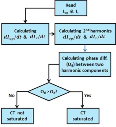
An algorithm has been developed to detect CT saturation by comparing the angle
difference between the second harmonics of the rate of change of operating current and the
rate of change of restrained current [34]. In this algorithm, the phase between the second
harmonic of the derivatives of the operating current and restrain current is estimated and
compared against the threshold value.
1.8 Scope of Thesis
The purpose of this research is to develop a fault discrimination algorithm that is based
on newly defined partial operating current characteristics of a differential protection zone to
overcome the impact of CT saturation on low impedance current differential protection.
Finally, a bus differential relay is designed by incorporating the proposed fault discrimination
algorithm and its performance is validated by an extensive experimental study. The detail scope
of work of the thesis is presented below:
o Mathematical development of the partial operating current characteristics.
o Development of the proposed fault discrimination algorithm.
o Designing of a bus differential relay by incorporating the proposed fault
discrimination algorithm as well as a supervisory technique based on CT
saturation detection algorithm to ensure high sensitivity for high impedance
internal fault conditions.
o Modeling the proposed bus differential relay in Matlab platform.
o Modeling a three bus test system in EMTP which includes all possible elements
of power systems such as transmission line, generator (active source) and load
o Simulating all possible bus faults (12 scenarios) and finding the responses of
proposed relay.
o Comparing results with two latest existing methods, namely, delta phase angle
Chapter 2
2 Mathematical Modeling
In this chapter, mathematical modeling of differential protection principle and current
transformer (CT) saturation are discussed in detail. Different existing methods to discriminate
internal and external faults are explained.
2.1 Differential Protection Principle
Power systems can be divided into different blocks or units such as generator,
transmission line, transformer, bus and motor etc. Protection systems are applied to the system
can be classified into two categories such as unit protection or non-unit protection. Differential
protection is the unit protection system which is applied to protect a particular unit. Unit is
known as zone in protection terminology which is equivalent to simple electrical node. The unit
or zone is bounded by CT locations.
2.1.1 Basics of Differential Protection
Kirchhoff's current law is the principle of conservation of electric charge which implies
that: at any node (junction) in an electrical circuit, the sum of currents flowing into that node is
equal to the sum of currents flowing out of that node, or equivalently the algebraic sum of
Figure 2.1: Electrical node or junction [35]
Recalling that current is a signed (positive or negative) quantity reflecting direction
towards or away from a node; this principle can be stated as:
∑ 𝐼𝑘 = 0 (2.1)
𝑛
𝑘=1
Where n is the total number of branches with currents flowing towards or away from
the node. This formula is valid for complex currents:
∑ 𝐼⃗𝑘 = 0 (2.2)
𝑛
𝑘=1
The law is based on the conservation of charge whereby the charge (measured in
coulombs) is the product of the current (in amperes) and the time (in seconds). Differential
protection works based on above mentioned Kirchhoff’s current law. According to Kirchhoff’s
zone [35]. In power system, zone can be two terminals such as transformer, transmission line
etc. or multi terminals such as busbar.
Figure 2.2: Two terminal zone under normal condition
In case of two terminal zone as shown in Figure 2.2, when system is normal
𝐼𝑖𝑛 = 𝐼𝑜𝑢𝑡 (2.3)
However, if there is any fault in the system as shown in Figure 2.3
𝐼𝑖𝑛 ≠ 𝐼𝑜𝑢𝑡 (2.4)
Figure 2.3: Two terminal zone under fault condition
With multi terminal zone as shown in Figure 2.4, when system is normal
𝐼1− 𝐼2− 𝐼3 = 0 (2.5)
Considering phasor of the currents, Equation (2.5) can be rewrite as
𝐼1+ 𝐼2+ 𝐼3 = 0 (2.6)
Eq. (2.6) shows in normal system condition, vector summation of all terminal currents
must be equal to zero.
Figure 2.4: Multi terminal zone under normal condition
With multi terminal zone as shown in Figure 2.5, when system is faulty
𝐼𝑖𝑛 ≠ 𝐼𝑜𝑢𝑡
𝐼2+ 𝐼3 ≠ 𝐼1
𝐼1− 𝐼2− 𝐼3 ≠ 0 (2.7)
Considering phasor of the currents, Equation (2.7) can be rewrite as
Figure 2.5: Multi terminal zone under fault condition
Eq. (2.8) shows in abnormal or faulty system condition, vector summation of all terminal
currents is not equal to zero.
2.1.3 Restrained differential Protection
Practically, summation of CT secondary currents is not zero even for normal operating
conditions due to the mismatch of CT ratio and burden. Hence there is some spill current
flowing through the relay in normal operating conditions which is known as false operating
current. It becomes high during high loading conditions or high system congestion. To
overcome these issues, the concept of restrained current has been adapted with low
impedance differential scheme. This modified scheme is also known as percentage restrained
differential protection. In this scheme, the operating current is compared with the restrained
Figure 2.6: Characteristics curve of double slope restrained differential relay
The definition of operating current is
𝐼𝑜𝑝 = |𝐼1+ 𝐼2+ ⋯ + 𝐼𝑛| (2.9)
n represents number of terminal of the zone to be protected.
There are several mathematical definitions of restrained current such as
𝐼𝑟 = 0.5(|𝐼1| + |𝐼2| + ⋯ + |𝐼𝑛|) (2.10)
𝐼𝑟 = max(|𝐼1|, |𝐼2|, … |𝐼𝑛|) (2.11)
Usually, restrained current defined by Eq. (2.10) is most widely used. The characteristics
of percentage restrained differential scheme can be expressed mathematically as follows:
𝐼𝑓 𝐼𝑟 < 𝐼𝑟0 , then:
𝐼𝑜𝑝> 𝑆1(𝐼𝑟− 𝐼𝑟𝑜) + 𝐼𝑜𝑝0 → 𝑇𝑟𝑖𝑝 𝐼𝑜𝑝 < 𝑆1(𝐼𝑟− 𝐼𝑟0) + 𝐼𝑜𝑝0→ 𝑁𝑜 𝑇𝑟𝑖𝑝
𝐼𝑓 𝐼𝑟 > 𝐼𝑟1 , then:
𝐼𝑜𝑝 > 𝑆1(𝐼𝑟1− 𝐼𝑟𝑜) + 𝑆2(𝐼𝑟− 𝐼𝑟1) + 𝐼𝑜𝑝0 → 𝑇𝑟𝑖𝑝
𝐼𝑜𝑝< 𝑆1(𝐼𝑟1− 𝐼𝑟0) + 𝑆2(𝐼𝑟− 𝐼𝑟1) + 𝐼𝑜𝑝0→ 𝑁𝑜 𝑇𝑟𝑖𝑝
S1 and S2 are the slopes. The value of S1 varies from 0.4 to 0.7 and value of S2 varies from
0.5 to 0.75 [36]. Iop0, Iro and Ir1 are the relay settings and their values depend on system
parameters.
2.2 Mathematical Modeling of CT Saturation
The circuit model of current transformer (CT) is shown in Figure 2.7.
Figure 2.7: CT Circuit model [37]
The excitation characteristic of the CT is invariably a plot of secondary rms voltage
Figure 2.8: CT excitation curve [37]
Two parameters S and VS can be extracted from the curve as shown in Figure 2.9.
Figure 2.9: Method of determining the parameters Vs and S [37]
The reason for choosing the saturation voltage, Vs, at the point where the excitation
current is ten amps, is that this is the definition used in the standard [37]. The straight line
curve with slope 1/S shown in Figure 2.9 is not linear. It is a curve defined mathematically as
𝑙𝑜𝑔𝑉𝑒 =1
where Vi is the value of Ve for Ie=1, that is for log Ie=0.
After removing the logs from both sides:
𝑉𝑒 = 𝑉𝑖𝐼𝑒
1
𝑆 (2.13)
In order to solve the circuit of Figure 2.7, the instantaneous λ (flux-leakage) versus ie
curve is required. It is postulated [37] that a curve defined as
𝑖𝑒 = 𝐴. 𝜆𝑆 (2.14)
is suitable as long as the exponent S is an odd integer [37]. In order to allow S to be any
positive number, and keep the function odd, the following expression can be used:
𝑖𝑒 = 𝐴. 𝑠𝑔𝑛(𝜆). |𝜆|𝑆 (2.15)
where sgn(λ) is the sign of λ as shown in See Figure 2.10 and A is a constant.
Figure 2.10: Postulated instantaneous values saturation curve [37]
The flux-linkages λ are related to the instantaneous excitation voltage ve by Faraday’s
𝑣𝑒 =
𝑑𝜆
𝑑𝑡 (2.16)
The excitation curve is assumed as sinusoidal voltage, which implies that the
flux-linkages are also sinusoidal
𝑣𝑒 = √2𝑉𝑒cos (𝜔𝑡) (2.17)
𝜆 = ∫ 𝑣𝑒𝑑𝑡 = ∫ √2𝑉𝑒cos(𝜔𝑡) 𝑑𝑡 =
1
𝜔√2𝑉𝑒sin(𝜔𝑡) (2.18)
The excitation current is non-sinusoidal, since it is a Sth order function of λ as
𝑖𝑒 = 𝐴𝜆𝑆 = 𝐴 [1
𝜔√2𝑉𝑒sin(𝜔𝑡)]
𝑆
= 𝐴 [1 𝜔√2𝑉𝑒]
𝑆
sin𝑆(𝜔𝑡) (2.19)
The rms value of this current is
𝐼𝑒= √ 1 2𝜋∫
2𝜋
0
𝑖𝑒2𝑑𝑡 = √ 1
2𝜋∫
2𝜋
0
𝐴2[√2𝑉𝑒
𝜔 ]
2𝑆
sin2𝑆 (𝜔𝑡)𝑑𝑡
= 𝐴 [√2𝑉𝑒 𝜔 ]
𝑆
√1
2𝜋∫ 2𝜋
0 sin2𝑆 (𝜔𝑡)𝑑𝑡 (2.20)
Now, the ratio of rms-value-to-peak-value of the excitation current can be defined as
𝑅𝑃 = 𝑟𝑚𝑠
𝑝𝑒𝑎𝑘 (2.21)
𝑅𝑃 = √ 1
2𝜋 ∫
2𝜋
0 (√2𝐼𝑒) 2
sin2𝑆 (𝜔𝑡)𝑑𝑡
√2𝐼𝑒
= √ 1 2𝜋∫
2𝜋
0
sin2𝑆 (𝜔𝑡)𝑑𝑡 (2.22)
The difference between RP for a sinusoid and RP the assumed excitation current
waveform is illustrated in Figure 2.11. The factor RP gets smaller as the value of S increases.
Figure 2.11: Comparison of the rms/peak relationship for two wave shapes [37]
Substituting the result Eq. (2.22) into Eq. (2.20), yields
𝐼𝑒 = 𝐴 [√2𝑉𝑒 𝜔 ]
𝑆
𝑅𝑃 (2.23) As Ve=Vs when Ie=10 , substituting,
10 = 𝐴 [√2𝑉𝑠 𝜔 ]
𝑆
𝑅𝑃
𝐴 = 10𝜔
𝑆
(√2𝑉𝑆) 𝑆
1
𝑅𝑃 (2.24)
Substituting the value of A in Eq. (2.15), yields
𝑖𝑒 = 𝑠𝑔𝑛(𝜆)
10𝜔𝑆
(√2𝑉𝑆) 𝑆
1 𝑅𝑃 |𝜆|
𝑆 (2.25)
Now, applying Kirchhoff’s Voltage Law around the right-hand loop of the circuit in Figure
2.7, yields
𝑣𝑒− (𝑖𝑠 − 𝑖𝑒)𝑅𝑡− 𝐿𝑏
𝑑
𝑑𝑡[𝑖𝑠− 𝑖𝑒] = 0 (2.26)
The solution of is and its derivative are [36]:
𝑖𝑠 = 𝑖1 𝑁=
√2𝐼𝑝
𝑁 [𝑂𝑓𝑓. 𝑒
−𝑡𝜏 − cos (𝜔𝑡 − cos−1𝑂𝑓𝑓)]
𝑑𝑖𝑠 𝑑𝑡 = √2𝐼𝑝 𝑁 [− 𝑂𝑓𝑓 𝜔 . 𝑒 −𝑡𝜏 + 1
𝜔cos (𝜔𝑡 − cos
−1𝑂𝑓𝑓)] (2.27)
Where Off = per unit dc-offset magnitude and 𝜏 = system time constant. Note that 𝑑𝑖𝑒 𝑑𝑡 = 𝑑𝑖𝑒 𝑑𝜆 . 𝑑𝜆
𝑑𝑡 (2.28) 𝑑𝑖𝑒
𝑑𝑡 = 𝐴. 𝑆. |𝜆|
Finally, with substitutions and manipulation, equation (2.26) can be re-written as
𝑑𝜆
𝑑𝑡 [1 + 𝐿𝑏𝐴 𝑆 |𝜆|
𝑆−1] = −𝑅
𝑡𝑖𝑒+ 𝑅𝑡𝑖𝑠+ 𝐿𝑏
𝑑𝑖𝑠
𝑑𝑡 (2.30)
This first-order nonlinear differential equation is solved for λ(t) using standard numerical
analysis techniques. Then the excitation current ie is given by equation (2.14), and the actual
secondary current is
𝑖2= 𝑖𝑠− 𝑖𝑒 (2.31)
In case of the single-valued saturation curve, conventional remanence is not possible
because non-zeroλ cannot occur for zero ie. However, remanence can be approximated very
closely by simply assuming that the initial excitation current is non-zero. For convenience, λrem
is expressed in per unit of Vs as shown in Figure 2.12.
𝜆𝑟𝑒𝑚=
𝑥 𝑉𝑆
(2.32)
In order to specify λrem accurately, x must be specified no greater than Vknee[37].
2.3 Existing Methods to Discriminate Internal and External Faults
Dual slope characteristic of percentage differential relay provides some protection
against current transformer (CT) saturation; however, it is not enough for all practical external
fault scenarios. Researchers have proposed various techniques and schemes to discriminate
internal and external fault for providing more security for differential protection against CT
saturation. Mathematical modeling of two latest methods is presented in this section.
2.3.1 Phase Angle Comparison Method
Phase Angle Comparison Method principle essentially monitors the phase angle
relationships with the incoming and the outgoing currents of a protected zone. As
implementing the phase angle in real time is a challenging task, the phase angles of the
combination of various incoming and outgoing currents are executed in real-time using the
dot-product method to compare whether the phase angle difference is within the threshold value
to declare whether the fault is internal or external (Figure 2.13 & 2.14) to the zone of
protection [13] [24] [39].
For two currents 𝐼𝑖 & 𝐼𝑗, the dot product is
𝐼𝑖. 𝐼𝑗 = |𝐼𝑖| |𝐼𝑗|𝑐𝑜𝑠𝜃𝑖𝑗
𝑐𝑜𝑠𝜃𝑖𝑗 = 𝐼𝑖 . 𝐼𝑗
|𝐼𝑖| |𝐼𝑗| (2.33) Where, the term 𝑐𝑜𝑠𝜃𝑖𝑗 directly indicates the phase difference between the two
vectors. For n-terminals protected zone,
If 𝑐𝑜𝑠𝜃𝑖𝑗 is greater than a specific threshold value (𝑐𝑜𝑠𝜃0) for all combinations of i and j,
then the metric of Equation 2.34 indicates existence of an internal fault.
𝑐𝑜𝑠𝜃𝑖𝑗 > 𝑐𝑜𝑠𝜃0 𝐼𝑖 . 𝐼𝑗
|𝐼𝑖| |𝐼𝑗|> 𝑐𝑜𝑠𝜃0
𝐼𝑖. 𝐼𝑗 > |𝐼𝑖| |𝐼𝑗|𝑐𝑜𝑠𝜃0 (2.34)
Any phasor current with a magnitude less than a specific set value (𝐼0) is excluded from this algorithm.
Figure 2.13: External Fault scenario
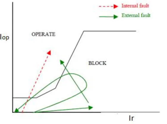
2.3.2 Differential Rate of Change Method (ROCOD)
During faults, operating current (𝐼𝑜𝑝) and restrained current (𝐼𝑟) change as Figure 2.15. From the trajectory of 𝐼𝑜𝑝 and 𝐼𝑟 during internal and external faults, it can be concluded that
the rate of change of 𝐼𝑜𝑝 is greater than the rate of change of 𝐼𝑟for an internal fault, whereas
for external faults, the rate of change of 𝐼𝑜𝑝 is less than the rate of change of 𝐼𝑟 [24] [25] [39].
Figure 2.15: Trajectory of 𝑰𝒐𝒑 and 𝑰𝒓 [24]
Equation 2.35 indicates the condition for Internal Faults while External Faults satisfy
Equation 2.36 when using ROCOD.
𝑑𝐼𝑜𝑝 𝑑𝑡 >
𝑑𝐼𝑟
𝑑𝑡 (2.35) 𝑑𝐼𝑜𝑝
𝑑𝑡 < 𝑑𝐼𝑟
The detail logic of differential rate of change method is presented in Figure 2.16. To
declare a fault as an internal fault, the fault needs to satisfy two conditions. First, the rate of
change of operating current (Iop) as well as the rate of change of restraint current (Ir) must be
the positive. To ensure this the rate of change of operating current (Iop) as well as the rate of
change of restraint current (Ir) are compared with a small positive threshold value (Ith).
Secondly, the rate of change of 𝐼𝑜𝑝 must be greater than the rate of change of 𝐼𝑟.
Figure 2.16: Logic Diagram of Differential Rate of Change Method
This chapter has covered the mathematical development of current differential
protection which includes restraint characteristics. Mathematical modeling of CT saturation as
well as two widely used fault discrimination methods has been described in details. The next
chapter will cover the main contributions of this thesis which includes mathematical modeling
of a proposed fault discrimination algorithm as well as the design details of a differential bus
Chapter 3
3 Thesis Contributions
Chapter 2 has given the insight of differential protection principle, current transformer
(CT) saturation, and existing techniques to discriminate internal and external faults. This
chapter starts by describing the fault discrimination difficulties for low impedance current
balanced differential protection schemes and explains a new methodology to address the
issues. Finally, the design details of a differential bus protection relay are presented which
includes proposed fault discrimination algorithm.
3.1 Problem Statement: Difficulties in Discrimination of Faults
The main concern with bus differential protection is to make it secure from
mal-operation in response to the CT saturation during external faults. During external faults, when
fault current becomes high, CT can get saturated. The CT saturation creates high operating
current which causes the undesired operation of relay. The primary reason for such
mal-operation is the fact that the traditional differential principle relies exclusively on current
magnitude rather than directionality for tripping decisions.
There are several existing techniques to discriminate between internal fault and
external fault for bus differential protection. CT saturation detection supervision is one of the
earliest techniques, however, it fails to provide complete solution as CT can also be saturated
during internal fault. Phase angle comparison is very widely used technique, although it has
computational complexity when large numbers of input currents are involved. Moreover,
which may cause the phase angles function to block the relay from tripping for the internal
fault. The latest proposed method is based on rate of change of operating and restrained
current which has limitation on fast CT saturation condition.
3.2 Objective
The main objective of this thesis is to come up with an effective algorithm to
discriminate between internal and external faults. Based on this algorithm, a differential relay
will be designed for bus protection which is capable of overcoming the impact of CT saturation.
This thesis presents a new fault discrimination algorithm by defining partial operating current
characteristics of a differential protection zone based on investigating its performance on
busbar differential protection.
3.3 Mathematical Model of Partial Operating Current and Proposed Algorithm
In power system, differential protection zones are two types; two terminals such as
transformer or transmission line and multi terminals such as busbar. Figure 3.1 shows a typical
multi terminals protection zone which has three terminals. Terminal is a branch-circuit where
transmission line or generator or load is connected. This is the single phase representation of a
three phase system. Differential protection works on phase wise differential zone which means
all elements of a zone must be in same phase. Although Figure 3.1 displays a zone with three
terminal, physical zone may have more than three terminal which will be addressed in the later
![Figure 2.1: Electrical node or junction [35]](https://thumb-us.123doks.com/thumbv2/123dok_us/8922665.1843099/33.612.265.420.71.233/figure-electrical-node-or-junction.webp)
![Figure 2.10: Postulated instantaneous values saturation curve [37]](https://thumb-us.123doks.com/thumbv2/123dok_us/8922665.1843099/40.612.257.389.450.588/figure-postulated-instantaneous-values-saturation-curve.webp)
![Figure 3.13: Trajectory of operating and restrained current [34]](https://thumb-us.123doks.com/thumbv2/123dok_us/8922665.1843099/63.612.83.530.440.668/figure-trajectory-operating-restrained-current.webp)

![Table 5.1: CT parameters [43]](https://thumb-us.123doks.com/thumbv2/123dok_us/8922665.1843099/70.612.82.540.185.466/table-ct-parameters.webp)