International Journal of Electronics Communication and Computer Engineering Volume 4, Issue 4, ISSN (Online): 2249–071X, ISSN (Print): 2278–4209
Adaptive Finite Element Analysis for Optimized Design
of Coaxial Antenna Fed DI Water-Stowed Waveguide
Applicator for Therapeutic Local Hyperthermia System
Neeru Malhotra
Associate Professor & Head,Department of ECE DAVIET, Jalandhar [email protected]
Pankaj Kumar
M.Tech. Research Scholar,Department of ECE SLIET Longowal [email protected]
Anupma Marwaha
Associate Professor, Department of ECE SLIET Longowal [email protected]Ajay Kumar
Associate Professor,Department of ECE BCET Gurdaspur [email protected]
Abstract–In this paper, coaxial antenna is used to couple electromagnetic energy into waveguide coupled applicator. The water-stowed, indirectly cooled optimized coaxial coupled waveguide applicator has been developed for local hyperthermia applications using Adaptive Finite Element Method. High permittivity deionized (DI) water is used for indirect cooling in bolus for reduced size of waveguide applicator. The water loading also provides a good coupling of the radiated power into body tissue. The optimization is hence achieved and verified by measuring S parameter and specific absorption rates (SAR) which are found to be satisfactory for localized superficial hyperthermia treatments. The results indicate that coaxial coupling provides better focusing of microwave energy.
Keywords – Adaptive Finite Element Method (A-FEM), Deionized (DI) Water Waveguide Applicator, Co-Axial Coupling, Specific Absorption Rate (SAR).
I. I
NTRODUCTIONHyperthermia (also called thermal therapy or thermotherapy) is a type of cancer treatment in which body tissue is exposed to high temperatures (up to 45°C). The process reduces the tumor size by killing cancer cells and damagingproteinsand structures within cells [1]. Hyperthermia is used with other forms of cancer therapy, such as radiation therapy and chemotherapy [2]. The basic idea behind this treatment is to create an artificial fever of 41- 45ºC in the body of the patient without damaging the benign tissue. Different studies have shown that moderate temperatures can damage and kill cancer cells, causing minimal injury to normal tissues. Hyperthermia may make some cancer cells more sensitive to radiation or harm other cancer cells that radiation cannot damage.Numerous clinical trials have studied hyperthermia in combination with radiation therapy and/or chemotherapy. The combination of hyperthermia with these therapies has been conducted for many kinds of cancers, including liver, cervix,sarcoma, appendix, melanoma, and cancers of the head and brain,neck, lung, esophagus, bladder, rectum,breast,and mesothelioma [1,3-7,10].
Several methods of hyperthermia are currently under study, including local, regional, and whole-body hyperthermia (1,3–9). Inlocal hyperthermia, heat is applied to a small tumor area using various techniques for delivering energy to heat the tumor. Presently the methods used to apply heat include radio-frequency,ultrasound and
body, there are different approaches to local hyperthermia. Interstitial techniques are used to treat tumors deep seated within the body. This technique allows the tumor to be heated to higher temperatures than external techniques. The heat source, RF or microwave, is then inserted into the probe which is inserted into the tumor. External (Superficial) approaches are however used to treat tumors that are on surface or just below the skin. Accordingly, external applicators apparently placed near the affected area tofocus energy on the tumor to raise its temperature. In this paper, water-stowed, indirectly cooled coaxial coupled waveguide applicator has been developed for external (superficial) hyperthermia applications [11-12].
II. C
OAXIAL TOW
AVEGUIDEC
OUPLEDA
PPLICATORThe choice of a suitable model depends on the frequency of operation, between 300 MHz and 4.2 GHz, the stratified model may be the most appropriate one. In the present work, model is designed for working frequency of 485 MHz, which is one of the ISM (Industrial Scientific Medical) frequencies. At high frequencies the depth of operation is too small, while at lower frequencies, focusing of the field is difficult. It will also produce high surface temperature because the peak temperatures are located nearer to the surface. However, this is expected since by increasing the frequency of operation, the depth of field penetration decreases in the biomass. If, on the other hand, lower frequencies are used, peak temperatures will be sensed deeper in the muscle, but they will be lower, so more power will be required to achieve specified level of heating at lower frequencies [13-15]. Indirect cooling via water bolus helps regulating surface temperature homogeneity during the hyperthermia. Non-invasive hyperthermia systems using waveguide antenna are less traumatic to patients which also minimize the risk of mixing abnormal cells with healthy tissues. The electromagnetic energy radiated from the waveguide antenna is used to raise the temperature in tumor area in the therapeutic range of 40-45 °C to reduce the tumor volume.
A. Deionized Water
Copyright © 2013 IJECCE, All right reserved
International Journal of Electronics Communication and Computer Engineering Volume 4, Issue 4, ISSN (Online): 2249–071X, ISSN (Print): 2278–4209
can be easily achieved. Moreover, the rather high value of the real part of deionized water permittivity (εw~ 81) permits a considerable reduction (~ 9 times) in applicator aperture dimensions, which is very important in trying to achieve good directivity. Furthermore, it was decided to give priority to a small spillover radiation specification rather than the requirement to cover the maximum area of 10x 10 cm2 with asingle applicator. The maximum area can be heated by simultaneously using several applicators or even by scanninga single applicator on the tumor surface. Therefore,the waveguide dimensions were chosen to the minimum so that the dominant TE10mode should be transmitted.
B. Coaxial To Waveguide Coupled Applicator
Design
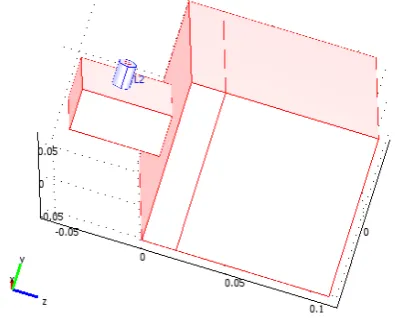
Fig. 1 depicts the perspective view of the developed coaxial coupled applicator is shown.
Fig.1. Perspective view of the developed applicator The energy is fed into the cross-sectional area a x b (a = 2.4 cm, b = 4.8 cm) of the waveguide through a coaxial-to-waveguide coupled coaxial-to-waveguide transition by utilizing a coaxial probe-typeantenna inside the waveguide. The probe conductor, soldered to the central conductor of an N-type coaxial connector, was extended near to the opposite wall of the waveguide. The length l of one side of the short-circuitedwaveguide section was chosen equal to
λg/2, where λgis the wavelength inside the waveguide. The
λgof TE10mode is given by the relation
= (1)
where is the real part of the DI water complex permittivity, is the free-space wavelength,
2 '
/10 w
c c a
f is the TE10mode cutoff frequency (c= 3 x 10⁸m/s), and is the radiation frequency. The cooling chamber or water bolus is the portion between the waveguide and the muscle phantom as shown in Fig.1, isolates the waveguide cavity from the phantom. By circulating DI water through the cooling chamber, the antenna temperature was kept constant without any problem up to 100-W transmitted power levels.
III. M
ETHODOLOGYFEM has been extensively used in simulation of microwave antenna applicators because the computer simulations determine the optimal antenna design for the purpose of optimal power application and effectively localized thermal lesion. This method carries on the processing in three stages: Pre-processing, Processing and Post-processing. In Pre-processing the whole structure is divided into elementary sub domains, which are called finite elements and the field equations are applied to each of them. In processing the FE methods are essentially based on determination of the distribution of electric and magnetic fields in the structures under study, based on the
solution of Maxwell’s equations. The post processing
performs analysis of results obtained by determination of other parameters based on the field distributions.
To solve electromagnetic problems with boundaries values, it is essential to formulate the problem in terms of magnetic vector potential A and the electric scalar potential V.
) 3 (
) 2 (
A V E
A B
The electromagnetic field radiated in given tissue by an appropriate antenna can be determined by solving the Maxwell's equation stated below with the knowledge of tissue electromagnetic properties.
Discussing the most fundamental concepts of dielectric constant (relative dielectric constant) and the loss
tangent tanδ, the dielectric constant tells a lot about reflection properties and reduction in wavelength whereas the loss tangent is reduced from the free-space value by the ratio c. Wave reflection at a surface of a material will increase as increases. For example, for a substance like water where ~60, the power reflection is about 60%.
The loss tangent is a measure of how absorptive the material is, or how quickly it causes a wave to attenuate as it propagates in the material. A simple formula for penetration depth D, the depth at which the power density is reduced by l/e2or the fields by l/e, is
) 4 ( tan
319 . 0 tan 319 .
0 0
D
where0 is free space wavelength.The energy or power absorbed by the body as the wave attenuates produces local heating at a rate called the specific absorption rate, and is given by
/ (5)tan 2
1 2
0 E w kg
SAR in
Where,
SAR is the power transferred to the absorber by the electric field in the body
is the mass density of the body, in kg/m3 0
is the permittivity of free space, in farads/m
International Journal of Electronics Communication and Computer Engineering Volume 4, Issue 4, ISSN (Online): 2249–071X, ISSN (Print): 2278–4209
in
E is the electric field in volts/m at the point in in the body, with the subscript "in" to emphasize that the field inside the body is not the same as the field in the incident radiation.
A. Maxwell Equations
) 7 (
) 6 (
E j H
H j E
Where, E and H are Electric and magnetic field vectors respectively. and are permeability and permittivity respectively.
The total fields obtained due to electric and magnetic vector potential are obtained as:
) 9 ( )
, ( 1
) 8 ( 1
) , (
V w
j V
j A H
A A
w j jwA E
The position and orientation of the applicator are optimized in order to achieve better distribution of SAR (Specific Absorption Rate) in treated area. SAR determines the quantity of electromagnetic field exposition andit is related to E- field by [6].
The heat transfer inside a biological tissue is described
by bio heat equation proposed by Penne’s [13], which
relates TE waves with temperature increase in tissue. The bio heat equation is defined as:
b b b
b
met exts V k T C T T Q Q
T
C
(10)
where, s
is a time scaling coefficient is the tissue density
C is the specific heat of tissue
k is the tissue thermal conductivity tensor
b
is the density of blood b
C is the specific heat of blood
b
is the blood profusion rate b
T is the arterial blood temperature
met
Q is the heat source from metabolism ext
Q is the specific heat source
The dimensions of the waveguide aperture are calculated using the following equations:
) 12 ( 2
) 11 ( 2
1 0 0 a b
f a
r r c
Where, a and b are the height and width of the waveguide aperture, f is the cut-off frequency,c
are the permeability of free space and the material inside the waveguide respectively,
are the permittivity of free space and the material inside the waveguide respectively.
For calculating the waveguide height, it is necessary to know the wavelength, which is given by the equation:
1
B. Model Formulation
Coaxial lines cross-coupled to a waveguide are commonly used power combining structures. The problem of a single coaxial line cross-coupled to a rectangular waveguide has been studied in [14,15]. In the problem considered in this paper, it is assumed that the waveguide and coaxial line are perfectly conducting and that only the TEM mode can propagate in the coaxial line at the frequency of interest. The analysis presented here is applicable to the case where the waveguide (assumed deionized water as dielectric) is perfectly matched at both waveguide ports.
FEM based COMSOL Multiphysics software has been used for the simulative implementation of applicator, which is a powerful interactive environment for modeling and solving all kinds of scientific and engineering problems based on partial differential equations (PDEs). With this software, one can extend conventional models for one type of physics into Multiphysics models that solve several coupled physics phenomenaand do so simultaneously.
For more realistic implementation, 3D model has been created which consisted of a waveguide applicator, water bolus and the muscle phantom.
Copyright © 2013 IJECCE, All right reserved
International Journal of Electronics Communication and Computer Engineering Volume 4, Issue 4, ISSN (Online): 2249–071X, ISSN (Print): 2278–4209
The mesh consisted of 16377 elements and 109472 numbers of degrees of freedom. The governing equations of the physics are then solved inside each of these sub-domains. The parametric solver is used to solve the model. The execution has been performed using Intel(R) Core(TM) i7-3770k @3.40 GHz 3.90GHz CPU with simulation time of 1088.97 s.
Table 1: Mesh statistics of the generated mesh Number of degrees of freedom 109472
Number of mesh points 3346
Number of elements 16377
Tetrahedral 16377
Prism 0
Hexahedral 0
Number of boundary elements 2998
Triangular 2998
Quadrilateral 0
Number of edge elements 343
Number of vertex elements 40
Minimum element quality 0.346
Element volume ratio 0
Table 2: Scalar variables
Name Expression Description
eps_w 81 water permittivity
sigma_w .05[S/m] water conductivity
eps_m 54 muscles phantom
permittivity
sigma_m 0.8[S/m] muscle phantom
conductivity rho_m 1000[kg/m^3] muscle phantom density
eps_ptfe 2.2
sigma_ptfe 0
C. GMRES Linear System Solver
This linear system solver uses the restarted GMRES (generalized minimum residual) method. This is an iterative method for general linear systems of the form Ax = b. For fast convergence it is important to use an appropriate preconditioner.
There is no guarantee that a restarted GMRES converges for a small restart value. A larger restart value increases the robustness of the interactive procedure, but it also increases memory use and computational time. For large problems, the computational cost is often very large to produce a preconditioner of such a high quality that the termination criteria are fulfilled for a small number of iterations and for a small restart value. For those problems it is often advantageous to set up a preconditioner with a somewhat lesser quality and instead increase the restart value or iterate more steps. Doing so typically increases the condition number for the preconditioned system, so an increase in the error-estimate factor might be needed as well.Two slightly different versions of GMRES are available in COMSOL Multiphysics. The difference between these two versions is whether left or right
preconditioning is used. Normally, the two versions of GMRES have similar convergence behavior.
Fig.3. SAR heat distribution in the muscle phantom
IV. R
ESULTS ANDD
ISCUSSIONThe performance analysis is done by evaluating3D heat distribution and reflection coefficient S11parameters. Fig.3 show the 3D heat distribution within the muscle phantom depicting spherical leison and localized heating pattern. Fig.4 further plots the values of S11 versus frequency to analyze the impedance matching for the different cases. It is evident from the plots that at operating frequency of 485 MHz, S11reaches a minimum of -15.6 dB indicating good impedance matching for waveguide loaded with deionized water having relative dielectric constant, εr = 81.Fig. 5 illustrates the convergence plot obtained during simulation of the problem using GMRES (Generalized minimal residual) method. Fig.6. depicts the resistive heating plot which gives the insight about the amount of power converted into heat at various penetration depths inside the tissue. The maximum power absorption is achieved and the focusing of heat distribution in the muscle phantom is therefore best localized. Also for commercial point of view water as dielectric is a better and cheaper option. As the permittivity of the material filled in the antenna applicator increases the optimized performance is obtained with reduced dimensions of the waveguide applicator.
Fig.4. Impedance matching (S11) plot of coaxial to waveguide coupled applicator.
Copyright © 2013 IJECCE, All right reserved
International Journal of Electronics Communication and Computer Engineering Volume 4, Issue 4, ISSN (Online): 2249–071X, ISSN (Print): 2278–4209
The mesh consisted of 16377 elements and 109472 numbers of degrees of freedom. The governing equations of the physics are then solved inside each of these sub-domains. The parametric solver is used to solve the model. The execution has been performed using Intel(R) Core(TM) i7-3770k @3.40 GHz 3.90GHz CPU with simulation time of 1088.97 s.
Table 1: Mesh statistics of the generated mesh Number of degrees of freedom 109472
Number of mesh points 3346
Number of elements 16377
Tetrahedral 16377
Prism 0
Hexahedral 0
Number of boundary elements 2998
Triangular 2998
Quadrilateral 0
Number of edge elements 343
Number of vertex elements 40
Minimum element quality 0.346
Element volume ratio 0
Table 2: Scalar variables
Name Expression Description
eps_w 81 water permittivity
sigma_w .05[S/m] water conductivity
eps_m 54 muscles phantom
permittivity
sigma_m 0.8[S/m] muscle phantom
conductivity rho_m 1000[kg/m^3] muscle phantom density
eps_ptfe 2.2
sigma_ptfe 0
C. GMRES Linear System Solver
This linear system solver uses the restarted GMRES (generalized minimum residual) method. This is an iterative method for general linear systems of the form Ax = b. For fast convergence it is important to use an appropriate preconditioner.
There is no guarantee that a restarted GMRES converges for a small restart value. A larger restart value increases the robustness of the interactive procedure, but it also increases memory use and computational time. For large problems, the computational cost is often very large to produce a preconditioner of such a high quality that the termination criteria are fulfilled for a small number of iterations and for a small restart value. For those problems it is often advantageous to set up a preconditioner with a somewhat lesser quality and instead increase the restart value or iterate more steps. Doing so typically increases the condition number for the preconditioned system, so an increase in the error-estimate factor might be needed as well.Two slightly different versions of GMRES are available in COMSOL Multiphysics. The difference between these two versions is whether left or right
preconditioning is used. Normally, the two versions of GMRES have similar convergence behavior.
Fig.3. SAR heat distribution in the muscle phantom
IV. R
ESULTS ANDD
ISCUSSIONThe performance analysis is done by evaluating3D heat distribution and reflection coefficient S11parameters. Fig.3 show the 3D heat distribution within the muscle phantom depicting spherical leison and localized heating pattern. Fig.4 further plots the values of S11 versus frequency to analyze the impedance matching for the different cases. It is evident from the plots that at operating frequency of 485 MHz, S11reaches a minimum of -15.6 dB indicating good impedance matching for waveguide loaded with deionized water having relative dielectric constant, εr = 81.Fig. 5 illustrates the convergence plot obtained during simulation of the problem using GMRES (Generalized minimal residual) method. Fig.6. depicts the resistive heating plot which gives the insight about the amount of power converted into heat at various penetration depths inside the tissue. The maximum power absorption is achieved and the focusing of heat distribution in the muscle phantom is therefore best localized. Also for commercial point of view water as dielectric is a better and cheaper option. As the permittivity of the material filled in the antenna applicator increases the optimized performance is obtained with reduced dimensions of the waveguide applicator.
International Journal of Electronics Communication and Computer Engineering Volume 4, Issue 4, ISSN (Online): 2249–071X, ISSN (Print): 2278–4209
Fig.5. Convergence plot while solving the problem using GMRES (Generalized minimal residual) method.
Fig.6. Resistive heating plot
V. C
ONCLUSIONSThe 3D simulation model of water-stowed, indirectly cooled coaxial coupled waveguide applicator waveguide for local hyperthermia treatmenthas been done using FEM based COMSOL Multiphysics ver. 3.5a.Adaptive Finite element full-wave modeling has been performed to predict to a high degree of accuracy the performance of 3D model of the applicator.Good thermal and electrical stability is achieved for radiation powers up to 100 W. The work also performs the analysis of field distribution in terms of resistive heating distribution.In the next step of research the formulation of 3D model will be extended for analysis of various favorable antenna types connected with the coaxial probe inside the waveguide to achieve better temperature goals and more spherical lesion inside the tissue.
VI. R
EFERENCES[1] Vander Zee J. Heating, “The Patient: A Promising Approach”, Annals of Oncology, 2002; 3(8):1173–1184.
[2] Hildebrandt B, Wust P, AhlersO, et al. “The Cellular and Molecular Basis of Hyperthermia”,Critical Reviewsin Oncology/Hematology 2002; 43(1): 33–56.
[3] Wust P, Hildebrandt B, Sreenivasa G, et al. “Hyperthermia in Combined Treatment of Cancer”,The Lancet Oncology 2002; 3(8):487–497.
[4] Alexander HR. Isolation perfusion. In: DeVita VT Jr., Hellman S, Rosenberg SA, editors,“Cancer: Principles and Practice of Oncology”, Vol. 1 and 2. 6th ed. Philadelphia: Lippincott Williams and Wilkins, 2001.
[5] Falk MH, Issels RD,“Hyperthermia in Oncology”,International Journal of Hyperthermia 2001; 17(1):1–18.
Peritoneal Mesothelioma Undergoing Surgical Debulking and Intraperitoneal Chemotherapy”,Journal of Clinical Oncology 2003; 21(24):4560–4567.
[7] Chang E, Alexander HR, Libutti SK, et al. “Laparoscopic Continuous Hyperthermic Peritoneal Perfusion”,Journal of the American College of Surgeons 2001; 193(2):225–229.
[8] J. van der Zee, “Hyperthermia: APotent Enhancer of Radiotherapy”, Anals of Oncology 13: 1173-1184, 2002. [9] R. W. Y. Habash, “Non-invasive Microwave Hyperthermia”,
Indian institute of science, 1994.
[10] Vorst, A. V., A. Rosen, and Y. Kotsuka, “RF/Microwave Interaction with Biological Tissues”, John Wiley, 2006. [11] S. Jacobsen, P. Stauffer, “Can We Settle with Single-band
Radiometric Temperature Monitoring during Hyperthermia Treatment of Chestwall Recurrence of Breast Cancer using a Dual-mode Transceiving Applicator”, Phys. Med. Biol. 52 (2007) 911-928.
[12] Williamson A.G., “Analysis andModeling of Two Gap Coaxial LineRectangular Waveguide Junctions”, IEEE Trans. Microw. Theory Tech., 1983, 31, (3), pp. 295–302.
[13] Allen, P.J., Bates, B.D., and Khan, P.J., “Analysis and Use of HarklessDiode Mount for IMPATT Oscillators”, IEEE MTT-S Int. Microw. Symp. Dig., June 1982, pp. 138–141.
[14] RF and Heat Transfer Module tutorials at www.comsol.com. [15] COMSOL Multiphysics User's guide.
A
UTHOR’
SP
ROFILEMs. Neeru Malhotra
is presently working as Associate Professor and Head of Department of Electronics & Communication Engineering at D.A.V. Institute of Engineering & Technology, Jalandhar (Pb), India.. She is pursuing her Ph. D. from PTU, Jalndhar. M.Tech from PTU Jalndhar, India, B.Tech. from S.L.I.E.T. , Longowal She has 15 years of academic experience. She has authored 15 research papers in International and National journals and 14 research papers in National and International conferences. She has supervised 10 M.Tech. thesis and 04 are under progress. Her areas of interest include Bio-Electromagnetics, Wireless communication and Antenna design.
Mr. Pankaj Kumar
received the B.Tech. from Punjab Technical University, Jalandhar and M.Tech. from SLIET (Deemed University), Longowal, Punjab, India, in electronics and communication engineering, in 2010 and 2013 respectively. In 2011, he worked as electronics faculty at Institution of Electronics and Telecommunication Engineers (IETE), Chandigarh. His current research interests include Multiphysics modeling, antenna modeling and renewable energy resources.
Dr. Anupma Marwaha
is currently Associate Professor at SantLongowal Institute of Engg. & Tech., Logowal (Sangrur). She has done her Ph. D. from GNDU, Amritsar, M.Tech from REC Kurukshetra (Now NIT, Kurukshetra) India, B.E. from Punjab University, Chandigarh. She has 20 years of academic experience. She has authored 25 research papers in International and National journals and 50 research papers in National and International conferences. She has supervised 02 Ph.D. thesis and 10 M.Tech. thesis and 04 are under progress. Her areas of interest include Electromagnetics, Microwave Comm., Wireless communication and Antenna design.
Dr. Ajay Kumar
is presently working as Associate Professor and Head of Department of Electronics & Communication Engineering at Beant College of Engineering & Technology, Gurdaspur (Pb), India. He has over 17 years of teaching experience. His areas of interest include Electromagnetic System Design, Neural Network and Fuzzy Logic, Network Analysis and Signals & Systems. He has over 20
International Journal of Electronics Communication and Computer Engineering Volume 4, Issue 4, ISSN (Online): 2249–071X, ISSN (Print): 2278–4209
Fig.5. Convergence plot while solving the problem using GMRES (Generalized minimal residual) method.
Fig.6. Resistive heating plot
V. C
ONCLUSIONSThe 3D simulation model of water-stowed, indirectly cooled coaxial coupled waveguide applicator waveguide for local hyperthermia treatmenthas been done using FEM based COMSOL Multiphysics ver. 3.5a.Adaptive Finite element full-wave modeling has been performed to predict to a high degree of accuracy the performance of 3D model of the applicator.Good thermal and electrical stability is achieved for radiation powers up to 100 W. The work also performs the analysis of field distribution in terms of resistive heating distribution.In the next step of research the formulation of 3D model will be extended for analysis of various favorable antenna types connected with the coaxial probe inside the waveguide to achieve better temperature goals and more spherical lesion inside the tissue.
VI. R
EFERENCES[1] Vander Zee J. Heating, “The Patient: A Promising Approach”, Annals of Oncology, 2002; 3(8):1173–1184.
[2] Hildebrandt B, Wust P, AhlersO, et al. “The Cellular and Molecular Basis of Hyperthermia”,Critical Reviewsin Oncology/Hematology 2002; 43(1): 33–56.
[3] Wust P, Hildebrandt B, Sreenivasa G, et al. “Hyperthermia in Combined Treatment of Cancer”,The Lancet Oncology 2002; 3(8):487–497.
[4] Alexander HR. Isolation perfusion. In: DeVita VT Jr., Hellman S, Rosenberg SA, editors,“Cancer: Principles and Practice of Oncology”, Vol. 1 and 2. 6th ed. Philadelphia: Lippincott Williams and Wilkins, 2001.
[5] Falk MH, Issels RD,“Hyperthermia in Oncology”,International Journal of Hyperthermia 2001; 17(1):1–18.
Peritoneal Mesothelioma Undergoing Surgical Debulking and Intraperitoneal Chemotherapy”,Journal of Clinical Oncology 2003; 21(24):4560–4567.
[7] Chang E, Alexander HR, Libutti SK, et al. “Laparoscopic Continuous Hyperthermic Peritoneal Perfusion”,Journal of the American College of Surgeons 2001; 193(2):225–229.
[8] J. van der Zee, “Hyperthermia: APotent Enhancer of Radiotherapy”, Anals of Oncology 13: 1173-1184, 2002. [9] R. W. Y. Habash, “Non-invasive Microwave Hyperthermia”,
Indian institute of science, 1994.
[10] Vorst, A. V., A. Rosen, and Y. Kotsuka, “RF/Microwave Interaction with Biological Tissues”, John Wiley, 2006. [11] S. Jacobsen, P. Stauffer, “Can We Settle with Single-band
Radiometric Temperature Monitoring during Hyperthermia Treatment of Chestwall Recurrence of Breast Cancer using a Dual-mode Transceiving Applicator”, Phys. Med. Biol. 52 (2007) 911-928.
[12] Williamson A.G., “Analysis andModeling of Two Gap Coaxial LineRectangular Waveguide Junctions”, IEEE Trans. Microw. Theory Tech., 1983, 31, (3), pp. 295–302.
[13] Allen, P.J., Bates, B.D., and Khan, P.J., “Analysis and Use of HarklessDiode Mount for IMPATT Oscillators”, IEEE MTT-S Int. Microw. Symp. Dig., June 1982, pp. 138–141.
[14] RF and Heat Transfer Module tutorials at www.comsol.com. [15] COMSOL Multiphysics User's guide.
A
UTHOR’
SP
ROFILEMs. Neeru Malhotra
is presently working as Associate Professor and Head of Department of Electronics & Communication Engineering at D.A.V. Institute of Engineering & Technology, Jalandhar (Pb), India.. She is pursuing her Ph. D. from PTU, Jalndhar. M.Tech from PTU Jalndhar, India, B.Tech. from S.L.I.E.T. , Longowal She has 15 years of academic experience. She has authored 15 research papers in International and National journals and 14 research papers in National and International conferences. She has supervised 10 M.Tech. thesis and 04 are under progress. Her areas of interest include Bio-Electromagnetics, Wireless communication and Antenna design.
Mr. Pankaj Kumar
received the B.Tech. from Punjab Technical University, Jalandhar and M.Tech. from SLIET (Deemed University), Longowal, Punjab, India, in electronics and communication engineering, in 2010 and 2013 respectively. In 2011, he worked as electronics faculty at Institution of Electronics and Telecommunication Engineers (IETE), Chandigarh. His current research interests include Multiphysics modeling, antenna modeling and renewable energy resources.
Dr. Anupma Marwaha
is currently Associate Professor at SantLongowal Institute of Engg. & Tech., Logowal (Sangrur). She has done her Ph. D. from GNDU, Amritsar, M.Tech from REC Kurukshetra (Now NIT, Kurukshetra) India, B.E. from Punjab University, Chandigarh. She has 20 years of academic experience. She has authored 25 research papers in International and National journals and 50 research papers in National and International conferences. She has supervised 02 Ph.D. thesis and 10 M.Tech. thesis and 04 are under progress. Her areas of interest include Electromagnetics, Microwave Comm., Wireless communication and Antenna design.