Copyright © 2016 IJECCE, All right reserved 44
International Journal of Electronics Communication and Computer Engineering Volume 7, Issue 1, ISSN (Online): 2249–071X, ISSN (Print): 2278–4209
Real Time Position Detection by Using
GPS+GSM+GPRS and Arduino Mega Based
Telit GL865
Baki Koyuncu
Computer Engineering department, Ankara University, Ankara, Turkey
ZeynepÖzdemir
Computer Engineering department, Ankara University, Ankara, Turkey
Abstract – A web application on a mobile platform is
developed by using GPS, GSMand GPRSon an Arduino Mega board to determine the object positions in real time.The system receives the GPS position data and sends it to a distant server through a GSM channel by using GPRS and an Arduino Mega board. Position data is displayed on a Google map on the server or a mobile cell phone. U BloxLea is deployed as the GPS device, Telit GL865 is used as the combined GSM and GPRS devices. GPS data is received every 1 second and sent every 10 seconds through GSM channel. An SD card is introduced to log the GPS and GSM data. An important advantage of this application is that the user can control the system from a cell phone and receive the location information of the system in real time.
Keywords – GPS, GSM, GPRS, Arduino, Telit GL-865, UBlox Lea, SD Card Shield, Tracking, HTTP, PHP, Google Map.
I.
INTRODUCTION
GPS is a global positioning system. A total number of 24 satellites are placed on an orbit around the world at equal distances to each other. Minimum 3 or more satellites are employed to obtain position and time data of the objects on the earth’s surface.
This satellite network provides distance and time data under any weather condition to the receivers on the ground. The exact position of the object with receiver is determined by using triangulation techniques by using distance information. Once the object coordinate information is obtained this information is sent to a Wamp Server with the help of GSM and GPRS. A google application interface (API) is deployed and the object position is displayed on a map.In this paper, in section 2, the parts of the system is briefly described. In section 3 the operational procedures are explained. In section 4 the conclusions and the results are given.
II.
SYSTEM COMPONENTS
A.
Arduino Mega
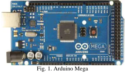
Arduino Mega is an electronic board and manufactured by Atmega. It can be universially programmed and it is an open source development platform. It uses a wiring language and it is easy to design electronics systems on it. It can easly interface to its electronic environment It can receive external signals from sensors and generates output signals to interface with the other devices. See Fig.1.
Arduino onboard hardware and pin connections can be controlled by external programming.Arduino Mega uses an
Atmega 2560 microcontroller and supports 5V and 3V working environment. According to microcontroller types Arduino types are defined. Programs which are written for one Arduino can be used with all Arduino types.
Advanced Arduino cards such as Megahas more than one Tx/ Rx pair. Hence these cards while communicating with other external modules they can also send data to computers around them. All onboardTx /Rx ports work synchronously. Since there are a few units such as GPS, GSM and GPRS which will synchronize with each other during the operations, Arduino Mega card is deployed in this study.[1]
Fig. 1. Arduino Mega
B.
GPS Click
Đt is a GPS device with an internal microcontroller called U blox Lea 6s. It supports microbus structure and works compatible with Arduino units. It uses an GPS antenna to receive GPS signals.[2] See Fig. 2.
Onboard TinyGPSPlus library is employed to communicate with Arduino unit. Received data is in NMEA format and it is parsed for futher operations[3].
Fig. 2. GPS Click
C.
GSM /GPRS Click
Copyright © 2016 IJECCE, All right reserved 45
International Journal of Electronics Communication and Computer Engineering Volume 7, Issue 1, ISSN (Online): 2249–071X, ISSN (Print): 2278–4209
GSM in machine to machine applications. There is a Telit GL 865 GSM moduleon the device. SIM card is placed together with this module on Modem. Other components on Modem are used for the correct operation of the module. There are ports on Modem for serial communication.Modem is used with a GSM Antenna [4]. See Fig. 3.
Fig. 3. GSM/GPRS Click
GSM/ GPRS Modem supports 850/900MHz Dual-band frequency range. It can be controlled with AT instructions. It does not have a suitable library to work with Arduino. Hence AT instructions are sent with Arduino programming through Arduino and communication is provided with the Modem. Every module on Modems has its own AT instruction set for operations.
D.
Click2Arduino
It is a pin compatible board with the Arduino platform. It has a microbus structure and it supports the devices with this microbus structure for operations.A Jumper system is employed to organize the pin connections. See Fig. 4.
Fig. 4. Click2Ardunio
E.
LCD Unit
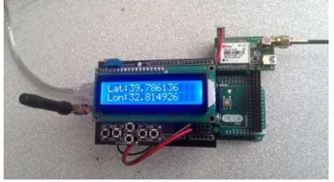
It is an electronic display unit with 2 horizantal lines and, 16 columns across the display area. Parced position information (longtitude and latitute) coming from GPS Click device is initialy displayed on this unit. See Fig. 5.
Fig. 5. LCD Unit
III.
PROCEDURES
A.
Hardware
System modules which are presented in section 2 are interconnected together on the hardware platform Arduino Mega board.Initially Click2Arduino card is mounted on Arduino Mega.GSMClick Modem is fixed on Click2Ardunio. Reset pin is set at off position.
Arduinopins 0and 1 are identified as RxandTx pins and they provide serial communication. These pins are also connected to USB line to provide communication with a computer.When they are connected to somewhere else, communication between Arduino board and computer seized to exist. Therefore, these pins are used to provide communication between computer and Arduino Mega board during sending instruction codes.
Serial communication with Arduino board can also be carried out with other electronic devices such as GPS CLICK. Txve Rx pins of GPS CLICK are cross connected with Arduino'sTxve Rx pins.
GPS CLĐCK device’s GPS TX pin is connected to RX1 19 pin and GPS RX pin to TX1 18 pin of Arduino Mega board. Additionally, GPS GND pin and supply pin are connected to GND pin and 5V pins of LCDdisplay unit.
GSM board connection with Arduino Mega board is provided bythe other pair of onboard Tx, Rxpins. "Software Serial” library of Arduino Mega is deployed during GSM communication with onboard Click2Arduino device.Hence, TX pin 3 and RX pin 10 of Arduino Mega board are connected to Click2Arduino pins of INT1 and PWM10. The connection between J10 and Reset (RST) pins on Arduino Mega board is cancelled to provide the connection between Click2Arduino and Arduino Mega board. See Fig. 6.
Fig. 6. GPS and GSM board connection on Arduino Mega board
Once GPS and GSM boards are placed on Arduino Mega and Click2Arduino boards; LCD display unit is mounted on top of the Click2Arduino board as shown in Fig. 5.
Copyright © 201
International Journal of Electronics Communication and Computer Engineering
Fig. 7. General view of the system Initially GSM connection settings are carried out the operations. Later on GPS device is started and GPS data is received every second.This data is
stored in variables. Finally GSM and GPRS settings are carried out and a connection is set up with a distant server through GPRS. GPS data is sent to the server every 10 seconds with GET commands. Sent data is recorded in a file in the server and displayed on a map. The operational flow chart is shown in Fig. 8.
B.
Software
Visual Studio program is deployed for the software development part. Arduino software devolopment media is set up on visual studio. Visual Studio is used to employ its Intellisense and Debug properties during developments General flow chart of the software program i
Fig.8.
Fig. 8. General flow chart of the systemoperation The communication between Arduino Mega board and other devices is set at the speed of 9600 Baud
arranged by the following program section; GSM_GPRSBaud= 9600;
GPSBaud= 9600;
mySerial.begin(GSM_GPRSBaud); Serial1.begin(GPSBaud);
Serial.begin(9600);
These instructions are used to start the communication between the computer and the Arduino Mega board.
Copyright © 2016 IJECCE, All right reserved 46
International Journal of Electronics Communication and Computer Engineering Volume 7, Issue 1, ISSN (Online): 2249–071X,
view of the system
Initially GSM connection settings are carried out during . Later on GPS device is started and GPS his data is parced and stored in variables. Finally GSM and GPRS settings are is set up with a distant server is sent to the server every 10 seconds with GET commands. Sent data is recorded in a file in the server and displayed on a map. The operational
program is deployed for the software development part. Arduino software devolopment media is set up on visual studio. Visual Studio is used to employ its
properties during developments. t of the software program is shown in
the systemoperation The communication between Arduino Mega board and
9600 Baud. This is arranged by the following program section;
These instructions are used to start the communication er and the Arduino Mega board.
Fig. 9. Software flow chart Once the communication is set up
settings are carried out. These setting are obtained by running the following functions in the order presented.
Delay function is introduced by using;
mySerial.println("AT"); delay(100);
Following instruction is used to read the data ShowSerialData();
Pin control is carried out by using the following program segment;
mySerial.println("AT&CPIN?"); delay(100);
ShowSerialData();
AT+CREG-command checks GSM registration status the following segment:
my Serial.println("AT+CGREG?"); delay(100);
ShowSerialData();
AT+CGATT
-
This GSM command issues a GPRS attach or detach.mySerial.println("AT+CGATT=1"); delay(100);
ShowSerialData();
AT+CGDCONT-This GSM
context parameters such as PDP type (IP, IPV6, PPP, X.25 etc), APN, data compression, header compression etc.
Once APNsettings are completed, user name and password instructions are requested by the following instruction sets
mySerial.println("AT+CGDCONT:1, delay(500);
ShowSerialData();
mySerial.println("AT#USERID= delay(100);
International Journal of Electronics Communication and Computer Engineering 071X, ISSN (Print): 2278–4209
Software flow chart of the system
communication is set up,GSM and GPRS settings are carried out. These setting are obtained by running the following functions in the order presented.
introduced to receive the return reply
Following instruction is used to read the data.
control is carried out by using the following program mySerial.println("AT&CPIN?");
checks GSM registration status with Serial.println("AT+CGREG?");
command issues a GPRS attach mySerial.println("AT+CGATT=1");
This GSM command sets the PDP context parameters such as PDP type (IP, IPV6, PPP, X.25 etc), APN, data compression, header compression etc.
settings are completed, user name and password instructions are requested by the following mySerial.println("AT+CGDCONT:1,\"IP\",\"internet\"");
Copyright © 201
International Journal of Electronics Communication and Computer Engineering
ShowSerialData();
mySerial.println("AT#PASSW=\"\""); delay(300);
ShowSerialData();
Data flow is provided by the following in
the communication is long, GSM module freezes. Hence these instructions must be deployed,
mySerial.println("AT&K0"); delay(100); ShowSerialData(); mySerial. println("AT&K=0"); delay(100); ShowSerialData();
GPRS device is connected and an IP is requested with the following segment;
mySerial.println("AT#GPRS=1"); ShowSerialData();
delay(1000);
Once IP is obtained, the device is connnected to a distance server. Server port address is taken as
mySerial.println("AT#SKTD=0,80,\"94.102.10.172 ShowSerialData();
delay(100); ShowSerialData();
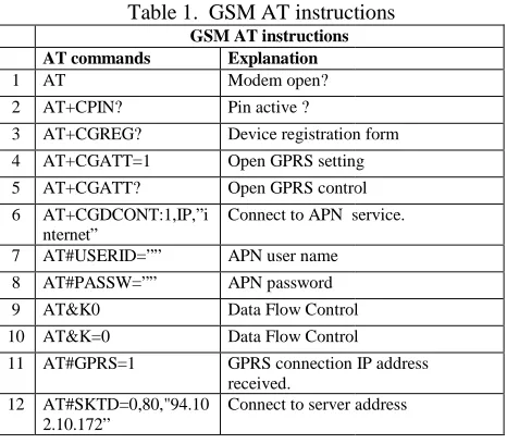
AT instructions for GSM connection are summarized in the following table1. These instructions are employed in the order presented to get the GSM connectio
Table 1. GSM AT instructions GSM AT instructions AT commands Explanation
1 AT Modem open?
2 AT+CPIN? Pin active ?
3 AT+CGREG? Device registration form
4 AT+CGATT=1 Open GPRS setting
5 AT+CGATT? Open GPRS control
6 AT+CGDCONT:1,IP,”i nternet”
Connect to APN service
7 AT#USERID=”” APN user name
8 AT#PASSW=”” APN password
9 AT&K0 Data Flow Control
10 AT&K=0 Data Flow Control
11 AT#GPRS=1 GPRS connection IP address received.
12 AT#SKTD=0,80,"94.10 2.10.172”
Connect to server ad
Once the GSM connection is realized, GPRS settings are carried out [5].TinyGPSPlus library is added. Received GPS NMEA data is parced and GPRS connection is waited [6].
When GPRS connection is realized and the device has a private IP address,it becomes ready to be connected to the server. Later on, AT#SKTD instruction generates a connection to a distant server.Connection can be verified with the CONNECTED reply.
Once all the connections are obtained, GET or POST methods with http properties are deployed to communicate position data. Longitute and lattitude values are sent every 10 seconds to show the position on the google map.
Copyright © 2016 IJECCE, All right reserved 47
International Journal of Electronics Communication and Computer Engineering Volume 7, Issue 1, ISSN (Online): 2249–071X,
Data flow is provided by the following instructions. If the communication is long, GSM module freezes. Hence
is requested with the
Once IP is obtained, the device is connnected to a distance server. Server port address is taken as 80;
"94.102.10.172\"");
AT instructions for GSM connection are summarized in the following table1. These instructions are employed in the order presented to get the GSM connection.
GSM AT instructions
Device registration form setting control
service.
Control Control connection IP address
address
connection is realized, GPRS settings are library is added. Received data is parced and GPRS connection is waited and the device has a it becomes ready to be connected to the instruction generates a connection to a distant server.Connection can be verified Once all the connections are obtained, GET or POST are deployed to communicate position data. Longitute and lattitude values are sent every 10 seconds to show the position on the google map.
GET instructions can be activated as follows sent every 10 seconds to generate
Host address and connection
continuity is provided with the following GET instructions. ShowSerialData();
mySerial.println("GET /dene.php?visor=false&latitude=" +lat+"&longitude="+lon+"&altitude= time+"&satellites="+satellites+"&speedOTG="+speed+"& course="+course+" HTTP/1.1"); mySerial.println("Host: 94.102.10.172"); mySerial.println("Connection: keep mySerial.println(""); mySerial.print(char(13)); mySerial.print(char(10)); mySerial.print(char(13)); mySerial.print(char(10)); lon = "";
lat = "";
Char (13) and Char(10) show the end of the GET instruction.
WAMP server is set up and using in to a file in the server. Google API
the position data on the google map.Map is updated every 5 seconds and newly added data is displayed as a map point [7][8]. Software architecture which is used by the server is shown in Fig. 10.
Fig. 10. Software architecture in the server.
An example position of the system on the google map is displayed in Fig. 11.
Fig. 11.
International Journal of Electronics Communication and Computer Engineering 071X, ISSN (Print): 2278–4209
ET instructions can be activated as follows. They are generate position coordinates. dress and connection must be continuous. This continuity is provided with the following GET instructions.
ne.php?visor=false&latitude=" "&altitude="+altitude+"&time"+ ="+satellites+"&speedOTG="+speed+"& HTTP/1.1"); mySerial.println("Host: 94.102.10.172"); mySerial.println("Connection: keep-alive");
show the end of the GET and using PHP, the data is placed Google API is used later to show google map.Map is updated every 5 seconds and newly added data is displayed as a map point . Software architecture which is used by the server is
Software architecture in the server. An example position of the system on the google map is
Copyright © 2016 IJECCE, All right reserved 48
International Journal of Electronics Communication and Computer Engineering Volume 7, Issue 1, ISSN (Online): 2249–071X, ISSN (Print): 2278–4209
The developed system can be deployed for the purpose of tracking objects on the map. The system is similar to to vehicle tracking system. Originality lies with the usage of Telit GL865with GPS+GSM+GPRS and Arduino Mega board which is a lower cost system compare to vehicle tracking system. A working program can be reached from the internet site
http://zeynepozdemir.net/dene.php
IV.
CONCLUSIONS
In this study, GPS data which is received on an Arduino Mega board are transfered to a server by using GSM and GPRS.
Since there is no GSM library compatible to the employed GPS device, AT instructions are deployed to set up the communication between GPS device and the server through GSM and GPRS.
Arduino is a embedded system where all the GPS, GSM devices are included in it. Since it is an embedded system, debug operations can not be done sufficiently. This wastes time in error correction situations.
Connection to server thorough GPRS is not as good as one expects due to the problems with the wireless transmission lines. By using an internet package GET instructions could be sent without any problems.
At a later stage the data received from the GPS device will be logged by using SD card shiled. Geofencing will be included to track the objects. Application will be developed in Android platforms for mobile platform.
V.
ACKNOWLEDGEMENTS
This study is financed by Ankara Üniversity BAP Office with Project number 13B4343013.
REFERENCES
[1] https://www.arduino.cc/en/Main/ArduinoBoardMega2560 [2] http://www.mikroe.com/click/gps/
[3] http://arduiniana.org/libraries/tinygpsplus/
[4] http://www.telit.com/products/product-service-selector/product-service-selector/show/product/gl865-dual/
[5] http://m2msupport.net/m2msupport/module-tester/ [6] http://www.gpsinformation.org/dale/nmea.html
[7] https://developers.google.com/maps/documentation/javascript/ [8]
https://www.cooking-hacks.com/documentation/tutorials/gprs-gsm-quadband-modulearduino-raspberry-pi-tutorial-sim-900/
AUTHOR'S PROFILE
Baki Koyuncuis a professor in computer eng dept of
Ankara university. He has received his BSc, Msc and PHD from Birmingham and Loughborough universities in United Kingdom. He is an IEEE senior member. He teaches computer hardware and software courses. His research areas are image processing, computer hardware, embedded systems, wireless sensor networks, RFIDs and GPS+GSM systems.
ZeynepÖzdemir is a final year student in Computer