33
Performance Comparison of a Helical Coil
Heat Exchanger with a Straight Tube Heat
Exchanger using Ansys-Fluent
Vishnu Prasad K
1, Ishnu Shaji
2, Nameer Ahmed
3and Vishnu Sivan
41, 2, 3, 4
Student, Mar Baselios Institute of Technology and Science, Nellimattom, Ernakulam
ABSTRACT
Heat exchangers are used in many industrial applications for heating and cooling purpose. This work focuses on the performance analysis of a tube in straight tube heat exchanger and helical heat exchanger for different flow configuration under variable operating conditions. The idea of an efficient heat exchanger is based on maximum heat transfer with minimum area required. The experimental investigation will be performed on helical heat exchangers with one and more number of turns and on straight tube heat exchanger set up with Computational Fluid Dynamics using FLUENT along with k-ε turbulence modelling scheme was implemented for the simulation study. The flow solution will be achieved by implementing k-ε turbulence modelling scheme.
Keywords: Helical coil, Heat exchanger, Fluid flow, Heat transfer coefficient
1. Introduction
The technology of heating and cooling of systems is one of the most basic areas of mechanical engineering. Wherever steam is used, or wherever hot or cold fluids are required we will find a heat exchanger. A heat exchanger is a device used to transfer heat between two or more fluids. Heat exchangers are used in both cooling and heating processes. The fluids may be separated by a solid wall to prevent mixing or they may be in direct contact. The double pipe heat exchanger has a pipe-in-pipe structure. They are widely used in space heating, refrigeration, air conditioning, power stations, chemical plants, petrochemical plants, petroleum refineries, natural-gas processing, sewage treatment, etc.
The objective of this work is to determine the heat transfer characteristics for a helical double-pipe heat exchangers by varying the flow rates of a single fluid in both the inner and outer tubes for counter flow and to compare the same with the double-pipe straight tube heat exchanger.And to create the Geometrical models of a helical coil heat exchanger and straight tube double pipe heat exchanger using Solid edge. The problem is defined and meshing is done in ANSYS FLUENT. It is used to predict the flow and temperature contours of both the heat exchangers and to compare the heat transfer characteristics of helical coil heat exchanger with straight tube heat exchanger.
2. Literature Review
i. Saud Ghani, Mohammed Rashwan, Muataz Ali
This paper experimentally investigates the usage of double-pipe condenser and evaporator in an air conditioning system. Deionized water (DIW) was used as the secondary heat transfer working fluid for both the evaporator and condenser units, and R-22 was used as the AC system refrigerant. Experimental results of the double-pipe heat evaporator or condenser setup showed a promising reduction in the compressor work and an increase in the system coefficient of performance (COP). The collected data showed that the system efficiency depends more on the evaporator DIW flow rate than on the condenser DIW flow rate. By increasing the DIW flow rate in the evaporator, the compressor work was shown to decrease, while the COP was shown to increase. In comparison with a standard rated air conditioning unit, using a double-pipe evaporator and condenser units with the maximum DIW flowrates resulted in a decrease of about 53% in the compressor work and a similar percentage of increase in the system COP.
ii. Timothy J. Rennie, Vijaya G.S. Raghavan
34 Nusselt numbers were calculated for the inner tube and the annulus. The inner Nusselt number was compared to the literature values. Though the boundary conditions were different, a reasonable comparison was found. The Nusselt number in the annulus was compared to the numerical data.
iii. Kolepaka Sridhar, K. Bicha
The flow pattern through a heat exchanger affects the required heat exchanger surface. A counter flow heat exchanger needs the lowest heat transfer surface area. It gives a higher value for log mean temperature difference than either a parallel flow heat exchanger or a cross flow heat exchanger. A heat exchanger can have several different flow patterns. Counter flow, parallel flow, and cross flow are common heat exchanger types. A counter flow heat exchanger is the most efficient flow pattern of the three. It leads to the lowest required heat exchanger surface area because the log mean temperature drop is the highest for a counter flow heat exchanger. In this thesis, analysis is done to compare the heat transfer rates between the two basic flow arrangements: (i) the unidirectional parallel flow (parallel flow or co-current flow), and (ii) bidirectional flow (counter flow or counter-current flow). CFD analysis and thermal analysis is done on the heat exchanger for different fluids, by taking hot water and refrigerants R134A, R22, R600A and different materials of heat exchangers. 3D models are done in Pro/Engineer and analysis is done in ANSYS.
3. Methodology 3.1 Modelling
Geometries for heat exchangers were created in Solid Edge ST4 as shown in figure 1, 2 and 3.Then it is exported as.Igs file to FLUENT14.5 for mesh generation.After generating mesh for both heat exchangers the meshed models are then exported to FLUENT14.5 for analysis.
Fig 1: Model of straight tube heat exchanger
Fig 2: Model of Helical tube heat exchanger 1
35 3.2 CFD Analysis
Computational Fluid Dynamics (CFD) is one of the branches of fluid mechanics that uses numerical methods and algorithms to solve and analyze problems that involve fluid flows. Computers are used perform the millions of calculations required to simulate the interaction of fluids and gases with the complex surfaces used in engineering. CFD predicts what will happen quantitatively when fluid flow, often with the complications of Simultaneous flow of heat
Mass transfer Phase change Chemical reaction Mechanical movement
Stress and displacement of immersed solids
3.3 Calculation of Heat Transfer Coefficients
The heat transfer coefficient was found by using the equation,
ℎ = 𝑄 𝐴. ∆𝑇 Q = Heat transfer (W),
H = Heat transfer coefficient (W/m2K), A = Area of heat transfer (m2),
ΔT = Difference between bulk average fluid temperature and average coil temperature (K),
Heat transfer coefficients were calculated for both the inner and outer tubes. For these calculations, average bulk temperatures were used
4. Model validation
The model was validated by comparing result of a double pipe helical heat exchanger modelled using the same software with that of literature of Timothy J. Rennieet al. The model consisted of a concentric heat exchanger (an inner coil surrounded by an outer coil).
Geometries for the heat exchanger were created in Solid edge ST4 and exported as.IGS for meshing. The dimensions are labelled in the figure 4 and the values are given in table 1. The heat exchanger had a length of 2π (one full revolution) and the pitch was 0.130m.
The analysis was done in fluent 14.5.The material used was iron r the coils and the fluid through the exchanger was water. A flow rate of 0.8 kg/s was given to both the fluids through inner coil and outer coil.
Fig 4: The labelled diagram of the crossection of the tube
Table 1:The dimensions of the double pipe
Characteristics Dimensions (in m)
Length of pipe 1
Inner pipe diameter 0.042
Outer pipe diameter 0.1
36 5. Results and Discussion
The heat transfer coefficient was found using the equation,
𝑄 ℎ =
𝐴. ∆𝑇
Where,Q = heat exchange (W), A = area of heat transfer (m2),∆𝑇 = difference between bulk average fluid temperature and average coil temperature (K), Heat transfer coefficients were calculated for both the inner tube and the outer tubes. For these calculations, average bulk temperatures were used.
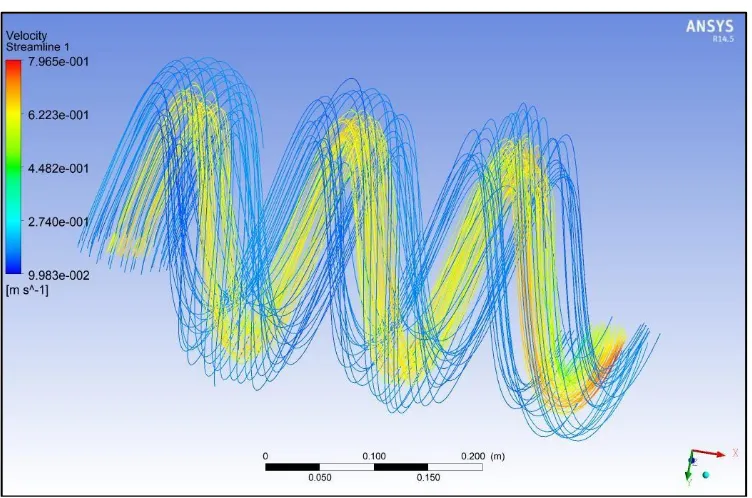
The figure 5 and figure 6 shows the temperature contour streamlines of helical tube heat exchanger 1 and 2 for various mass flow rates (i.e.,0.8, 1.1 and 2.1) at an inlet temperature of hot fluid 370K and cold fluid 280K.
Fig 5: The temperature contour streamlines of helical tube heat exchanger 1
37 The Figure 7 depicts the variation of heat transfer coefficient for both helical tube heat exchangers and the straight tube heat exchanger for various mass flow rates.
Fig 7:The variation of heat transfer coefficient of the three heat exchangers
6. Conclusions
Heat transfer characteristics of straight tube heat exchanger and helical tube heat exchangers with one and more number of turns are carried out using computational method. Results show that the heat transfer characteristics of the helical tube heat exchanger with more number of turns is much better than that of helical tube with lesser number turns. And the helical tube heat exchanger shows better heat transfer coefficient than that of straight tube heat exchanger, with remarkable increase in the heat transfer coefficient. From the simulations made, it is also found that the heat transfer coefficient decreases with increase in mass flow rate.
References
1. ShirgirelND, Vishwanath KumarP. Review on Comparative Study between Helical Coil and Straight Tube Heat Exchanger, IOSR Journal of Mechanical and Civil Engineering. 2013; 2:55-59.
2. WangTS, ChenYS. Unified Navier-Stokes flow field and performance analysis of liquid rocket engines,AIAA Journal. 1993; 9:678-685.
3. ShokouhmandH, SalimpourMRetal. Experimental investigation of shell and coiled tube heat exchangers using Wilson plots. 2007; 6:156-163.
4. Timothy JRennie, Vijaya GSRaghavan. Experimental studies of a double-pipe helical heat exchanger, Experimental Thermal and Fluid Science. 2005; 29:919-924.
5. Lin CX, EbadianMA. Developing turbulent convective heat transfer in helical pipes,International Journal of Heat and Mass Transfer.1997; 40:3861-3873.