Research Journal
Volume 11, Issue 3, September 2017, pages 48–55
DOI: 10.12913/22998624/70179 Research Article
APPLICATION OF SYSTEM MODELING AND THE SIMULATION
OF PHOTOVOLTAIC PRODUCTION
Raja Glaa1, Nafaa Jeddi1, Najeh Lakhoua1, Lilia El Amraoui1
1 Research Unit Signals and Mechatronic Systems, SMS, UR13ES49, National Engineering School of Carthage, ENICarthage, University of Carthage, Tunisia, e-mail: [email protected], [email protected], [email protected], [email protected]
ABSTRACT
The major goal of electric power companies is to give the quantity of electricity claimed by each consumer. This does not function without posing problems because consumption increases with time and the production will not be adequate to cope with the need for electricity. Besides, we may face environmental issues such as the in-crease of CO2 in the world, the conditions of producing energy, the difficulty of easily, quickly and economically storing large quantities of electricity. One of the solutions that could restrict and solve the problems is the production of renewable energy. In this paper, we focus on photovoltaic products; we present the photovoltaic conversion chain such as modeling, adaptation and control systems, as well as photovoltaic char-acteristics and system analysis methodology and planning of a photovoltaic system based on the OOPP method (Objectives Oriented Project Planning).
Keywords: photovoltaic systems, Maximum Power Point Tracking (MPPT), system-ic modelin, OOPP method.
INTRODUCTION
For hundreds of years, man has made enor-mous innovations that appeal to technological progress in all areas (electronics, automation, computer...) to improve living standards and make life easier. However, the progression of technology and the improvement of manual sys-tems to automated syssys-tems are a very important call to electricity.
That is why researchers are making great ef-forts to improve the production of electricity, switch between production and demand and as-sure monitoring and real time supervision of all environmental changes to the power grid by a very intelligent network called Smart-grid.
The smart grid contains seven areas, the most important is the production area, which is a large research area generally based on renewable sources such as water, wind and sun.
In this article, we will be interested in photo-voltaic generation for which a systemic model-ing method Objectives Oriented Project Plannmodel-ing (OOPP) is presented to give a good description of this system. This is how research on chain photovoltaic conversion and Matlab simulation on the characteristics of a photovoltaic module are presented.
CHAIN PHOTOVOLTAIC CONVERSION
A photovoltaic panel (PV) is used either to di-rectly operate a continuous load current, or con-nect to a public network, or both (Figure 1).
In this section, we identify the different
blocks of a photovoltaic conversion chain. We start by modeling a PV panel and then adapting the system by static converter DC-DC, along with ordering the system with the approach
perturba-tion and observaperturba-tion, and finally adapting the sys -tem using static conversion DC-AC.
Modeling of a photovoltaic module
Photovoltaic solar energy is the direct conversion of energy from photons into electricity. The combi-nation of several PV cells called module and the combicombi-nation of several modules form a PV panel [19, 21].
The cell of a PN junction photovoltaic submitted to the illumination can be schematized in Fig. 2 [22, 24]. The equivalent electric diagram of a PV cell can be modeled by equation (1):
pv ph d r
I =I −I −I (1)
Where: The photocurrent of the cell proportional to the sunning Es is given by equation (2):
( )
1000s
ph cc E
I =I (2)
The current through the diode is given by the equation (3):
(
( )
(e pv pv s 1)
q V I R
AKT
d sat
I I
+
= − (3)
The current derived from the shunt resistance is given by equation (4):
I
pv pv s
r
sh
V
R
I
R
+
=
(4)From equation (1), a simple methodology was developed to determine the characteristics of a cell or
photovoltaic panel, such as short-circuit current Icc and the open circuit voltage Voc to infer the implicit
mathematical expression of the current delivered by a photovoltaic cell, and its characteristic I-V. Similarly, for mathematical modeling of a PV panel, we must have the actual realization of the mod-ule structure, such as the inclusion of cells in a PV modmod-ule in the three following types [7, 10]:
• The cells are associated in series: The series connection of PV cells Ns delivers a voltage equal to the
sum of the individual voltages and a current equal to that of a single PV cell.
• The cells are associated in parallel: The parallel combination of the PV panels delivers a current
equal to the sum of the individual currents and a voltage equal to that of a single PV cell.
• The cells are associated in parallel and in series “mixed”, in order to increase the current and voltage.
• In general, the modeling of a PV panel is presented by equation (5) [12].
(5)
Adaptation system by the DC-DC converter
The converter is used to adapt the energy from the PV panel with load. In the case of a booster converter, the nature of the voltage does not change but the voltage level increases. In order to make the converter operate in a continuous conduction mode, the IGBT must be open and the current going through the inductor is not canceled (Figure 3) [1, 6].
GPV Panel
MPPT
Controler ConverterDC-AC DC Load
Grid
G
T
α
Ipv
Vpv ConverterDC-DC
GPV Panel
MPPT
Controler ConverterDC-AC DC Load
Grid
G
T
α
Ipv
Vpv ConverterDC-DC
Fig. 1. Blocks of photovoltaic conversion chain
Iph
D Rsh
Rs
Ipv
Vpv +
-Id Ir
Iph
D Rsh
Rs
Ipv
Vpv +
-Id Ir
In this case, the division of the output voltage of the chopper by its input voltage is equal to [4]:
1 1
out
pv
V
V = −
α
(6)With α: the duty cycle.
The nonlinear characteristic of the PV mod-ule and sensitivity to external conditions induces
energy losses hence the fluctuation of the output
voltage can damage the load. The importance of a control system is essential.
Ordering system with the approach perturbation and observation
Command systems that are mentioned later in systems analysis have the same purpose; it is the search of the maximum power point track-ing MPPT. However, the performance,
imple-mentation, complexity and rapidity will differ
from algorithm to another.
The photovoltaic panels are subjected to changing conditions in sunshine and temperature. These changes materialize the need of a power
extraction optimization algorithm that is chang-ing the values of voltage and current of the photo-voltaic generator to MPPT [5, 9].
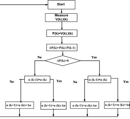
The algorithm studied in this research is the perturbation approach and observation that changed in a block diagram (Figure 4). The
com-mand offered by this approach obliges the oper -ating point of the photovoltaic generator to ap-proach the maximum power point and oscillate around it either by a linear positive or negative variation in voltage of the photovoltaic generator through time [25].
Adaptation system by converter DC-AC
The DC-AC converter is used to adapt the en-ergy from the PV panel either directly or by the intermediary of a Boost converter. This converter changes the nature of the continuous voltage to the alternative and stabilizes the voltage level after the PV panel. It can be a mono-phase for operating charges or three-phases for delivering energy to the grid (Figure 5) [8, 11].
SYSTEM MODELING OF PHOTOVOLTAIC
CONVERSION CHAIN
Analysis of a PV generator with system meth-od OOPP allows us to scale a PV system with a study that contains the best choice of components according to the charge and the installation site.
Presentation of method
The OOPP method is considered a commu-nication device, an analysis and project plan-ning, whatever its nature and its location [2, 3]. It is comprised of three essential stages: problem analysis stage; objective analysis stage and stage of activity planning.
ΔP(k)>0 Start Measure V(k),I(k) P(k)=V(k).I(k) ΔP(k)=P(k)-P(k-1)
α (k-1)>α (k) α (k-1)<α (k)
α (k+1)=α (k)+Δα α (k+1)=α (k)-Δα α (k+1)=α (k)-Δα α (k+1)=α (k)+Δα
No Yes Yes No Yes No ΔP(k)>0 Start Measure V(k),I(k) P(k)=V(k).I(k) ΔP(k)=P(k)-P(k-1)
α (k-1)>α (k) α (k-1)<α (k)
α (k+1)=α (k)+Δα α (k+1)=α (k)-Δα α (k+1)=α (k)-Δα α (k+1)=α (k)+Δα
No Yes
Yes No
Yes No
Fig. 4. Flow chart of P&O algorithm
PWM controler C1
K 1 K 2 K 3
K 4 K 5 K 6
Vbus /2
C’1 C2 C’2 C3 C’3
N O
Vbus /2
Vbus
Three phase Grid
PWM controler C1
K 1 K 2 K 3
K 4 K 5 K 6
Vbus /2
C’1 C2 C’2 C3 C’3
N O
Vbus /2
Vbus
Three phase Grid
Fig. 5. Three phase voltage inverter connected to a grid
L3
Rch Cout
Vpv Vout
Ipv Iout
D1
K R
ch Cout
Vpv Vout
Ipv Iout
D1
K L3
Rch Cout
Vpv Vout
Ipv Iout
D1
K
Workshop of problems analysis
Causal logic
Problems Tree
Objectives Tree Inversion
Fig. 6. OOPP method The problem analysis stage is very frequent
that the conception and implementation of a project meets a problematic situation expressed by a sponsor.
The approach used is Federative since it en-dorses the principle of organizing workshops bringing together a variety of competence domain. This is how the analysis of this situation must be conducted according to a structured methodology
based on causal logic identifying their effects and
causes (Figure 6) [13, 14, 15].
The objectives of the analysis process are presented by the Tree of problems constituting in a negative report. It allows a simple inversion (transform a negative state to a positive state) to build a Tree of Objectives which constitute the basis of any plan of Action [20, 23].
A causal logic of problem analysis, it is made logical to correspond “means-end” for developing the objectives tree. This is how we establish connections:
• Central Problem: PC → Global Objective: OG • Direct Cause: DC → Specific Objective: OS • Sub-Cause: SC → Result: R
• Sub-Sub Cause: SSC → Activity: A
To analyze an objective, a result, an activity or a derived activity, is arisen whenever we are confronted with the question: What is to be done to achieve the discussed objective or achieve the
result should we perform the identified activity?
The answer to this question is brought about by the decomposition of the level of analysis in the lower levels [16, 17].
The OOPP method allows, in addition to the
de-termination of the different steps in the analysis
of a project [18] from:
• Follow its evolution,
• Evaluate the project at its various stages,
• Identify dysfunctions and deviations between
performance and planning,
• Analyze the causes,
• Identify the responsibility.
Modeling of the photovoltaic conversion chain by OOPP method
With the smart grid, the production domain becomes very complex: Firstly, the consumer par-ticipates in the production of the electricity “Pro-sumers”. He can use his own production and if there is a higher production than its consumption, it will be sold or stored in a battery. Secondly, the unidirectional direction of the electrical network and the data information between the production
domain and the operation domain are modified
by a bidirectional direction. It is for this reason that we have chosen to analyze the PV production with the OOPP systemic method.
In this research, we use this method to study the production domain particularly the PV pro-duction, to manage its complexity, to evaluate the
system in these different stages and to determine the different applications.
Identification of PV production is the general
objective of system analysis (OG). This objective is presented in four tables; each one of them
iden-tifies a specific objective:
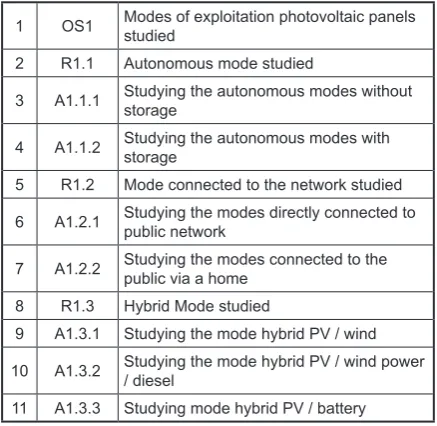
• OS1 to identify the modes of exploitation of
the PV panels.
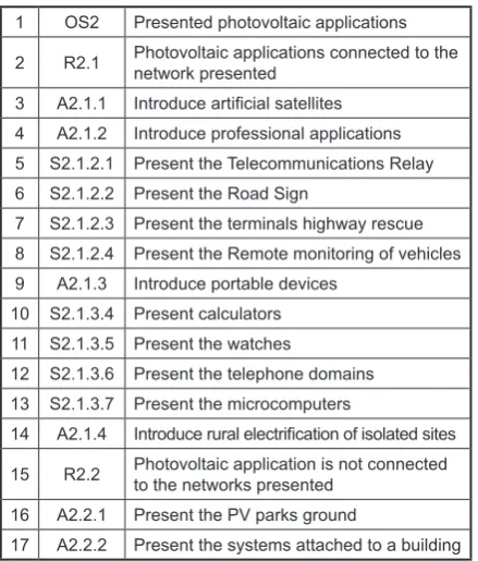
• OS2 to identify PV applications
• OS3 to identify the PV production cycle.
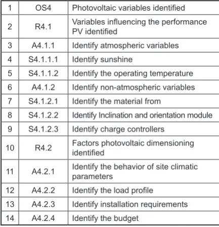
• OS4 to identify the variables of installation PV.
Table 1.Specific Objective OS1
1 OS1 Modes of exploitation photovoltaic panels studied
2 R1.1 Autonomous mode studied
3 A1.1.1 Studying the autonomous modes without storage
4 A1.1.2 Studying the autonomous modes with storage
5 R1.2 Mode connected to the network studied
6 A1.2.1 Studying the modes directly connected to public network
7 A1.2.2 Studying the modes connected to the public via a home
8 R1.3 Hybrid Mode studied
9 A1.3.1 Studying the mode hybrid PV / wind
10 A1.3.2 Studying the mode hybrid PV / wind power / diesel
SIMULATION RESULTS AND DISCUSSION
After modeling a photovoltaic panel by math-ematical equations (presented in section: Mod-eling of a photovoltaic module) and presenting systemic modeling, we present a simulation of the characteristics of a photovoltaic panel using the Matlab environment. The model study of PV module contains 36 cells connected in series.
As it was identified earlier in the OOPP analy
-sis, the photovoltaic efficiency influenced directly
by the atmospheric conditions (temperature and solar irradiation).
To see the performance of the system and the
influence of solar irradiation on the characteristics
of a PV module, we set the temperature value at 25°C and varied the value of the solar irradiation of 400 W/m² up to 1000 W/m². The result of this
variation (Figures 7 and 8) generates a significant
increase in the value of the short-circuit current and a small increase of the voltage value.
The influence of temperature variation in the
photovoltaic system characteristics (I-V and P-V) are presented in Fig. 9 and 10. In this case, we considered solar irradiation is constant at 1000
W/m2 and the temperature values are variables
between 10°C and 50°C.
When temperature increases values, we interpret that the voltage and the power of the system decreas-es slightly, but the current is almost constant. So, the
voltage is influenced directly by the temperature.
Table 3.Specific Objective OS3
1 OS3 Photovoltaic production cycle identified
2 R3.1 Transformation of solar radiation into electricity identified
3 A3.1.1 Identify the different photovoltaic cells 4 S3.1.1.1 Identify monocrystalline cells 5 S3.1.1.2 Identify polycrystalline cells 6 S3.1.1.3 Identify amorphous cells 7 A3.1.2 Modeling a photovoltaic cell
8 S3.1.2.1 Determining the characteristics of a photovoltaic cell
9 T3.1.2.1.1 Determine the short-circuit current 10 T3.1.2.1.2 Determine the open circuit voltage 11 T3.1.2.1.3 Determine the maximum power point 12 T3.1.2.1.4 Determine the maximum yield 13 T3.1.2.1.5 Determine the form factor
14 S3.1.2.2 Placing the cells depending on the load 15 T3.1.2.2.1 Grouping cells in parallel
16 T3.1.2.2.2 Grouping cells in series 17 T3.1.2.2.3 Grouping cells in series-parallel 18 S3.1.2.3 Model a photovoltaic panel
19 R3.2 Voltage regulation according the load used
20 A3.2.1 Use a DC-DC converter 21 S3.2.1.1 Using a boost converter 22 S3.2.1.2 Using a buck converter 23 S3.2.1.3 Using a buck-boost converter 24 A3.2.2 Use MPPT command
25 S3.2.2.1 Using perturbation and observation approach
26 S3.2.2.2 Using the approach of open circuit and short circuit
27 T3.2.2.2.1 Use algorithm based of measuring a fraction of the current Icc
28 T3.2.2.2.2 Use algorithm based of measuring a fraction of the voltage Voc
29 S3.2.2.3 Use incrementing the conductance approach
30 S3.2.2.4 Use artificial intelligence approach 31 T3.2.2.4.1 Using neural networks
32 T3.2.2.4.2 Using fuzzy logic 33 T3.2.2.4.3 Using genetic algorithms 34 A3.2.3 Use a DC-AC converter
35 A3.2.4 Connect the output voltage by the load 36 R3.3 PV plant monitored and supervised 37 A3.3.1 Install a sun sensor
38 A3.3.2 Install a temperature sensor 39 A3.3.3 Install a voltage sensor 40 A3.3.4 Install a current sensor 41 A3.3.5 Install a steering Pc 42 A3.3.6 Install an energy meter
Table 2. Specific Objective OS2
1 OS2 Presented photovoltaic applications
2 R2.1 Photovoltaic applications connected to the network presented
3 A2.1.1 Introduce artificial satellites 4 A2.1.2 Introduce professional applications 5 S2.1.2.1 Present the Telecommunications Relay 6 S2.1.2.2 Present the Road Sign
7 S2.1.2.3 Present the terminals highway rescue 8 S2.1.2.4 Present the Remote monitoring of vehicles 9 A2.1.3 Introduce portable devices
10 S2.1.3.4 Present calculators 11 S2.1.3.5 Present the watches
12 S2.1.3.6 Present the telephone domains 13 S2.1.3.7 Present the microcomputers
14 A2.1.4 Introduce rural electrification of isolated sites
15 R2.2 Photovoltaic application is not connected to the networks presented
16 A2.2.1 Present the PV parks ground
Table 4.Specific Objective OS4
1 OS4 Photovoltaic variables identified
2 R4.1 Variables influencing the performance PV identified
3 A4.1.1 Identify atmospheric variables 4 S4.1.1.1 Identify sunshine
5 S4.1.1.2 Identify the operating temperature 6 A4.1.2 Identify non-atmospheric variables 7 S4.1.2.1 Identify the material from
8 S4.1.2.2 Identify Inclination and orientation module 9 S4.1.2.3 Identify charge controllers
10 R4.2 Factors photovoltaic dimensioning identified
11 A4.2.1 Identify the behavior of site climatic parameters
12 A4.2.2 Identify the load profile
13 A4.2.3 Identify installation requirements 14 A4.2.4 Identify the budget
Fig. 7. Characteristics P-V with the variation of solar irradiation
Fig. 8. Characteristics I-V with the variation of solar irradiation
Fig. 9. Characteristic P-V with the temperature variation
Fig. 10. Characteristics I-V with the temperature variation
among researchers, to analyze and plan the
pho-tovoltaic system in different stages, to evolve the
system in its various steps, to study the installation site and to make the correct choice of components. On the other hand, a photovoltaic production chain is described with its various phases in its two modes. Thus, Matlab simulation allowed us to study the characteristics of a PV module under
optimum conditions and under different climate conditions such as the influence of solar radiation
and temperature values on the photovoltaic sys-tem characteristics.
In future work, we want to simulate all the photovoltaic production chains and systemati-cally model other renewable products, in order to have a production domain that is well developed and suitable for the smart grid.
CONCLUSION
Appendix
Symbol Description
α Duty Cycle A An ideal factor Cout Boost capacitor
Es The solar insolation in kW/m2
Iph Light-generated current or photocurrent Isat The cell saturation of dark current
Icc The cell short-circuits current at 25°C and 1kW/m2
Ipv PV current
Iout Boost output current
ISat cell’s reverse saturation current K A Boltzmann’s constant (1.38 ×10⁻²³J/K) L3 Input boosts inductance
q An electron charge (1.6 ×10⁻¹⁹C) Rsh A Shunt resistance
RS A series resistance of solar cell Rch The load
T The cell’s working temperature Vpv PV voltage
Vout Boost output Voltage
REFERENCES
1. Adil S., Arthur W. and Hanya A. simplified model -ing of a PV panel by us-ing PSIM and its compari-son with laboratory test results, Global Humanitar-ian Technology Conference, 2015.
2. AGCD. Manuel pour l’application de la Planifica
-tion des Interven-tions Par Objectifs (PIPO), 2ème
Edition, Bruxelles, 1991.
3. Annabi M. PIPO étendue : Méthode Inté-grée de Spécification, de Développement et d’Implémentation de Projet (MISDIP), Interna-tional conference on Sciences and Techniques of Automatic control and computer engineering STA’2003, Sousse, 2003.
4. Asma M., Ali H. and Oualid K. Modélisation et simulation d’un système PV intégré à un réseau BT par la méthode BU Watt-Var découple, 2014. 5. Bellia H., Yousef R. and Fatima M. A detailed
modeling of photovoltaic module using Matlab, Journal of Astronomy and Geophysics, 2014. 6. Boualem B., Abdelmadjid C., Jean-Paul G. and
Mabrouk H. système solaire photovoltaique connecté au réseau électrique et associé à un filtre actif parallèle, SGE’14, France 2014, 8-10. 7. Das B., Jamatia A. and Chak A. New Pertube and
its validation using data from PV module, IJAET, 4(1), 2012, 579-591.
8. Edouard M. and Donatien N. Mathematical modeling and digital simulation of PV solar
panel using Matlab software, International Jour-nal of Emerging Technology and Advanced En-gineering, 3(9), 2013.
9. Gwinyai D. Modeling of photovoltaic systems, Thesis, The Ohio State University, 2008.
10. Hanen A., Hafedh A., Kais L., Ahmad T. and Mo-hamed A. étude comparative de cinq algorithmes de commande MPPT pour un système photovol-taique, CIER’13, Tunis, 2013.
11. Jangwoo P., Hong-Geun K., Yongyum C. and Changsum S. Simple modeling and simulation of photovoltaic panels using Matlab/Simulink, Advanced Science and Technology Letters, 73, 2014, 147-155.
12. Kechar E., Azzag E. and Touaibia I. Influence des rayonnements solaires sur le rendement des panneaux photovoltaiques, International Journal of Scientific Engineering and Technology, 3(1), 2015, 71-77. 13. Killich S. and Luczak H. Support of
Interorganiza-tional Cooperation via TeamUp at Internet-Based Tool for Work Groups, Proceedings of the 6th internationally Scientific Conference, Berchtes -gaden, May 22-25, 2002.
14. Lakhoua M.N. and Ben Jouida T. Refining the objectives oriented project planning (OOPP) into method of informational analysis by objectives, In-ternational Journal of the Physical Sciences, 6(33), 2011, 7550-7556.
15. Lakhoua M.N. and Ben Jouida T. Refining the OOPP into Method of Representation of the In-formation by Objectives, International Trans-actions on Systems Science and Applications, 7(3), 2011, 295-303.
16. Lakhoua M.N. Systemic analysis of an industrial system: case study of a grain silo, Arabian Journal for Science and Engineering, 38, 2013, 1243–1254. 17. Lakhoua M.N., Jabri I., Battikh T., Maalej L.,
Mlouhi Y. Study on the use of Systemic Analy-sis and Image Processing Techniques in a Sports Meeting, European Journal of Scientific Research, 2015, 132(1), 2015.
18. Maalej L., Lakhoua M.N., Chakir I., Battikh T. and Jabri I. planning of a graphics on TV Project of an athletics event, CISTEM2014, Tunis 2014.
19. Ould Mohamed Yahya A., Ould Mohamed A. and Youm I. Etude et modélisation d’un générateur photovoltaique, Revue des energies renouvelables, 11(3), 2008.
20. Peffers K. and Ture Tunanen T. Planning for IS applications: a practical, information theoretical method and case study in mobile financial services, Information & Management, 42(3), 2005, 483-501. 21. Sahu T.P., Dixit T.V.and Kumar R. Perturb and
22. Stéphane P. Nouvelles architectures distribuées de gestio et de conversion de l’énergie pour les appli-cations photovoltaique, Thèse, Université de Tou-louse, Janvier 2009.
23. The Logical Framework Approach (LFA). Hand-book for objectives-oriented planning, Norad, Fourth edition, 1999.
24. Vechiu I. Modélisation et analyse de l’integration des energie renouvelables dans un réseau auto-nome, Thèse, Université du Havre, 2005.