103 Volume-4, Issue-1, February-2014,ISSN No.: 2250-0758
International Journal of Engineering and Management Research Available at
Page Number: 103-107
Study of Mitigation of Current Harmonics using Hysteresis Current Controller
Technique
Gopika Agarwal1, Shweta Gupta2
1
Student M-Tech, Electrical and Electronics Engineering Department, KIT, Rooma, Kanpur, Uttar Pradesh, INDIA
2
Assistant Professor, Electrical and Electronics Engineering Department, KIT, Rooma, Kanpur, Uttar Pradesh, INDIA
ABSTRACT
Power Quality problems are becoming most important issues for today’s power system engineers. Major use of power electronics appliances has increased the harmonics disturbances in power systems. The harmonics are basically due to presence of non-linear load in power system as these loads draw harmonic and reactive power components of current from main supply. Current Harmonics are generated by nonlinear loadsfor example drives of adjustable speed, static power supply, UPS etc. In order to reduce the effects of harmonics, a perfect compensator is required. Among many compensators Shunt Active Power Filters (SAPF) has better harmonics compensation. This paper deals with the performance analysis and study of SAPF under control strategy namely instantaneous real active and reactive power method (p-q) for extracting reference currents of SAPF under balance load condition. This paper includes the study and analysis of hysteresis control technique which is applied to compensate the current harmonics in power system.
Keywords: Power quality problems, Shunt Active Power Filter,
hysteresis current control techniques, p-q theory.
I.
INTRODUCTION
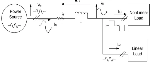
Due to fast growth in semiconductor industry, the use of power converters and power electronics devices is increasing day by day. But these devices are nonlinear in nature therefore they are also the main reason of power harmonics in power system. Figure 1 presents a layout of power system having source voltage VS , nonlinear load current iL1 contains
harmonics. The harmonics in the line current is generates a non-linear
voltage drop ∆V in the line impedance, which in turns distorts the load voltage VL. Due to distorted load voltage linear load current iL2
NonLinear Load
Linear Load Power
Source Vs
Is R
L
▲V
VL
IL1
IL2
also becomes non sinusoidal.
Fig. 1 Power System with nonlinear Load
The presence of Harmonics in power system is the basic reason of power losses in the distribution system, interference in the communication system and also the equipment failure. It also causes the operation failure of electronic equipment as they are very sensitive and work with very low energy levels. Because of these problems, end consumers are facing the power quality problems and also the voltage at different buses of power system will also get distorted.
On the other hand, the current distortion caused by the florescent lamp is related to the arc and the magnetic ballasts. Both currents of these devices are peaked and rich in third order harmonics. As for the power electronics devices, these loads control the flow of power by supplying the voltages and current drawn by the load is no longer sinusoidal but appears chopped or flattened [1]. Power quality problems are basically classified into two kinds: short term effects & long term effects.
The examples of short term effects are interferences, malfunctioning of equipments and devices.
The examples of long term effects are thermal losses, overheating and reduction of mean life time of capacitors, motors and transformers.
Initially the Passive filters were used as compensators to compensate the harmonic current problems, but they have some limitations like Background distortion can overload filter, interaction with distribution capacitor banks, system resonance problems, poor filtering characteristics, leading power factor, sensitive to capacitor switching. To overcome these limitations recent efforts have been done in the development of Active Filters. (Figure-2)
NonLinear Load
Linear Load Power
Source
Vs
R L
▲V
VL IL1
IL2 Is
Shunt Active Filter
Ifa
Fig. 2- Power system with non-linear load and a shunt active filter.
Active power filters which are more flexible and viable have become popular now days. The basic compensation principles of the active filter were proposed around 1970 by Bird, B.M. et al. in 1967 and Gyugyi, L. et al. in 1976. These active power filters are able to compensate harmonics continuously, regardless of the changing of the applied loads [2]. However, active power filters configurations are more complex and require appropriate control devices to operate. As there are various topologies of active power filter, researches are done in order to design and develop better control strategies and filter configurations [3],[4].
II.
POWER QUALITY PROBLEMS
Power quality refers to maintaining a near sinusoidal voltage to a bus at rated magnitude and frequency. In, addition the energy supplied to customer must be uninterrupted from supply point of view. It means the customer must get the pure sinusoidal supply with rated voltage and frequency interruption. If we don’t get the proper supply then there must be some problems. These problems are called power quality problems. These are listed are as follows:
Voltage Sag is defined as short duration ( 0.5 cycles to 1 min) decrease in supply voltage between 0.1pu and 0.9pu at rated power frequency. Faults are the main cause of its accurance. It causes accelerated aging, loss of data, instability and process interrupt.
Voltage Swell is defined as short duration ( 0.5 cycles to 1 min) increase in supply voltage between 1.1pu and 1.8pu at rated power frequency. Main causes of its accurance are switching off of large load or switching on of capacitor bank.
104
Voltage Imbalance is defined as a deviation in the magnitude or phase of one of more phases with respect to the magnitude of the other phases and the normal phase angle.
Transients is defined as undesirable momentary deviation of the supply voltage or load current. Its polarity may be additive or subtractive from the nominal waveform. The main causes are insulation breakdown or spark over, semiconductor device damage, shorts, accelerated aging, loss of data or stability.
Notchingis defined as steady state periodic phenomenon in which voltage disturbance is produced when power electronics devices are in operation. Three phase converters are the main cause for its accurance.
Voltage Flicker is defined as rapid change in supply voltage. It is caused by rapid variation in load current such as arc furnace.
Harmonicsis defined as steady state periodic phenomenon that produces continuous distortion in voltage and current waveform. Power electronics devices and nonlinear loads are the main cause of Harmonics.
Harmonics producing Loads are found in varied locations from offices to manufacturing plants and they are becoming inevitable in daily life. Various harmonic producing equipments are:
• Personal computers • Electronic lighting ballasts
• Variable and adjustable speed drives • Industrial process controls
• Electronic test equipment • Solid state controls • UPS systems • Medical equipments
• Electronic household appliances.
Harmonic currents can cause such problems as:
• Overheating or rerating of transformer • Overloading neutral conductors
• Excessive heating of wiring and connections • Damaging of capacitor banks
• Resonance
• Malfunction of electronic equipment • Communication interference • Distorted supply voltage • Increased power losses • Logic faults in digital devices • Errors in power metering
• Inadvertent thermal tripping of relays, circuit breakers and protective devices.
The most commonly used measure of the quality of a periodic waveform is the TotalHarmonic Distortion (THD). Current distortion factor is described as follows:
In above equation Vn is the magnitude of the nth harmonics voltage
and V1
Based upon the above theory table-1 shows the order of harmonics generated by nonlinear loads.
is the magnitude of the fundamental voltage.
Table-1 Load
/harmonic order
1 3 5 7 9 11 13 15
6 pulse rectifier
100 - 17 11 - 5 3 -
12 pulse rectifier
100 - 3 2 - 5 3 -
18 pulse rectifier
100 - 3 2 - 1 0.5 -
24 pulse rectifier
100 - 3 2 - 1 0.5 -
Electronic Computer
100 56 33 11 5 4 2 1
III.
ACTIVE FILTERS
Active filters are specially designed equipments which basically use power electronics equipments to compensate voltage or current harmonics or both simultaneously. These harmonics are basically originated by nonlinear loads.
Active Filters are classified into three categories: - Series type, shunt type and hybrid type.
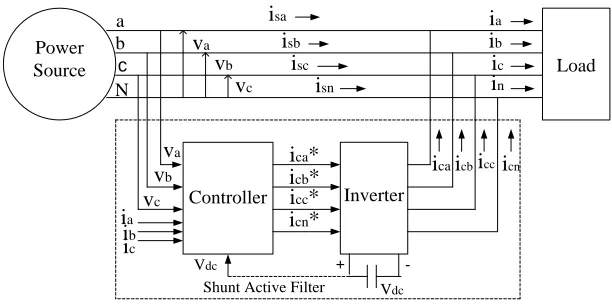
Figure 3 represents the schematic diagram of a shunt active filter for a three phase power system. SAPF in this can compensate current harmonics and can also perform power factor correction. It can also balance the unbalance load and eliminate the current in neutral wire. It contains the voltage source inverter with capacitor on DC side. The reference currents ( ica*, icb*, icc*, icn*) are calculated from the measured values of phase
voltages ( va, vb, vc) and the load currents ( ia, ib, ic). This reference current
are used by inverter to produce the compensation currents ( ica, icb, icc, icn
Power
Source Load
Controller Inverter
Shunt Active Filter
+ -Vdc Vdc a b c N va vb vc isa isb isc isn ia ib ic in ia ib ic va vb vc
icaicbicc icn
icb*
icc*
icn*
ica*
).
Fig. 3- Shunt Active Filter
Figure 4 represents the schematic diagram of a series active filter for a three phase power system. It is able to compensate the distortion in the power line voltages, by making the applied voltage sinusoidal. It consist of voltage source inverter and require three single phase transformers to interface with the power system. It does not compensate load current harmonics but it act as high-impedance for the current harmonics coming from the source side.
Power
Source Load
Controller Inverter
Series Active Filter
+ -Vdc Vdc a b c N vsa vsb vsc ia ib ic ia ib ic
vsc vcb*
vca*
vsb
vsa
vcc*
va vb vc vca vcb vcc
Fig. 3- Series Active Filter
There is one more solution to solve the load harmonics by using the combination of series and shunt active filter. This is shown in figure 5. These are known as hybrid type active filter.
105
IV.
SHUNT ACTIVE FILTER
The shunt Active filter is always connected in parallel to nonlinear load, which is used to cancel the reactive and harmonic currents from the nonlinear load, therefore the resulting current will be sinusoidal. In shunt active filter shown in figure 3 a current controlled voltage source inverter is used in order to generate the compensating current ic
A variety of methods are used for instantaneous current harmonics detection in active power filter such as FET ( Fast Fourier Technique ) technique, instantaneous p-q theory, synchronous d-q reference frame theory or by using suitable analog or digital electronic filters separating successive harmonics components[8]. This paper proposed the real and reactive power p-q theory.
* which is injected into the power source grid. This cancels all the harmonics components which are drawn by nonlinear load and keep the line current sinusoidal.
The main reason of the active filteris to compensate the current harmonics from harmonics producing loads. Along with that it is also use to compensate voltage harmonics and voltage imbalance. The basic principle of current harmonics compensation in shown in figure 6.
Fig. 6 - Basic principle of current harmonics compensation.
Harmonic current compensation using active filter is performed in a closed loop manner. The active filter injects the compensating current ic* to
the line in the power system. Thus the source current is equal to the load and filter current. This can be given by following equation:
V.
INSTANTANEOUS REAL AND REACTIVE
POWER THEORY
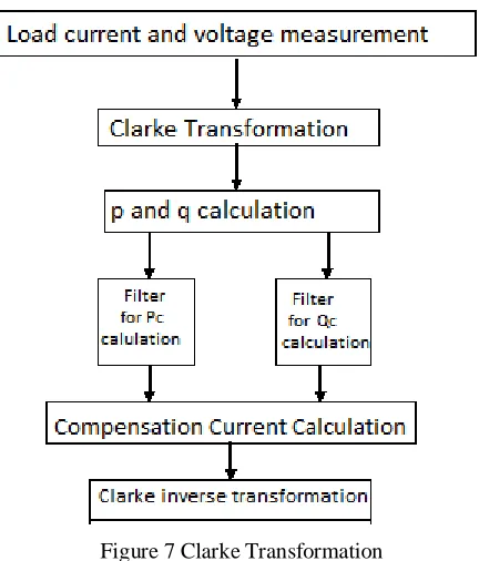
In 1983, Akagi et al. [1, 2] have proposed the “ The Generalized Theory of the Instantaneous Reactive Power in Three-Phase Circuits”, also known as instantaneous power theory, or p-q theory. This theory consists of Clarke transformation of the three-phase voltages and currents in the a-b-c coordinates to the α-β-0 coordinates, which is also followed by the calibration of the p-q theory instantaneous power components.
The Clarkes transformation is shown in figure 7 below:
Figure 7 Clarke Transformation
The space vectors which represent the relation of the transformation between each and every component of the basic 3-phase power system and the orthogonal coordinates are shown in terms of currents and voltages by the following equation 1, 2, 3 and 4:
=
………….. (1)
Or
=
……..…… (2)
As we know the that a-b-c are three phase mutually
orthogonal components, therefore as a result, the conventional
power for three phase circuits can be derived by usingthe
equations 1,2,3 & 4.
=
……..…… (3)
Or
=
……….… (4)
Therefore the instantaneous real power can be given by equation 5& 6:
p = v
ai
a+ v
bi
b +v
ci
c= v
……..…… (5)
o
i
o+ v
αi
α +v
βi
β……..…….. (6)
The three phase power is given by equation 7:
p
3¢= p + p
oFor balance supply three phase power is given by equation 8:
……..…… (7)
106
Therefore the instantaneous reactive power can be given by equation 9 & 10:
q = v
αi
β- v
βi
αq=
……..…… (9)
{i
a(v
c-v
b) + i
b(v
a-v
c) + i
c(v
b-v
c)
……..…… (10)
From these above equations, the instantaneous power is rewritten as shown in equation 11:
……..…… (11)
As the compensator can only compensate the reactive instantaneous power, therefore the real power is always set to zero. In order to cancel the reactive components in the line current the instantaneous reactive power is set into the opposite vectors. From equation 11, α-β current components are given by equation 12:
=
Therefore
=
……..…… (12)
Using the equation 12,real and reactive power can be identified from the below equations.
=
=
Therefore α and β axis real power components are as follows:
*p
*p
*p
*p
Similarly α and β axis reactive power components are as follows:
*q
*q
*q
*q
Therefore
The compensative reactive power can be identified deriving these equations. The compensating current of each phase is derived by using the inverse orthogonal transformations as shown below in equation 13
=
……..…… (13)
In this theory reactive power is detected on the base of instantaneous voltages and currents of the three phase circuits, that’s why we can say that this theorem performs instantaneously. Due to this the better harmonic compensation is provided.
For the fast response current controlled inverters, current control technique plays an important role. There are many types of current controllers such as hysteresis current , ramp type current control, predictive control etc.
VI.
HYSTERESIS CURRENT CONTROL
TECHNIQUE
Hysteresis band control is basically a feedback current control method, where the actual current continuously tracks the command current in the hysteresis band. In this method a reference sine wave current wave is compared with the actual phase current wave.
X y Ifref or
vfref
error
Gating signal
Active Power Filter Hysteresis Band Comparator
If or vf
Fig. 8 Hysteresis Current Control
This method is used to generate the pulses for voltage source inverter inbuilt in the Shunt active filter. This method controls the switches of the voltage source inverter asynchronously to ramp the current through the inductor up and down, so that it follows the reference current. Hysteresis current control is the easiest control method to implement in the real time. The working of this control technique depends upon the hysteresis band [8].
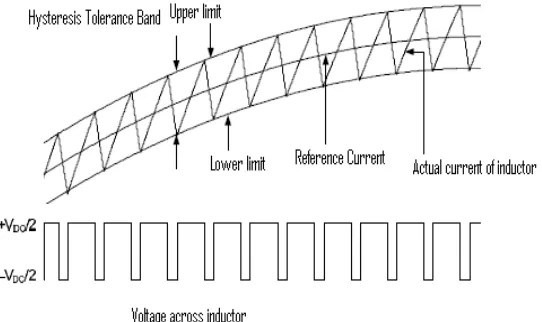
Figure 9 illustrates the ramping of the current between the two limits where the upper limit is the sum of reference current and the maximum error or the difference between the upper limit and the reference current and for the lower hysteresis limit; it is the subtraction of the reference current and the minimum error. Supposing the value for the minimum and maxi um error should be the same. As a result, the hysteresis bandwidth is equal to two times of error [7].
Fig. 9 Hysteresis Band and Generation of Pulses
When the current exceeds the upper limit of hysteresis band then the upper switch in the inverter bridge in turned off and lower switch is turned on, and the current starts decreasing. As the current crosses the lower band limit, the lower switch is turned off and upper switch is turned on.
107
Then due to this the inverter behaves like a current source current to be sinusoidal.
Analysis for the hysteresis current controller is as follows:
Where IV is the initial load current and tv is the starting time for TON.
t= T
At
ON, I=I
i.e. I
P
P = IV +
When the ripple current reaches the hysteresis top band upper switch is closed and lower is on. During Toff period the load current is:
Where tp is the initial time of Toff period. From the above mentioned
equation the Toff is given by:
=
Where (IP – IV
The total period is
)= DI (tolerance band)
T= Ton + Toff = + =
And the inverter switching frequency is:
For the constant tolerance band di, switching frequency depends upon the required output voltage, that is
EC = Emax
When output voltage is zero then the switching frequency will be maximum. This maximum frequency will be given by
Sin ώt
fm=
From the above equation it is clear that the variation in output voltage will also change the frequency. This method provide excellent dynamic properties and also easy to implement. There are some drawbacks which are as follows:
1.During the fundamental period, the resulting frequency changes which leads to irregular operation of the inverter.
2.When the zero voltage vector is applied, then the load is
disconnected at several instant over fundamental period of output voltage
VII.
CONCLUSION
The objective of this paper was to study and analyze the Hysteresis Current Control Technique briefly. Using this technique we are able to compensate the harmonics caused by three phase non linear loads. The instantaneous reactive and active theory is very much effective for Shunt Active Filter. By using Hysteresis current control technique harmonics are compensated to good extent.
REFERENCES
[1] Akagi.H, 1996. “New Trends in Active Filters for Power Conditioning”, IEEE Transaction on Industrial Applications, vol. 32, No 6, Dec., pp 1312-1322.
[2] Akagi.H, 2006. “Modern active filter and traditional passive filters”, Bulletin of the polish academy of sciences technical sciences vol.54.No.3 [3] Ali Ajami and Seyed Hossein Hosseini, 2006. “Implementation of a Novel Control Strategy for Shunt Active Filter”, ECTI Transactions on Electrical Eng., Electronics, and Communications Vol.4, No.1
[4] Akagi, Hirofumi. Active Filters for Power Conditioning. In Timothy L.Skvarenina. The Power Electronics Handbook: Industrial Electronics Series. United State of America: CRC Press. Chap. 17:30-63. 2002.
[5] Peng, F. Z., Akagi, H. and Nabae, A. A Novel Harmonics Power Filter.IEEE Transaction on Power Electronics Specialists Conference. April 11-14. PESC ’88 Record: IEEE. 1988. 1151-1159.
[6] Grady, W. M., Samotyi, M. J. and Noyola, A. H. Survey of Active Line Conditioning Methodologies. IEEE Transactions on Power Delivery.1990. 5 (3): 1536-1542.
[7] Bhattacharya S. and Divan D., “Synchronous frame based controller implementation for a hybrid series active filter system,” IEEE Conf. On Industry applications, vol.4, (1995):pp. 2531–2540
[8] M. Aziz, Vinod Kumar, Aasha Chauhan and Bharti Thakur, “Power Quality Improvement by Suppression of Current Harmonics Using Hysteresis Controller Technique.” International Journal of Recent Technology and Engineering (IJRTE) ISSN: 2277-3878, Volume-2, Issue-2, May 2013