Study of Supersonic Flow around Tandem
Cavities
Jayanta Sinha
#1, Neelakshi Kumar
*2, Aaradhya Kaul
$3#Amity Institute of Aerospace Engineering, Amity University Uttar Pradesh, India
Abstract
Two dimensional numerical simulations were conducted to investigate the supersonic flow around tandem cavities with front wall inclinations in both cavities and alternately inclining the front wall of each cavity at 90° and 120°. The unsteady simulations of the four models were conducted in ANSYS WORKBENCH using Reynolds Averaged Navier Stokes (RANS) equation with the k-ω turbulence model. Open cavities were considered with aspect ratio of the first cavity 3 and the second cavity 1. The Mach number was taken as 2 and Reynolds number as 4.5 x 10⁵. The cavities are characterised by unsteady flow due to the formation of vortices caused by shear layer interaction with cavity internal flow and formation of oblique shocks and expansion shocks. From the study it is observed that aft cavity flow behaviour is dependent on the fore cavity’s geometry. It is also observed that slightly different flow behaviour is also observed at the rear wall of fore cavity based on the aft cavity’s geometry. Introducing inclination in the wall of the cavities, reduces the peak pressure value at rear wall of the fore cavity but increases unsteadiness. A comparison of pressure oscillations and dominant frequencies has been studied for the models considered.
Keywords
—
Tandem cavities, supersonic flow; front wall inclinations;k-ω turbulence model;
shear layer interaction
I. INTRODUCTION
Cavity flows is a wide area of research due to its flow complexities, also it finds its application in high speed vehicles such as in weapon bays, landing gears, flame holding devices in scramjet and in analysis of multi row discs. Cavity is also formed as unavoidable result of deflection of flaps of the aircraft or in pipe fittings. Cavities also have lots of applications in flame holders for combustors due to their remarkable potential to stabilize the process of combustion without any major loss in total pressure. Hence, due to its widespread use and unavoidable presence it thus becomes very important to study the flow in it, so that, any kind of disturbance and resulting damages can be avoided. As it has been seen that cavities are usually present in tandem and also the supersonic flow creates the most complexities in these cavities therefore the subsequent paper deals with both these conditions. Supersonic flows in cavities are complex due to formation of vortices, shock waves, expansion
waves and also due to the separation and reattachment of flows. Highly unstable shear layer is formed along the cavities from its leading edge to trailing edge. Oscillations are therefore induced due to the collision of this shear layer which transmit sound waves and flow circulations. Cavity flow fields are characterised by L/D ratio, Mach number and Reynolds number. Based on their geometry cavities are classified as open, closed and transitional. Open cavities are short and have L/D <10 (fig.1), closed cavities have L/D>13and transitional type have L/D between 10 and 13. Based on research works it has been found that oscillations in closed cavities due to pressure variations are not much severe compared to the open cavity type. Therefore a wide range of research work has been done to study oscillations in open cavities and also on ways of controlling cavity flow which is done basically using either active or passive flow control methods.
Active
flow control needs some external devices for flow control. Examples of such devices are piezolectric flaps, voice-coil drivers, actuators, synthetic jets. While passive flow control is a simple, inexpensive technique in which no external object or modification is needed. Methods include modifying the geometry, introducing inclinations, adoption of vortexgenerators etc. Most of the research work till date is limited to a two dimensional single cavity flow analysis and flow control methods. A very few research work is done on two dimensional double cavities also known as tandem which have seen their application in flight vehicles. So it is important to study the effect of flow over second cavity due to first cavity and understand the oscillation formed and thus develop methods to control these flows. The work presented here deals with flow analysis in tandem cavities with front wall inclinations and their comparisons to understand the flow and also controlling the flow using passive flow control method as changes in the geometries have been brought.
Fig. 1 Flow over open cavity
Fig. 2 Tandem cavity model with l/d=3 for fore cavity and l/d=1 for aft cavity
NOMENCLATURE
P - Instantaneous Pressure P∞ - Free stream pressure
P/P∞ - Non- dimensionalised surface pressure
s/D - Non- dimensionalised wetted cavity length
L/D - Cavity Length to depth ratio C1F90 & C2F 90 - Model with front wall of fore cavity and aft cavity inclined at 90° C1F120 & C2F 120 - Model with front wall of fore cavity and aft cavity inclined at 120° C1F120 & C2F 90 - Model with front wall of fore cavity inclined at 120° and for aft cavity inclined at 90°
C1F90 & C2F 120 - Model with front wall of fore cavity inclined at 90° and for aft cavity inclined at 120°
Magnitude - Acoustic Pressure.
II. NUMERICAL MODELING
The numerical analysis of two dimensional supersonic flows over tandem cavities was
performed using CFD software ANSYS WORKBENCH. The model cavities had a depth of 4mm, 1st cavity L/D of 3 and 2nd cavity L/D of 1 and cavity interval S/D of 1. Four models were constructed with first model having 90° angle for both cavities (fig 3.(a)), 2nd model with front wall inclination of 120°for both cavities(fig 3.(b)), 3rd model with only front wall inclination for the first cavity at 120° (fig 3.(c)), 4th model with front wall inclination of 120° only for the second cavity((fig 3.(d)). Structured grid was generated with the grid number for upper zone in all models 400x150, for 1st cavity 120x80 and 2nd cavity 60x80 (fig 3.). Simulations in FLUENT used standard k-ω model with 2nd order implicit time.
A validation test was performed on a model cavity from Chel Hun Woo’s paper at Mach 1.5 and a good agreement was reached on the computation results. So structured mesh was generated for all the models which can be seen in fig. 3 using similar grids and the computational analysis was done using FLUENT at Mach 2.
To compare the numerical pressure oscillation frequency values with Rossiter frequency values, given semiempirical equation by Rossiter [4] is used:
Also the modified Rossiter formulation by Heller and Bliss [5] is used to calculate frequencies:
Where K and 𝛼 are experimental constants. K is a function of Mach number and equals to 0.55. The 𝛼 parameter is related to cavity geometry and has a value of 0.25. U∞ is free-stream velocity, M∞ is the
free-stream Mach number, St is the Strouhal number, and is the mode number of the cavity.
(b)
(c)
(d)
Fig. 3 Computational grid for the 2D models (a) C1F-90 & C2F-90; (b) C1F-120 & C2F-120; (c) C1F-120 & C2F-90; (d) C1F-120 & C2F-90.
III. RESULTSANDDISCUSSIONS
Computational analysis was performed to obtain a basic flow field around cavity with front cavity of L/D = 3 and second cavity L/D = 1 with front wall inclination of 90°. Unsteady analysis was performed in FLUENT for a flow time of 0.001.
The mach contours obtained for this model can be seen in( fig.4 a ) from which the formation of shear layer, vortices, shocks, flow separation and reattachment on the rear wall top corner for both cavities can be noticed . Pressure oscillations monitored at three different locations for both cavities can be seen in (fig.5 a) for fore cavity and (fig.5 b) for aft cavity it is thus noted that magnitude of pressure for the rear wall in both cavity cases is more than the base and front wall. Also highly unsteady shear layer formation can be seen for the aft cavity.
Fig. 4 Mach Contour (a) C1F-90 & C2F-90; (b) C1F-120 & C2F-120; (c) C1F-120 & C2F-90; (d) C1F-120 & C2F-90
(a)
(b)
Fig. 5 Pressure Oscillations at cavity front, base and rear walls for model C1F-90 & C2F-90 (a) Fore cavity; (b) Aft cavity.
(a)
(b)
Figure 6. Surface Pressure distribution for (a) Fore cavity; (b) Aft cavity
It can be noted that the rear wall for fore cavity is least for the model with both front walls of the cavities inclined at 120° and maximum for the cavities with front walls inclined at 90°. Further for cavity with C1F120 & C2F90 has a lesser pressure peak value at the rear wall of fore cavity than the C1F90 & C2F120 model. Incase of aft cavity rear wall, the model C1F90 & C2F90 has the least pressure peak value than all the other models, thus it can be noted that the introduction of inclination doesn’t have an aiding effect on the aft cavity’s peak pressure value and in turn has a greater pressure value which is not desirable.
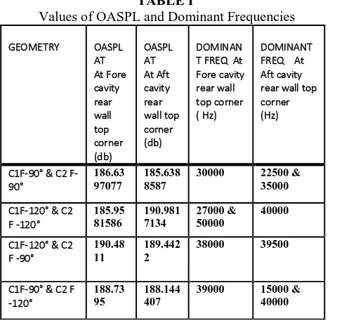
Graphs between acoustic pressure and dominant frequencies for rear wall top corner of both cavities are also plotted and shown in (fig. 7) for all the models and the dominant frequency has been jotted down in the table.1. It can be observed that the dominant frequencies for all models are above the normal hearing range for humans i.e. greater than 20kHz. That means the sound waves being created are ultrasonic which create high pressure oscillations and cause harm to the aircraft structure which thus needs to be controlled. In some cases two dominant frequencies can be observed which is due to two kinds of pressure amplitudes which occur alternately in two dimensional flow.
The OASPL values have also been tabulated for rear wall top corner for both cavities, and it can be thus concluded that the introduction of inclination of more than 90° increases turbulence and is not effective in controlling flow over tandem cavities. OASPL = 20 log10 [(∑Prms)/Pref] (dB)
Pref- 2x10⁻⁵ (N/m2)
Prms – root mean square of instantaneous pressure
(a)
(b)
TABLE I
Values of OASPL and Dominant Frequencies
IV.CONCLUSION
Computational analysis of two dimensional tandem cavities was carried out to understand the supersonic flow features in the cavities at Mach 2. Studies were done using same L/D ratios for all models but inclinations were introduced on the front wall and effect of these inclinations were observed and reported. Severe fluctuations were observed in the aft cavity front, base and rear walls as an effect of the presence of a preceding cavity. The control technique of introducing inclination of 120° at front wall was effective for controlling peak pressure and pressure fluctuations on rear wall of fore cavity but not very effective in reducing pressure values at the aft cavity rear wall for any combination of front wall inclination. Thus it can be said that for a single open cavity the front wall inclination is effective but for cavities in tandem it proves to be ineffective in controlling the flow for a succeeding cavity. Also high turbulence was observed for the cavities with inclinations of 120°. Also it can be noted that introducing inclination of 120° simultaneously on both cavities was still effective as the dominant frequency values noted were also less and the peak pressure in the front cavity was least but the other combinations prove to be ineffective and the flow field results are instead undesirable.
ACKNOWLEDGMENT(SIZE 10&BOLD) Author would like to thank the HOD and management of Amity University Uttar Pradesh for the support and resources provided during the tenure of this research work.
REFERENCES
[1] J Sinha, S Das, P Kumar and J K Prasad, “Computational Investigation Of Control Effectiveness On A Near Transition Open And Closed Axisymmetric Cavity” , 2014. [2] J Sinha, S Das, P Kumar and J K Prasad , “Studies On Axisymmetric Supersonic Cavity With Front Wall Inclination” , 2014.
[3] K.Mohri and R.Hilier, “Computational And Experimental Study Of Supersonic Flow Over An Axisymmetric Cavities”, 2011.
[4] J.E. Rossiter, “Wind Tunnel Experiments On The Flow Over A Rectangular Cavities At Subsonic And Transonic Speed”, 1964.
[5] Heller and Bliss, “The physical mechanism of flow-induced pressure fluctuations in cavities and concepts for their suppression”, 1975
[6] K.Krishanamurty, “Acoustic Radiation From Two Dimensional Rectangular Cut-Outs In Aerodynamic Surfaces” , 1955.
[7] V Sarohia, “Experimental Investigation Of Oscillations In Flows Over Shallow Cavities”, AIAA Journal, 15(7), 1977. [8] Chel Hun Woo, Jae Soo Kim, Kyung Hwang Lee, “Analysis Of Two Dimensional And Three Dimensional Supersonic Turbulence Flow Around Tandem Cavities” , 2006.
[9] Xin Zhang, John A. Edwards, “Experimental Investigation Of Supersonic Flow Over Two Cavities In Tandem” , 1992. [10] Selin Aradag, Hyung Jo Kim and Doyle D. Knight, “Two
And Three Diensional Simulations Of Supersonic Cavity Configurations”, 2010
[11] Chung-Jen Tam Paul D. Orkwis and Peter I. Disimile, “A Comparison Of Several Standard Turbulence Models For 2-D Open Cavity Flow Field Computations“, 1995 [12] V. Sridhar, S.L Gai and H. Kleine, “A Numerical
Investigation of Supersonic Cavity Flow at Mach 2”, 2012 [13] P. Nayyar, G. N. Barakos and K. J. Badcock, “Analysis
and Control of Weapon Bay Flows”, 2005
[14] Ö. H. Ünalmis, N. T. Clemens, and D. S. Dolling, “Cavity Oscillation Mechanisms in High-Speed Flows”, 2004 [15] Hongbo Wang, Mingbo Sun, Ning Qin, Haiyan Wu,
Zhenguo Wang, “Characteristics of Oscillations in Supersonic Open Cavity Flows”, 2012
[16] Kegerise, M.A., “An Experimental Investigation of Flow-Induced Cavity Oscillations”, 1999
[17] Stephen J. Lawson and George N. Barako, “Passive Control of Transonic Cavity Flow”, 2008
[18] N. Zhuang, F. S. Alvi, M. B. Alkislar, and C. Shih, ”Supersonic Cavity Flows and Their Control”, 2006 [19] 20. Zhang,X.and Edwards,J., “An Investigation Of
Supersonic Oscillatory Cavity flows Driven By Thick Shear Layers”, 1990
[20] D. Rockwell, E. Naudascher, “Review-Self-Sustaining Oscillations Of Flow Past Cavities”, 1978
GEOMETRY OASPL AT At Fore cavity rear wall top corner (db) OASPL AT At Aft cavity rear wall top corner (db) DOMINAN T FREQ At Fore cavity rear wall top corner ( Hz)
DOMINANT FREQ At Aft cavity rear wall top corner (Hz)
C190° & C2 F-90°
186.63 97077
185.638 8587
30000 22500 & 35000
C1F-120° & C2 F -120° 185.95 81586 190.981 7134 27000 & 50000 40000
C1F-120° & C2 F -90°
190.48 11
189.442 2
38000 39500
C1F-90° & C2 F -120°
188.73 95
188.144 407