Volume 2, Issue 10, October 2013
Page 198
ABSTRACT
In this, a four noded rectangular element with 5 degree of freedom (DOF) has been taken for the failure analysis of laminated composite beams. Apart from this the static and free vibration analysis of homogenous Timoshenko beam with two noded bar element having two DOF in each node with different boundary conditions are presented in MATLAB and compared with the results available in literature, and it is observed that the present results show the errors less than 1%. Natural frequency up to fifteen modes are compared for both Simply supported (SS) and Clamed- Clamed (CC) boundary conditions and also it is compared with different elements for two nodes, it has been found that with the increase of elements the present results are coming more closure to exact one.
Keywords: Simply supported (SS) and Clamed- Clamed (CC) boundary conditions, Finite Element Method (FEM)
1.
INTRODUCTION
Laminated composite beams are frequently used in the aerospace industries; therefore it is important to develop an efficient theory which accurately predicts the structural characteristics of laminated composite beams. When laminates are unsymmetrical stacked, bending stretching, coupling must be included in the analysis. Moreover, differences in elastic properties between fiber filaments and matrix materials lead to inplane-shear coupling. The performance of laminated composites in the fiber direction is outstanding, but bonding between different layers depends only on the matrix. The matrix, compared with fiber direction, limits the strength of laminated composites. However, composite structures subjected to low-velocity impacts or the drop of minor objects, such as tools during assembly or maintenance operation, exhibit a brittle behavior and can sustain significant damage. These impacts are particularly dangerous because they can drastically impair the mechanical behavior of the structure after impact with little or no visible damage.
To achieve better efficiency in terms of strength and weight-optimization, such structures are frequently appended with beam-like stiffener components.
As comparison with the analysis of laminated plates and shells, the work done so far in the area of fiber-reinforced composite beams is very limited. However, these structures have complicated failure mechanisms and modes compared to those of conventional metallic structures. One of the common failure modes is inter or intra-delamination.
The structural components like beam made of composite materials are being increasingly used in engineering applications. Because of their complex behavior in the analysis of such structures some technical aspects must be taken into consideration. The first and higher order shear deformation theories are improvements to classical theories. In these theories transverse shear deformation through the thickness of the structure is taken in to account.
Finite element method is versatile and efficient for the analysis of complex structural behavior of the composite laminated structures. The analysis of vibration and dynamics, buckling and post buckling, failure and damage analysis based on the various laminated plate theories is mainly carried out using Finite Element method.
The laminated beam theories are essential to provide accurate analysis of laminated composite beams, and a variety of laminated beam theories have been developed.
2. LITERATURE SURVEY
C. Santiuste et al. [42] Were compared Hou and Hashin criteria under dynamic conditions, analysing the failure of beams subjected to low-velocity impacts in a three point configuration. To accomplish this goal a progressive failure model was implemented in a finite element code to predict the failure modes (fibre tensile failure, fibre compressive failure, matrix cracking, matrix crushing, and delamination), considering both Hou and Hashin criteria.
Cardoso J.B., Valido A.J. [44] had presented a finite element model of analysis and sensitivity analysis that had been applied to several optimal design examples of cross-section properties of thin-walled laminated composite beams. The thin walled cross-sections were modeled as assemblies of flat symmetric laminated panels and their bending-torsion properties were expressed as integrals based on the cross-section geometry, on the warping functions for torsion, shear bending and shear warping, and on the properties of the corresponding laminate at each point.
Nguyen Quang-Huy, MohammedHjiaj, Guezouli Samy [45], had presented an exact finite element model for the linear static analysis of shear-deformable two-layer beams with interlayer slip. It was assumed that no uplift can occur. Both layers had, thus, the same transversal deflection but different rotations and curvatures. From the analytical expressions for
Failure Analysis of Laminated Composite
Beams by Finite Element Method
Chandramani Mishra
1, Nisheet Tiwari
2& S.P.S. Rajput
3Volume 2, Issue 10, October 2013
Page 199
be incorporated in any displacement-based F.E. code for the linear static analysis of two-layer beams with interlayer slip and arbitrary loading and support conditions.Chakravarty Uttam Kumar [46] had presented the reviews on the modeling of composite beam cross-sections. Theoretical models were available for simple composite beam cross-sections. But computational technique, such as finite element analysis (FEA), was considered for complex composite beam cross-sections. The available theoretical and computational tools for the modeling of composite beam cross-sections were presented in this paper.
3.
OBJECTIVES OF THE STUDY
1.Most of the authors analyzed the isotropic beams considering both first order and higher order shear deformation theory.
2.Parametric studies on lamination scheme are limited. 3.Free vibration analysis of the isotropic beams is abundant.
4.Free and forced vibration analysis of laminated composite beams is limited. 5.Failure analysis of the laminated composite beams is not done so far.
4.
MATHEMATICAL FORMULATION
The mathematical formulation for Element Stiffness Matrix given as follows: Element Stiffness Matrix
The displacement variables at any node r in the plate element are defined by:
= (1)
The displacements at any point on the middle plane within the beam element can be expressed in terms of the nodal displacements in the following form:
= (2)
Where [I5] is a 5×5 identity matrix and the Nr are the shape functions expressed in terms of the ξ-η coordinates of the beam element, Fig.1 the coordinates of the plate are expressed by:
x = (3) y = (4)
Where , are the coordinates of the node on the boundary of the beam in the x-y plane and are the corresponding cubic serendipity shape functions presented below.
The arbitrary shape of the whole beam is mapped into a Master beam of square region [-1, +1] in the s-t plane with the help of the relationship given by,
= , =1 = , =1
Where , are the coordinates of the ℎ node on the boundary of the plate in the x-y plane and , are the corresponding cubic serendipity shape functions presented below.
1 = ¼ ( − 1) (1 − ) ( + + 1) 2 = ½ (1 − ) (1 − 2)
3 = ¼ ( − 1) (1 + ) ( − + 1) 4 = ½ (1 − 2) (1 + )
5 = ¼ (1 + ) (1 + ) ( + − 1) 6 = ½ (1 + ) (1 − 2)
7 = ¼ (1 + ) (1 − ) ( − − 1) 8 = ½ (1 − 2) (1 − )
= 1 2 3 4 5 6 7 8
Volume 2, Issue 10, October 2013
Page 200
= ; [J] = and = ; [J] is the Jacobian matrix, is the inverse jacobian matrix.V is the volume.
= ; V = ℎ
Fig.1 Quadratic Isoparametric eight noded Element The element stiffness matrix of the plate is computed as:
[ =
[ = ξ η (5)
The stiffness matrix in Eqn. (4) is obtained by 2×2 Gaussian integration method. Here [D] is obtained by |J| is the determinant of the Jacobean matrix. The [B] matrix relates strain and displacement and is expressed by the derivative of shape functions. The generalized strain vector is given by:
= (6)
Where and are the transverse strain components obtained from Eqn. (6). The [B] matrix of Eqn. (7) can be expressed as:
(7)
And { = = [B] (8) The stress-strain relationship is written as
= [D] { } (9) Where [D] the rigidity matrix
Volume 2, Issue 10, October 2013
Page 201
(11)DXA = , DIA = × , = , = ×
= , = = × , = , = ×
= = × ℎ
E= modulus of elasticity, G=Shear modulus, = Poisson’s ratio, h=Thickness of beam
5.
RESULTS AND DISCUSSIONS
Examples have been worked out to validate the proposed approach. A number of examples have been presented and comparisons have been made with the results of earlier investigators wherever possible. The examples include isotropic and laminated composite beams with various boundary conditions. Two noded bar element with two degrees of freedom and eight- noded beam element is considered with five degrees of freedom per node.
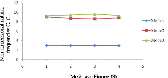
Example 1 Results for Central deflection and Non-dimensional Natural frequencies for Timoshenko beam clamped at both ends for different meshing (h/l=0.01) are shown in table 5.6 (a) & (b). Figure 2 shows Mesh size Vs Deflection and Figure 3 show Mesh size Vs Natural Frequency.
Table 1(a) Central deflection and (b) Non-dimensional Natural frequencies for a Timoshenko Beam clamped at both ends for different meshing (h/l=0.01)
Table (a)
Mesh size present
Result
Exact Result
10x1 0.0149578
0.015
20x2 0.014987
40x4 0.0149919
60x6 0.0149925
Table (b)
Mesh size v/s Non-dimensional Natural frequencies
Mesh size Mode 1 Mode 2 Mode 3
10x1 2.9974 9.0123 9.2333
20x2 2.9702 8.718 9.4322
40x4 2.96666 8.5720292 9.607289
60x6 2.96623 8.81063 9.29782
Volume 2, Issue 10, October 2013
Page 202
Mesh size Figure (3)Example 2 Results of comparison of central deflection of clamped beam at (h/l=0.001) and (h/l=0.1) for different mesh size with exact result are shown in Table 2.
Table 2 Central deflection of clamped (h/l=0.01) beam for different mesh size and lamination schemes.
Mesh size 0/30/30/0 0/60/60/0 0/90/90/0
10x1 0.0003110615232 0.00031106152314016 0.0003110798519916
20x2 0.00031224127445 0.00031224127425925 0.00031226006726
40x4 0.000312448831668 0.00031244883281275 0.0003124677093926
60x6 0.00031247789086 0.0003124778904503 0.000312496780296
6.
CONCLUSIONS
Based on the study following conclusions has been drawn:
1. Timoshenko beam (C.C. and S.S.) gives better results for non-dimensional natural frequencies when aspect ratios decrease.
2. Central deflection of clamped beam (h/l=0.01) is minimum for the lamination scheme of 0/30. 3. Ultimate strength of clamped beam (h/l=0.01) is maximum for the lamination scheme of 0/30.
References
[1] Zinenkiewicz OC, “Taylor RL. first ed. The finite element method”, vol. 1. Singapore: McGraw-Hill; 1989.
[2] Timoshenko SP. “On the correction for shear of differential equation for transverse vibration of prismatic bars” Phil’s Mag Ser 1921; 41:744–6.
[3] Timoshenko SP. “On the transverse vibration of bars of uniform cross-section” Phil’s Mag Ser 1922; 43:125–31. [4] Mindlin RD, Goodman LE. “Beam vibration with time-dependent boundary conditions” Trans ASME J Appl.Mech.
1950; 72:376–9.
[5] Hermann G. “Forced vibration of Timoshenko beams” Trans ASME J Appl. Mech 1955; 77:53–6.
[6] Anderson RA. “Flexural vibration of uniform beams according to the Timoshenko theory”, ASME, J Appl.Mech; 1951; 20; 504–510.
[7] Dalph CL. “On the Timoshenko theory of transverse beam vibrations”, Quart J. Appl. Math; 1954; 12; 175–187. [8] Cowper GR. “On the accuracy of Timoshenko’s beam theory”, ASME, J. Eng. Mech. Div. 1968; 94; 1447–1453. [9] Archer J. “Consistent matrix formulation for structural analysis using finite element techniques”, AIAAJ; 1965;
1910–1928.
[10] Davis R, Henshell RD, Wanburton GB. “A Timoshenko beam element. J Sound Vibrat”, 1972; 22; 475–487.
N o n -d im e n si o n a l n a tu ra l fr e q u e n c ie s C . C .
C e n tr a l d e fl e c ti o n
Volume 2, Issue 10, October 2013
Page 203
504–517.[12] Thomas DL, “Wilson JM, Wilson RR. Timoshenko beam finite elements”, J Sound Vibrat 1973; 31; 315–30. [13] Teh LS, “Hung CC. The vibration of beams of fibre reinforced material” J. Sound Vibrat 1977; 51; 467–473. [14] Dawe DJ. “A finite element for vibration analysis of Timonshenko beams”, J Sound Vibrat; 1978; 60; 11–20. [15] Kant T, “Gupta A. A finite element model for a high order shear deformable beam theory”, J Sound Vibrat; 1988;
125; 193–202.
[16] Lee KH, Senthilnathan NR, Lim SP, Chow ST. An improved zigzag model for the bending of laminated composite plates. Composite Structures; 1990; 15; 137–148.
[17] Chandrashekhara K, Krishnamurthy K, Roy S. “Free vibration of composite beams including rotary inertia and shear deformation”, Composite. Structures; 1990; 14; 269–279.
[18] Petyt M. “Introduction to finite element vibration analysis”, Cambridge University Press, Cambridge, 1990.
[19] KwonY.W. and Aygunes H. “Dynamic finite element analysis of laminated composit beamswith delamination cracks using contact impact conditions”, Compurers & Strucrures 1994; 58; 1161-1169.
[20] Wang S. “Free vibration analysis of skew fibre-reinforced composite laminates based on first order shear deformation plate theory”, Compurers & Strucrures; 1994; 63; 525-538.
[21] Marur S.R., Kant T. “Free vibration analysis of fibre reinforced composite beams using higher order theories and finite element modelling”, J Sound Vibrat 1996; 194; 337–351.
[22] Madabhusi-Raman Prabhu & F.Davalos Julio, “Static shear correction factor for laminated rectangular beams”,composites ; 1996; Part B 27B ; 285 -293.
[23] Wang C.M., Reddy J.N, and Lee K.H. “Shear deformable beams and plates”. Elsevier, Oxford, 2000.
[24] Lee Y.J,Lee C.H, Fu W.S. “Study on the compressive strength of laminated composite with through-the-width delamination ”, Composite Structures;1998; 41,229-241.
[25] Kameswara Rao M, Desai Y.M., Chitnis M.R., “Free vibrations of laminated beams using mixed theory”, composite structures; 2001; 52; 149-160.
[26] Subramanian P. “Flexural analysis of symmatric laminated composit beams by using element”, composite structures; 2001; 54; 121-126.
[27] Shimpi R.P.;Ghugal Y.M.; “A new layerwise trigonometric shear deformation theory for two-layered cross-ply beams”, Composites Science and Technology; 2001; 61; 1271–1283.
[28] Shimpi R.P. & Ainapure A.V. ,“A beam of finite element based on layer wise trigonometric shear deformation theory", composite structures; 2001; 53; 153-62.
[29] Lee J. and Schultz W.W. “Eigen value analysis of Timoshenko beams and axisymmetric mindlin plates by the pseudospectral method”, Journal of Sound and Vibration; 2004; 269(3–4); 609–621.
[30] Yu Wenbin “Mathematical construction of a Reissner–Mindlin plate theory for composite laminates”, International Journal of Solids and Structures; 2005 ; 42; 6680–6699.
[31] Subramanian P. “Dynamic analysis of laminated composite beams using higher order theories and finite elements”, Composite Structures; 2006; 73; 342–353
[32] Tahani Masoud, “Analysis of laminated composite beams using layerwise displacement theories”, Composite Structures ;2007; 79; 535–547.
[33] GoyalaVijay K., Kapania Rakesh K. “A shear-deformable beam element for the analysis of laminated composites”, Finite Elements in Analysis and Design; 2007; 43; 463 – 477.
[34] Mokos V.G. & Sapountzakis E.J., “A B.E.M Solution to transverse shear loading composite beams”, Computers and Structures; 2007; 85; 102–116.
[35] Sapountzakis E.J. & Mokos V.G. “A 3-d beam of composite cross-section including warping & shear deformation effects”, Computers and Structures; 2007; 85; 102–116.
[36] Jafari-Talookolaei R.A. and Ahmadian M.T. , “Free Vibration Analysis of a Cross-Ply Laminated Composite Beam on Pasternak Foundation”, Journal of Computer Science; 2007; 3 (1); 51-56.
[37] Sang-youl lee & dae-Youg Park, “Buckling analysis of laminated composite plates containing delaminations using the enhanced assumed strain solid element", Computers and Structures; 2007; 85; 102–116.
[38] Jun Li, Hongxing Hua, “Dynamic stiffness analysis of laminated composite beams using trigonometric shear deformation theory”, Composite Structures ; 2009; 89; 433–442.
[39] Lee Jaehong, Ahn Namshik & Phuong Vo Thuc ,“On six fold coupled vibrations of thin-walled composite box beams” ,Composite Structures ; 2008 ; 89 ;524–535.
[40] Aydogdu Metin, “A new shear deformation theory for laminated composite plates”, Composite Structures; 2008; 89; 94–101.
Volume 2, Issue 10, October 2013
Page 204
[42] Santiuste C., Sánchez-Sáez S., Barbero E., “A comparison of progressive-failure criteria in the prediction of thedynamic bending failure of composite laminated beams”, Composite Structures; 2010;92; 2406–2414
[43] Dash Anil Kumar “LARGE AMPLITUDE FREE VIBRATION ANALYSIS OF COMPOSITE PLATES BY FINITE ELEMENT METHOD”2010 thesis.
[44] Cardoso J.B., Valido A.J., “Cross-section optimal design of composite laminated thin-walled beams”, Computers and Structures; 2011; 89; 1069–1076.
[45] Nguyen Quang-Huy, MohammedHjiaj, Guezouli Samy, “Exact finite element model for shear-deformable two-layer beams with discrete shear connection” Finite Elements in Analysis and Design; 2011; 47; 718–727.