Geometry Optimization of Five-Phase Permanent Magnet
Synchronous Motors using Bees Algorithm
R. Ilka*, Y. Alinejad-Beromi*(C.A.) and H. Yaghobi*
Abstract: Among all types of electrical motors, Permanent Magnet Synchronous Motors (PMSMs) are reliable and efficient motors in industrial applications. Because of their superiority over other kinds of motors, they are replacing conventional electric motors. On the other hand, high-phase PMSMs are good candidates to be used in certain industrial and military projects such as electric vehicles, spacecrafts, naval systems and etc. In these cases, the motor has to be designed with minimum volume and high torque and efficiency. Design optimization can improve their features noticeably, thus reduce volume and enhance performance of motors. In this paper, a new method for optimum design of a five-phase surface-mounted permanent magnet synchronous motor is presented to achieve minimum Permanent Magnets (PMs) volume with an increased torque and efficiency. Design optimization is performed in search for optimum dimensions of the motor and its permanent magnets using Bees Algorithm (BA). The design optimization results in a motor with great improvement regarding the original motor which is compared with two well-known evolutionary algorithms i.e. GA and PSO. Finally, finite element method simulation is utilized to validate the accuracy of the design.
Keywords: Bees Algorithm (BA), Design Optimization, Finite Element Method (FEM), Permanent Magnets (PMs).
1 Introduction1
Permanent Magnet Synchronous Motors (PMSMs) are one of the most proper and efficient motors in electricity industry. Development of manufacturing technologies provides a situation where PMSMs can be economic with respect to conventional machines like induction and other traditional motors. Besides, these motors are good candidate for applications such as naval and space systems, electric vehicles and etc. Replacing excitation winding of rotor with Permanent Magnets (PMs) makes these motors more efficient than their excited counterparts; hence they are used in applications with high efficiency. The most important advantages of such motors are: high efficiency and power density, low loss, low maintenance cost, easy construction and etc [1-6].
One of the most interesting applications of PMSMs is to use as engine propeller of unmanned vehicles. Due to low space and limited capacity of batteries, having maximum efficiency and minimum volume is of great concern in such systems. Hence, design optimization
Iranian Journal of Electrical & Electronic Engineering 2015. Paper first received 15 Feb. 2015 and in revised form 05 Sep. 2015. * The Authors are with the faculty of Electrical and Computer Engineering, Semnan University, Semnan, Iran.
E-mails: [email protected], [email protected] and [email protected].
can enhance operational characteristics of motors. On the other side, these applications demand high reliability. In electrical motors, reliability increases with increase in number of phases in motor. High-phase motors are developed to obtain the highest possible reliability. In fact, in high-phase motors when one or two phases of motor are out of service due to failure, motor can continue to operate and overcome the fault [7-10].
There is great number of researches in literature dealing with optimum design of PMSMs. For example, in [11] authors presented a finite-Element based multi-objective optimization applied to interior PMSM. The optimization procedure is performed to design two IPMSM motors. Objective functions of this paper are reducing in weight and maximizing output power with wide constant-power region operation. In [12], design optimization of a permanent magnet synchronous motor was presented by artificial bee colony algorithm. Aim of the paper was to optimize the surface-mounted PMSM with geometrical variables and it the superiority of the proposed method was confirmed by comparison with Genetic Algorithm. In other research geometry optimization of PMSMs comparing full and fractional pitch winding configurations for aerospace actuation applications is presented [13] where the proposed
algorithm combines technical and physical advantages of the two mentioned configuration. Ref. [14] has presented an automated multi-objective design optimization for permanent magnet AC Machines with the help of finite element analysis and differential evolution in which a wide range of PM machines can be optimally designed. In [15] optimum design criteria for maximum torque and efficiency of a line-start PMSM is presented using response surface methodology and finite element method. Jannot et al. [16] have presented a multi-physic modeling of a high speed PMSM which is carried out with Genetic algorithm optimization where objective functions are efficiency and weight of motor. A design optimization of PMSM for high torque capability and low magnet volume has been presented in Ref. [17] where objective function is a combination of torque and magnet volume. Roshandel et al. [18] have proposed an optimization task for linear PMSM which is based on a reduction in thrust ripple. Design optimization for maximum torque and efficiency of a line-start PMSM is performed sing Response Surface Methodology and Finite Element Method [19]. Cogging torque minimization of surface-mounted PMSM is presented using Hybrid Magnet Shapes [20]. Design of outer-rotor PMSM for in-wheel electric drive train is carried out using Particle Swarm Optimization [21]. Optimal design of an interior PMSM is discussed by using a new Surrogate Assisted Multi-Objective Optimization [22]. Design optimization of a linear permanent magnet synchronous motor for extra low force pulsations is presented in Ref. [23]. PMSM with low torque ripple is designed [24] and PMSM with sinusoidal back EMF is designed by modifying its magnet shape [25]. In ref [26], different performance aspects of line-start PMSMs are discussed. Pole shape of PMSM is optimized by Reduced Basis Technique [27]. Control of PMSM drive is done with Neural Network [28]. High-efficiency PMSM is designed [29] and spoke-type PMSM is optimized combined design of experiments and differential evolution algorithms [30]. Optimization of PMSMs are performed and discussed by different evolutionary algorithms and different objective functions and optimization variables [31-35].
Aim of this paper is to optimally design a five-phase PMSM with surface-mounted magnet with the ratings of an engine propeller of an unmanned vehicle. For this purpose, Bees Algorithm (BA) is applied which is a novel optimization algorithm. In this Algorithm, the natural foraging behavior of honey bees is employed to find the optimal solution. Design optimization is performed with two types of objective functions which are combination of permanent magnets volume, torque and efficiency of the motor. It will be shown that, both types of optimization would reduce permanent magnets volume and in Type I, torque will be increased but efficiency will be decreased while in Type II efficiency will be increased but torque will be decreased. In next section, description of the PMSM is presented briefly.
In section 3, a brief description about Bees algorithm is given and optimization of the PMSM is discussed in section 4. After that in section 5, Finite Element Method (FEM) simulation is utilized to confirm the validity of the obtained results. Finally paper is concluded in section 6.
2 PMSM Description
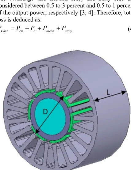
Fig. 1 shows a schematic view of a surface-mounted PMSM. As shown, Permanent Magnets (PMs) are placed on the surface of the rotor. In this condition, motor is non-salient (cylindrical rotor) and it has some good characteristics over other types of permanent magnets. In these cases, there is just one reactance. The inductive reactance of the armature of a non-salient-pole (cylindrical rotor) synchronous machine with the magnetic saturation included is
2
0
( )
20 ph w p
a
N k L
X f
P g
τ μ
π
=
′ (1)
where μ0 is the magnetic permeability of free space, τp is pole pitch, L is the axial length of the stator core [1-3].
Total copper loss is 2 5 ( )
cu s s
P = R I (2)
where Rs and Is are resistance and current of every phase, respectively. Core loss can be calculated as follow
2 2 2
c h m e m
P = k fB +k f B (3)
where kh and ke are hysteresis and eddy constants. Bm is maximum flux density and f is frequency. Mechanical loss (Windage and friction loss) and stray loss are considered between 0.5 to 3 percent and 0.5 to 1 percent of the output power, respectively [3, 4]. Therefore, total loss is deduced as:
Loss cu c mech stray
P =P +P +P +P (4)
Fig. 1 Typical surface-mounted PMSM.
Now, efficiency is determined through the following equation:
out
out loss P
P P
η=
+ (5)
Magnet volume is defined as follow
2 2
( ) ( )
2 2
M i m
D D
V =α π⎛⎜ −g −π − −g l ⎞⎟L
⎝ ⎠ (6)
where αi is pole arc to pole pitch ratio and D is stator inner diameter (or air gap diameter). Finally, electromagnetic torque is calculated as follow [5].
2
( )
2
av
D
T = πB L ac (7)
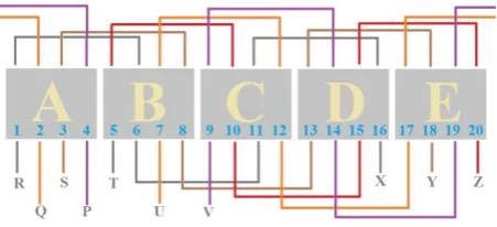
in which Bav is specific magnetic loading and ac is specific electric loading of the motor. ac is the number of ampere-turns of armature in unit length of armature in air gap [4]. Detailed view of motor and parameters are given in Fig. 2. Besides, Fig. 3 illustrates five-phase winding configuration of the motor. Appendix A gives parameters and dimensions of a sample PMSM which is designed traditionally as a criterion for comparison to the optimized motor.
3 Bees Algorithm
Bees Algorithm is an optimization algorithm inspired by the natural foraging behavior of honey bees to find the optimal solution. Fig. 4 shows the flowchart of the pseudo code for the algorithm in its simplest form.
Fig. 2 Dimensions and parameters of the motor
Fig. 3 Five-phase winding configuration.
Begin
(1) Initialize the solution population. (2) Evaluate the fitness of the population. (3) While (stopping criterion is not met)//Forming
new population.
(4) Select sites for neighborhood search. (5) Recruit bees for selected sites (more bees for the
best e sites) and evaluate fitnesses. (6) Select the fittest bee from each site. (7) Assign remaining bees to search randomly and
evaluate their fitnesses. End While
End
Fig. 4 Flowchart of the Pseudo code for optimization.
The algorithm requires a number of parameters to be set, namely: number of scout bees (n), number of sites selectedout of n visited sites (m), number of best sites out of m selected sites (e), number of bees recruited for beste sites (nep), number of bees recruited for the other (m-e) selected sites (nsp), initial size of patches (ngh) which includes site and its neighborhood and stopping criterion. The algorithm starts with the n scout bees being placed randomly in the search space. The fitnesses of the sites visited by the scout bees are evaluated in step 2.
In step 4, bees that have the highest fitnesses are chosen as “selected bees” and sites visited by them are chosen for neighborhood search. Then, in steps 5 and 6, the algorithm conducts searches in the neighborhood of the selected sites, assigning more bees to search near to the best e sites. The bees can be chosen directly according to the fitnesses associated with the sites they are visiting.
Alternatively, the fitness values are used to determine the probability of the bees being selected. Searches in the neighborhood of the best e sites which represent more promising solutions are made more detailed by recruiting more bees to follow them than the other selected bees. Together with scouting, this differential recruitment is a key operation of the Bees Algorithm.
However, in step 6, for each patch only the bee with the highest fitness will be selected to form the next bee population. In nature, there is no such a restriction. This restriction is introduced here to reduce the number of points to be explored. In step 7, the remaining bees in the population are assigned randomly around the search space scouting for new potential solutions. These steps are repeated until the stopping criterion which in this case is the iteration is met. At the end of each iteration, the colony will have two parts to its new population representatives from each selected patch and other scout bees assigned to conduct random searches [36-39].
It should be noted that in this survey, population size is considered 100, iteration 500 and elite number 40.
4 Design Optimization
It is of interest that we have a motor with least volume and cost while the motor has to fulfill operational characteristics. When the motor has least permanent magnets volume (while magnets providing enough flux density), cost of manufacturing will be decreased. Besides, motor should have higher efficiency and torque. This causes the motor to operate in the optimal point.
In this paper, two types of objective functions are considered. Objective functions are combination of volume of the permanent magnets, torque and efficiency of the motor.
4.1 Type I
Objective function of this part is defined as follow
( , , , )
( , )
m m i
V D L l
F
T D L
α
= (8)
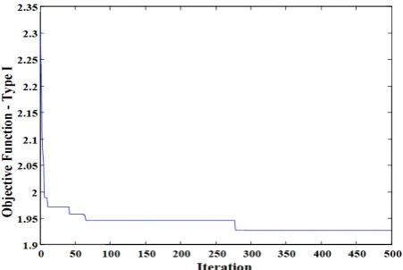
which has to be minimized. In fact, this means minimizing PMs volume while maximizing torque, simultaneously. By doing this, the total objective function is optimized (minimized). In this survey, design variables are: L, D, lm and αi. These four variables are selected because of the objective function definition and the requirements of the application. Maximum and minimum ranges of design variables are listed in Table 1. Among these four variables, D and L vary in discrete ways. lm and αi are continuous variables. After running optimization algorithm, optimum parameters are obtained. Fig. 5 shows objective function versus iteration. As shown in this figure, objective function converges and reaches to its optimal value i.e. 1.978 after 279 iterations.
The optimum values of the design variables are listed in Table 2.
Table 1 Minimum and maximum ranges of design variables.
Variable Min Max Step
D (mm) 60 100 1
L (mm) 50 90 1
lm (mm) 0.4 1 -
αi 0.65 0.9 -
Table 2 Optimal values of design variables for Type I.
Dimension/Parameter Value
D (mm) 73
L (mm) 61
lm (mm) 0.6
αi 0.78
Table 3 Specifications of typical and optimized motor for Type I.
Vm (cm3) T (Nm) η (%)
Typical motor 7.08 3.12 88.74
Optimized motor 6.33 3.37 88.57
Fig. 5 Objective function versus iteration for Type I.
Comparing these results with the specifications of the typical motor (presented in the Appendix A) shows that the design optimization results in magnets with decreased height but pole arc to pole pitch ratio slightly increased. Moreover, D has increased and L decreased.
Table 3 compares magnets volume, torque and efficiency of the two designs. It can be seen that the optimization reduces the magnets volume by 10.59% and increases the torque by 8.01%. Besides, it is shown that efficiency slightly decreased. However, this reduction in efficiency is not too important and it doesn’t affect the operational performance of motor.
4.2 Type II
Since in the previous definition of objective function, efficiency was decreased, in this part objective function is defined as follow
( , , , )
( , )
m m i
V D L l F
D L α η
= (9)
Again, this function means minimizing magnets volume while maximizing efficiency, simultaneously. The total objective function has to be minimized.
After running optimization algorithm, optimum parameters are obtained. Fig. 6 shows objective function versus iterations.
Fig. 6 Objective function versus iteration for Type II.
As shown, objective function converges and reaches to its optimal value i.e. 1.9263 after 246 iterations. The optimum values of the design variables are listed in Table 4. Again, the direction of variables variation is the same i.e. D and αi are increased while L and lm are decreased. However, there is a slight difference between the variables in Type I and Type II. Table 5 compares magnets volume, torque and efficiency of the two designs. As Type I, it is clear that the optimization reduces the PM volume by 20.6% but efficiency is increased just 0.4%. Moreover, it is shown that torque has decreased. In this case, reduction rate of magnets volume has almost doubled, but on the other side, efficiency has not increased too much.
Generally speaking, this optimization provides considerable advantages for the optimized motor over the typical one in terms of initial cost, volume and performance, because in both cases (Type I and II) permanent magnets volume was decreased and this reduction means reduction in cost of motor. Considering all aspects of this research, it is concluded that optimization should be performed based on the application of the motor. In other words, no optimization method can increase torque and efficiency in the same time and one of them has to be sacrificed.
4.3 Comparison with Other Algorithms
Now, Bees algorithm is compared with two well-known evolutionary algorithms i.e. Genetic Algorithm (GA) and Particle Swarm Optimization (PSO) algorithm in order to show the superiority of the proposed method. Table 6 and 7 illustrate the comparison of BA with GA and PSO for Type I and Type II, respectively. It is noted that, the weighting factors for the three algorithms are chosen identical to have a fair comparison. As shown in the Tables 6 and 7, BA has higher capability and fulfills the requirements of the optimization, because the fitnesses obtained by BA have much differences with respect to the typical design compared with GA and PSO. Besides, BA converges quicker and the reliability of the results is higher comparing to the GA and PSO algorithms.
Table 4 Optimal values of design variables for Type II.
Dimension/Parameter Value
D (mm) 68
L (mm) 62
lm (mm) 0.55
αi 0.8
Table 5 Specifications of typical and optimized motor for Type II.
Vm (cm3) T (Nm) η (%)
Typical motor 7.08 3.12 88.74
Optimized motor 5.62 2.97 89.12
Table 6 Comparison of BA with GA and PSO for Type I.
Vm
(cm3) T (Nm) η (%) Abs. Difference (%)
Typical Design
7.08 3.12 88.74 Vm T η
BA Design
6.33 3.37 88.57 10.59 8.01 0.019
GA Design
6.37 3.32 88.68 10.02 6.41 0.006
PSO
Design 6.42 3.35 88.61 9.32 7.37 0.014
Table 7 Comparison of BA with GA and PSO for Type II.
Vm
(cm3) T (Nm) η (%) Abs. Difference (%)
Typical Design
7.08 3.12 88.74 Vm T η
BA Design
5.62 2.97 89.12 20.62 4.8 0.42
GA Design
5.86 2.99 89.06 17.23 4.1 0.36
PSO
Design 5.95 3.03 89.04 15.96 2.8 0.33
Table 8 BH curve of material.
B [T] H [A/m] B [T] H [A/m]
0.0 0 1.6915 7957.7
0.2282 159.2 1.81075 15915.5
0.82215 318.3 1.92575 31831
1.0551 477.5 1.98375 47746.5
1.18355 636.6 2.0275 63662
1.2645 795.8 2.06175 79577.5
1.4251 1591.5 2.176 159155 1.5202 3183.1 2.38075 318310 1.59915 4774.6 2.48084 397887 1.65435 6366.2 3.48179 1193660
5 Finite Element Method Validation
The design optimization in this paper is totally based on analytical models of motor presented. Therefore, the accuracy of the electrical and magnetic models validates the design optimization. In this section, finite element method (FEM) is used for validation. Maxwell software which is based on FEM is one of the most important and efficient tools for this purpose.
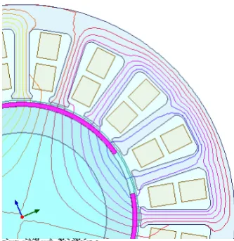
We give the software the dimensions obtained by optimization (Type I). A 2D FEM simulation is carried out and the numerical and graphical results are obtained. The effect of magnetic saturation was included in the FEM software by using H curves of the materials. B-H curves of this material of the stator and rotor steel are presented in Table 8. Fig. 7 shows finite element mesh of the motor. Fig. 8 shows flux lines diagram. Fig. 9 shows voltage and current of one phase of motor. As shown in Fig. 9, RMS value of phase voltage and phase
current is close to the rated values of motor. Also, moving torque of motor is shown in Fig. 10. This torque value has minimum deviation with the one obtained by analytical design.
Table 9 presents a comparison between results of analytical optimization and finite element method.
Fig. 7 Finite element mesh.
Fig. 8 Flux lines diagram.
Table 9 Comparison of analytical optimization and FEM results.
Results Analytical FEM Error (%)
Xa (Ω) 25.53 23.257 8.9
T (Nm) 3.37 3.186 5.4
Efficiency (%) 88.57 90.68 1.8
0.00 25.00 50.00 75.00 100.00 125.00 150.00 175.00 200.00 Time [ms]
-3.75 -1.75 0.25 2.25 4.25 6.25
C
u
rr
en
t(
P
h
as
eA
) [A
]
-250.00 -125.00 0.00 125.00 250.00
Vo
lt
ag
e(
P
h
as
eA)
[
V
]
Maxwell2DDesign1
XY Plot 2 ANSOFT
Curve Info
Current(PhaseA) Voltage(PhaseA)
Fig. 9 Voltage and current of one phase.
0.00 25.00 50.00 75.00 100.00 125.00 150.00 175.00 200.00 Time [ms]
-2.50 0.00 2.50 5.00 7.50 10.00
M
ovi
ng1
.T
or
que
[
N
ew
to
nM
et
er
]
Maxwell2DDesign2
Torque ANSOFT
Curve Info avg
Moving1.Torque Setup1 : Transient 3.1860
Fig. 10 Moving torque of motor.
6 Conclusion
This paper presented design optimization of five-phase surface-mounted permanent magnet synchronous motors. Design optimization is performed in search for proper dimensions of motor and its magnets. Two types of objective functions were introduced. In both of them, permanent magnets volume was major part and in both cases (Type I and II) permanent magnets volume was decreased. On the other hand, in Type I torque has increased but efficiency decreased while in Type II efficiency has increased but torque decreased. It is concluded that optimization has to be carried out based on the requirements of application. In other words, objective function is defined for a specific aim. For example, when a motor with least permanent magnets volume is required, the permanent magnets volume has to be included in the objective function and the optimization would concentrate on this objective. Besides, in practice, optimization would not improve all the performance characteristics of the motor (such as efficiency or torque) at the same time. In fact, there should be a trade-off between the output performances of the motor. After that, BA was compared with GA and PSO and superiority of BA was proved based on the results of fitnesses. Finally, finite element method confirmed the analytical optimal design with minimum error which proves the efficiency and accuracy of the design optimization.
Appendix
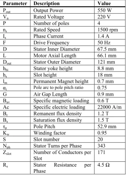
Table A1 Typical motor specifications used as a basis for comparison.
Parameter Description Value
Pout Output Power 550 W
Vn Rated Voltage 220 V
P Number of poles 4
ns Rated Speed 1500 rpm
Is Phase Current 1.4 A
F Drive Frequency 50 Hz
D Stator Inner Diameter 67.5 mm
L Motor Axial Length 66.1 mm
Dout Stator Outer Diameter 121 mm
hbi Stator yoke height 8.8 mm
hs Slot height 18 mm
lm Permanent Magnet height 0.7 mm
αi Pole arc to pole pitch ratio 0.75
G Air Gap Length 0.9 mm
Bav Specific magnetic loading 0.6 T
Ac Specific electric loading 22000 A/m
Br Remanent flux density 1.2 T
Bs Saturation flux density 1.5 T
τp Pole Pitch 52.9 mm
Kw Winding factor 0.95
S Slot number 20
Nph Stator Turns per Phase 343
Zslot Number of Conductors per
Slot
171
Rs Stator Resistance per
Phase
4.5 Ω
References
[1] D. C. Hanselman, Brushless permanent magnet
motor design, 2nd ed. Ohio 45036, Lebanon 3000
M Henkle Drive, Motorsoft Division of Fisher Electric Technology: Magna Physics Publishing, 2006.
[2] J. F. Gieras and M. Wing, Permanent Magnet
Motor Technology: Design and Applications, 2nd
ed., revised and expanded. NY l0016 New York, 270 Madison Avenue, Marcel Dekker, Inc: CRC Press, 2002.
[3] H. A. Toliyat and G. B. Kilman, Handbook of
Electric Motors, 2nd ed., revised and expanded.
FL 33487–2742, Boca Raton, Suite 300, 6000 Broken Sound Parkway NW, Taylor & Francis Group: CRC Press, 2004.
[4] E. S. Hamdi, Design of Small Electrical
Machines, New York, NY, USA: John Wiley &
Sons, Inc, 1994.
[5] J. Pyrhonen, T. Jokinen and V. Hrabovcova,
Design of Rotating Electrical Machines, The
Atrium, Southern Gate, Chichester, West Sussex, PO19 8SQ, United Kingdom: John Wiley & Sons Ltd., 2008.
[6] A. Emadi, Energy-Efficient Electric Motors, 3rd
ed., revised and expanded. Marcel Dekker, 270 Madison Avenue, New York, NY 10016, USA: CRC Press, 2004.
[7] L. Parsa, H. A. Toliyat and A. Goodarzi, “Five-Phase Interior Permanent-Magnet Motors With
Low Torque Pulsation”, IEEE Trans. Industry
Applications, Vol. 43, No. 1, pp. 40-46, 2007.
[8] S. Sadeghi and L. Parsa, “Multiobjective Design Optimization of Five-Phase Halbach Array
Permanent-Magnet Machine”, IEEE Trans.
Magnetics, Vol. 47, No. 6, pp. 1658-1666, 2011.
[9] P. Zheng, Y. Sui, J. Zhao, C. Tong, T. A. Lipo and A. Wang, “Investigation of a novel five-phase modular permanent-magnet in-wheel motor”, IEEE Trans. Magnetics, Vol. 47, No. 10,
pp. 4084-4087, 2011.
[10] S. Sadeghi, A. Mohammadpour and L. Parsa,
“Design optimization of a high performance five-phase slotless PMSM”, Int. Symposium on Power Electronics, Electrical Drives, Automation and Motion, pp. 18-20, June 2014.
[11] F. Parasiliti, M. Villani, S. Lucidi and F. Rinaldi, “Finite-Element-Based Multiobjective Design Optimization Procedure of Interior Permanent Magnet Synchronous Motors for Wide Constant-Power Region Operation”, IEEE Trans. Industrial Electronics, Vol. 59, No. 6, pp. 2503-2514, 2012.
[12] M. Mutluer and O. Bilgin, “An intelligent design optimization of a permanent magnet synchronous motor by artificial bee colony algorithm”,
Published online in Turkish Journal of Electrical Engineering & Computer Sciences, DOI:
10.3906/elk-1311-150, 2014.
[13] E. M. Tsampouris, M. E. Beniakar and A. G. Kladas, “Geometry Optimization of PMSMs Comparing Full and Fractional Pitch Winding Configurations for Aerospace Actuation Applications”, IEEE Trans. Magnetics, Vol. 48,
No. 2, pp. 943-946, 2012.
[14] G. Y. Sizov, P. Zhang, D. M. Ionel, N. A. Demerdash and M. Rosu, “Automated Multi-Objective Design Optimization of PM AC Machines Using Computationally Efficient FEA and Differential Evolution”, IEEE Trans. Industry Applications, Vol. 49, No. 5, pp. 2086-2096,
2013.
[15] B. H. Lee, H. P. Hong and J. H. Lee, “Optimum
Design Criteria for Maximum Torque and Efficiency of a Line-Start Permanent-Magnet Motor Using Response Surface Methodology and Finite Element Method”, IEEE Trans. Magnetics,
Vol. 48, No. 2, pp. 863-866, 2012.
[16] X. Jannot, J. Vannier, C. Marchand, M. Gabsi, J. Saint-Michel and D. Sa, “Multiphysic Modeling of a High-Speed Interior Permanent Magnet Synchronous Machine for a Multiobjective
Optimal Design”, IEEE Trans. Energy
Conversion, Vol. 26, No. 2, pp. 457-467, 2011.
[17] S. Vaez-Zadeh and A. R. Ghasemi, “Design
optimization of permanent magnet synchronous motors for high torque capability and low magnet volume”, Electric Power Systems Research, Vol.
74, No. 2, pp. 307–313, 2005.
[18] N. Roshandel Tavana and A. Shoulaie,
“Pole-shape optimization of permanent-magnet linear synchronous motor for reduction of thrust ripple”,
Energy Conversion and Management, Vol. 52,
No. 1, pp. 349-354, 2011.
[19] B. H. Lee, J. P. Hong and J. H. Lee, “Optimum
Design Criteria for Maximum Torque and Efficiency of a Line-Start Permanent-Magnet Motor Using Response Surface Methodology and Finite Element Method”, IEEE Trans. Magnetics,
Vol. 48, No. 2, pp. 863-866, 2012.
[20] L. Chikouche, B. Ladghem, K. Boughrara and R.
Ibtiouen, “Cogging Torque Minimization of Surface-Mounted Permanent Magnet Synchronous Machines Using Hybrid Magnet Shapes”, Progress in Electromagnetics Research B, Vol. 62, pp. 49-61, 2015.
[21] D. Wu, W. Fei, P. C. K. Luk and B. Xia, “Design Considerations of Outer-Rotor Permanent Magnet Synchronous Machines for In-Wheel Electric Drivetrain Using Particle Swarm Optimization”,
7th IET International Conference on Power Electronics, Machines and Drives, pp. 1-6, 2014.
[22] D-K. Lim, K-P. Yi, S-Y. Jung, J-S. Ro and H-K. Jung, “Optimal Design of an Interior Permanent Magnet Synchronous Motor by Using a New Surrogate Assisted Multi-Objective
Optimization”, IEEE Trans. Magnetics, Vol. 51,
No. 11, pp. 1-4, 2015.
[23] A. Hassanpour Isfahani and S. Vaez-Zadeh,
“Design optimization of a linear permanent magnet synchronous motor for extra low force
pulsations”, Energy Conversion and
Management, Vol. 48, No. 2, pp. 443-449, 2007.
[24] M. S. Islam, R. Islam and T. Sebastian,
“Experimental Verification of Design Techniques of Permanent-Magnet Synchronous Motors for
Low-Torque-Ripple Applications”, IEEE Trans.
Industry Applications, Vol. 47, No. 1, pp. 88-95,
2011.
[25] Y. Li, J. Xing, T. Wang and Y. Lu.
“Programmable Design of Magnet Shape for Permanent-Magnet Synchronous Motors With
Sinusoidal Back EMF Waveforms”, IEEE Trans.
Magnetics, Vol. 44, No. 9, pp. 2163-2167, 2008.
[26] A. Hassanpour Isfahani and S. Vaez-Zadeh, “Line start permanent magnet synchronous motors: Challenges and opportunities”, Energy, Vol. 34,
No. 11, pp. 1755–1763, 2009.
[27] A. Jabbari, M. Shakeri and S. Nabavi Niaki,
“Pole Shape Optimization of permanent magnet synchronous motors Using the Reduced Basis Technique”, Iranian Journal of Electrical and Electronic Engineering, Vol. 6, No. 1, pp. 48-55,
2010.
[28] C. H. Lin, “A novel hybrid recurrent wavelet
neural network control of permanent magnet synchronous motor drive for electric scooter”,
Turkish Journal of Electrical Engineering and Computer Sciences, Vol. 22, No. 1, pp.
1056-1075, 2014.
[29] N. Bianchi, S. Bolognani and P. Frare, “Design Criteria for High-Efficiency SPM Synchronous Motors”, IEEE Trans. Energy Conversion, Vol.
21, No. 2, pp. 396-404, 2006.
[30] P. Zhang, G. Y. Sizov, D. M. Ionel and N. A.
Demerdash, “Design optimization of spoke-type ferrite magnet machines by combined design of experiments and differential evolution algorithms”, IEEE Int. Electric Machines & Drives Conference, pp. 892-898, May 2013.
[31] C. Lucas, Z. Nasiri-Gheidari and F.
Tootoonchian, “Using Modular Pole for Multi-Objective Design Optimization of a Linear permanent magnet synchronous motor by Particle Swarm Optimization (PSO)”, Iranian Journal of Electrical and Electronic Engineering, Vol. 6,
No. 4, pp. 214-223, 2010.
[32] T. Senjyu, U. Urasaki, T. Kinjo, H. Sekine and T. Funabashi, “Parameter Measurement for Surface-Mounted Permanent Magnet Synchronous Motor Taking Stator Iron Loss into Account”, Electric Power Components and Systems, Vol. 33, No. 11,
pp. 1237-1251, 2005.
[33] M. Yang, L. Niu and D. Xu, “Antiwindup design for the speed loop PI controller of a PMSM servo
system”, Turkish Journal of Electrical
Engineering & Computer Sciences, Vol. 21, No.
5, pp. 1318-1327, 2013.
[34] R. Ilka, A. Roustaei Tilaki, H.
Asgharpour-Alamdari and R. Baghipour, “Design Optimization of Permanent Magnet-Brushless DC Motor using Elitist Genetic Algorithm with
Minimum loss and Maximum Power Density”,
Int. Journal of Mechatronics, Electrical and Computer Technology, Vol. 4, pp. 1169-1185,
2014.
[35] R. Ilka, S. A. Gholamian and S. Valiollahi,
“Optimum Design of a Permanent Magnet Brushless motor using Bees Algorithm and Finite
Element Analysis”, Intelligent Systems in
Electrical Engineering, Vol. 2, pp. 69-80, (in
Persian), 2012.
[36] D. T. Pham, A. Ghanbarzadeh, E. Koc, S. Otri, S. Rahim and M. Zaidi, “The bees algorithm–a novel tool for complex optimization problems”,
Proceedings of the 2nd Virtual International Conference on Intelligent Production Machines and Systems, pp. 3-14, July 2006.
[37] D. T. Pham, A. Ghanbarzadeh, E. Koc, S. Otri, S. Rahim and M. Zaidi, “The Bees Algorithm”,
Technical Note, Manufacturing Engineering Centre, Cardiff University, UK, 2005.
[38] D. T. Pham, A. A. Afify and E. Koç,
“Manufacturing cell formation using the Bees
Algorithm”, Proceedings of the Third
International Virtual Conference on Intelligent production machines and systems, July 2007.
[39] M. Alzaqebah and S. Abdullah, “The Bees
Algorithm for Examination Timetabling Problems”, Int. Journal of Soft Computing and Engineering, Vol. 1, No. 5, pp. 105-110, 2011.
Reza Ilka was born in Ghaemshahr, Iran, in 1988. He received B.Sc. and M.Sc. degree in power electrical engineering from Babol University of Technology, Iran in 2010 and 2012, respectively. He is currently pursuing his Ph.D. degree in power electrical engineering in Semnan University. His research interests include design and optimization of electrical machines.
Yousef Alinejad-Beromi was born in Damghan, Iran. He received the B.Sc. degree in electrical engineering from K.N.T. University, Tehran, Iran, and the M.Sc. and Ph.D. degrees from UWCC, Cardiff, U.K., in 1989 and 1992, respectively. He is currently an Associate Professor with the Faculty of Electrical and Computer Science Engineering, Semnan University, Semnan, Iran.
Hamid Yaghobi was born in Sari, Iran on 1978. He received his B.Sc. degree in Electrical Engineering from K.N.Toosi University of Technology in 2000, Tehran, Iran, M.Sc. degree in Electrical Engineering from Ferdowsi University in 2002, Mashhad, Iran and his Ph.D. in electric machinery from the Department of Electrical Engineering of Ferdowsi University, Mashhad, Iran in 2011. He is currently an Assistant Professor at Semnan University. His research interests are modeling and fault diagnosis, design and protection of electrical machines.