Please cite this article as: E. Avşar Aydin, Low-cost Vector Network Analyzer for Biomedical Applications, International Journal of Engineering (IJE), IJE TRANSACTIONS A: Basics Vol. 31, No. 4, (April 2018) 400-404
International Journal of Engineering
J o u r n a l H o m e p a g e : w w w . i j e . i rLow-cost Vector Network Analyzer for Biomedical Applications
E. Avşar Aydin*
Adana Alparslan Türkeş Science and Technology University, Department of Aerospace Engineering, Sarıçam, Adana, Turkey
P A P E R I N F O
Paper history:
Received 15 January 2019
Received in revised form 01 February 2019 Accepted 07 March 2019
Keywords:
Reflection Coefficient Standing Wave Ratio Low-Cost Vector Network Microstrip Antenns Ultra Wideband
A B S T R A C T
A low-cost and portable vector network analyzer (VNA) which covered operating frequency between 1MHz to 3GHz is used for vector reflection coefficient and standing wave ratio (swr) of the various microstrip antennas. T his paper presents measurements of various ultra wideband (uwb) microstrip antennas for applications in biomedical field. Selection of antenna is an important key for detection of different situations in biological signals. Measurements of antennas were performed by using miniVNA T iny which operates by radiating an electromagnetic wave through an antenna and measuring standing wave ratio (swr) and return loss. However, the miniVNA T iny is low-cost components and easy-to-produce antennas. The results indicate the good performance for UWB systems, especially microwave medical imaging applications. However, this device may enable for a low cost stepped-frequency system for use in tissue spectroscopy, field monitoring, and potentially in breast tumor detection.
doi: 10.5829/ije.2019.32.03c.07
1. INTRODUCTION1
The idea that microstrip structures are radiating elements that could be used as antennas which was first proposed by Deschamps in 1953 [1]. Although the first patent on this subject was published in France in 1955 by Gutton and Baissinot [2]. A practical antenna has not been produced for about 20 years. The main reason was the absence of good dielectric bases. With the development of low-loss, mechanically and thermally compatible dielectric base materials, the first microstrip antenna design was made by Munson [3] and Howell [4] at the beginning of 1970's. These antennas were designed to be thin and surface-compatible, and were used in space shuttles and cosmetics. Many research articles have been discussed to improve the design of microstrip antennas since these designs have advantages such as easy and low cost production of microstrip antennas, low volume coatings and dual frequency characteristics. Studies conducted by Bahl, Bhartia, James, Hall and Wood and many researches also conducted by Dubost were still preserved and have been used today [5, 6]. A number of research findings have been made of research breaks and out-of-standards, so in 1979 the first international
*Corresponding Author Email: rasvaenim [email protected] (E. Avşar Aydin)
meeting was held at New Mexico State University to discuss about the material, design and theories of microstrip antennas [7]. After all these stages, the use of microstrip antennas increased since 1970. In the 1980's , important researches as well as the practical implementation of microstrip antennas and the fabrication of microstrip antennas were established [8, 9]. Microstrip antennas are now being used extensively in electronic devices and information transmission due to their small size and high frequency supporting structures, as well as their ease of manufacture and use [10-12].
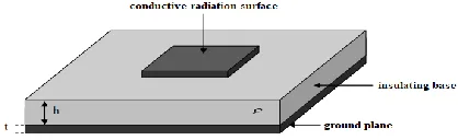
The general structure of microstrip antennas is as shown in Figure 1, insulator, it consists of a thin base material, a conductive radiation on a surface of this material and a conductive soil layer.
Figure 1. General structure of microstrip antenna
The dimensions and shape of the radiation element, the thickness of the base material and the dielectric constant are the main parameters directly affecting the electrical performance of the stationary antenna. In addition, the base material is used to mount the circuit elements appropriately and they support these elements mechanically. Microstrip antennas have values of 50-200 μm as the thickness of metallic elements used in radiation and soil surfaces is t << λo (free space wave length). Copper is usually used as the metal and it is adhered to the dielectric base material by chemical routes. The dielectric base is an insulating material that is optionally selected. The dielectric constant of the base material is between 2.2 and 12, and the thickness (h) is between 0.003λo and 0.05λo. Materials such as alumina, quartz, polytetrafluoroethylene (PTFE) are used as the dielectric base material. However, since these materials are expensive, and are used at high frequencies to facilitate integration with integrated circuits, FR-4 material is often used. The low dielectric constant of the base materia l improves the radiant performance of the antenna by increasing the effect of the fringe fields. In this case, however, a larger radiating element must be used to obtain the same frequency response, and the physical dimensions of the antenna increase [5]. If the dielectric value of the base material is small and the thickness is large, the coil is provided with the ideal radiation and the frequency bandwidth is also increased [13-15]. However, increasing the thickness of the base material can trigger the formation of surface waves, resulting in reduced antenna efficiency and impaired antenna radiation pattern. The electrical properties of the dielectric bases are determined by dielectric constant and loss tangent.
The microstrip UWB antennas have considerable attention for biomedical applications (e.g. breast cancer detection, brain cancer detection, health monitoring, etc.) due to their mannumber of advantages such as low cost, non-ionizing, low health risk, good detection of tumors, and ease of production. In this study, three different UWB microstrip antenna (as shown in Figure 2) measurements were performed using a mini Vector Network Analyzer (VNA) and the results were evaluated.
2. EXPERIMENTAL SETUP
The websites of large VNA manufacturers, such as Agilent, Rohde and Schwarz [15], show a wide variety of VNA equipment available. For the most sophisticated users, VNAs can provide high accuracy signal measurements over a wide frequency range. This can usually justify the use of GPRs and well-defined areas that foresee very important research results for soil exploration. For more speculative investigations and site monitoring, equipment complexity is generally operating
1 www.rohdeandschwarz.com
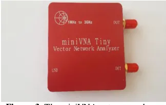
for lower costs; some VNAs are now available as compact units suitable for field use. Developments have progressed in recent years semiconductor devices for low cost signal analysis. This was then refined to the existing miniVNA1 are shown in Figure 3. The miniVNA Tiny is a low cost VNA solution less than €300 covering frequencies from 1MHz to 3GHz. These frequencies are good for most of IoT need: LPWAN around 868MHz and Bluetooth at 2.4GHz. The steps are 10Hz for a large precision. With two ports you can measure S11-powe r transmitted and received over the same port-and S21-power transmitted from port 1 and received over port 2. The miniVNA Tiny is an usb solution working with a computer connected to and a software running on the computer. The software is based on Java and may support different operating systems . The specifications of the miniVNA Tiny are given in Table 1.
Figure 2. Various uwb microstrip antennas
Figure 3. The miniVNA antenna analyzer
TABLE 1. The specifications of the miniVNA Tiny
Parameters Value s
Frequency range 1 MHz to 3 GHz
Ports 2 ports
Output power -6 dBm at 500 MHz
Dynamic range Up to 70 dB at 500 MHz
Connectors 2 x SMA
Power consumption 370 mA at 5 V (USB)
Weight 70 g
Size 66x66x28 mm
Software vna/J for Windows, Linux and MacOS
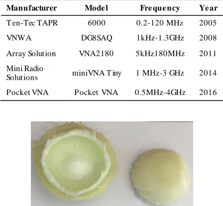
Besides, there are many economical portable PC-based VNAs which are much cheaper in the market . Their properties are given in Table 2. As a result; this device has the potential to be used in biomedica l applications, such as breast microwave imaging [14], and body bio-impedance measurement [15].
Furthermore, we created a breast phantom sample with dilelectric properties that mimic those of actual breast tissue as a preliminary study. As shown in Figures 4 and 5; this breast phantom consists of nested layers: skin, fat and glands, respectively. A trial measurement was performed in Figure 6 and a successful result was obtained. In the future work, several different phantoms will be created and different measurement scenarios will be made for further improve microwave breast cancer imaging technologies.
3. RESULTS
We analyzed the performance of antennas in this paper using references since there are various applications of
TABLE 2. The properties of various PC-based VNAs
Manufacturer Mode l Fre que ncy Ye ar
T en-Tec TAPR 6000 0.2-120 MHz 2005
VNWA DG8SAQ 1kHz-1.3GHz 2008
Array Solution VNA2180 5kHz180MHz 2011
Mini Radio
Solutions miniVNA T iny 1 MHz-3 GHz 2014
Pocket VNA Pocket VNA 0.5MHz-4GHz 2016
Figure 4. Photography of the breast phantom parts including
skin, fat and glands
Figure 5. Photography of the complete breast phantom
Figure 6. The measurement setup
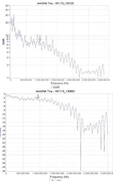
antennas in ultra wideband systems . To evaluate standing wave ratio (swr) and return loss of the antennas are performed. The results are illustrated in Figures 7, 8 and 9. To determine the exact amount of distortion, time domain received signals are calculated as well. The antenna satisfactorily meets the requirements and has an UWB attitude. The results of experiment led to a reflection coefficient of -10dB from 2.52 GHz to 2.76 GHz, from 1.49 GHz to 2.76 GHZ, from 1.96 to 2.76, respectively. Data showing sufficiently high gain over the required ultra-wide band which provides a good performance for the spectrum allocated to the UWB microwave medical applications by the FCC commission.
Figure 7. Results of swr, and return loss of (a) uwb
Figure 8. Results of swr, and return loss of (b) uwb microstrip antenna
Figure 9. Results of swr, and return loss of (c) uwb
microstrip antenna
4. CONCLUSION
This study was conducted in order to introduce the use of low-cost VNAs that can be easily set up in the laboratory, which may offer satisfactory performance compared to commercial, expensive VNAs. Measurements of antennas were performed and evaluated by using miniVNA Tiny which operates by radiating an electromagnetic wave through an antenna and measuring standing wave ratio (swr), return loss, and the magnitude of the complex impedance. The reasonable results indicate the good performance for UWB systems, especially biomedical applications. However, this device has the potential to be used in biomedical applications, such as breast microwave imaging, and body bio -impedance measurement. In future works, measurements will be carried out using miniVNA and these antennas on breast phantoms with tumor which will be produced using chemical materials further improve microwav e breast cancer imaging technologies .
5. ACKNOWLEDGEMENTS
This research was partially supported by Adana Science and Technology University Scientific Research Commission. Project Number: 18119003.
6. REFERENCES
1. Deschamps, G.A., "Microstrip microwave antennas", in Proceedings of the Third Symposium on the USAF Antenna Research and Development Program, Oct. (1953), 18 -22. 2. Gutton, H. and Baissinot, G., "Flat aerial for ultra high
frequencies", French Patent, Vol. 703113, (1955). 3. Munson, R., "Conformal microstrip antennas and microstrip
phased arrays", IEEE Transactions on Antennas and Propagation, Vol. 22, No. 1, (1974), 74-78.
4. Howell, J., "Microstrip antennas", IEEE Transactions on Antennas and Propagation, Vol. 23, No. 1, (1975), 90-93. 5. Garg, R., Bhartia, P., Bahl, I.J. and Ittipiboon, A., "Microstrip
antenna design handbook, Artech house, (2001).
6. James, J.R., Hall, P.S. and Wood, C., "Microstrip antenna: Theory and design, Iet, (1986).
7. Carver, K. and Mink, J., "Microstrip antenna technology", IEEE Transactions on Antennas and Propagation, Vol. 29, No. 1, (1981), 2-24.
8. James, J.R., "Handbook of microstrip antennas, IET, Vol. 1, (1989).
9. T abatabaeian, Z.S. and Neshati, M.H., "Sensitivity analysis of a wideband backward-wave directional coupler using neural network and monte carlo method", International Journal of Engineering Transactions B: Applications, Vol. 31, No. 5, (2018), 729-733.
11. Dashti, H. and Neshati, M.H., "Design investigation of microstrip patch and half-mode substrate integrated waveguide cavity hybrid antenna arrays", International Journal of Engineering-Transactions B: Applications, Vol. 28, No. 5, (2015), 686-692. 12. Dashti, H. and Neshati, M.H., "Comparative investigation of half-mode siw cavity and microstrip hybrid antenna using different patch shapes", International Journal of Engineering Transactions A: Basics, Vol. 27, No. 10, (2014), 1573-1580.
13. Balanis, C.A., "Antenna theory: Analysis and design, John wiley & sons, (2016).
14. Byrne, D., Sarafianou, M. and Craddock, I.J., "Compound radar approach for breast imaging", IEEE Transactions on Biomedical Engineering, Vol. 64, No. 1, (2017), 40-51.
15. Patil, A.S. and Ghongade, R., "Design of bioimpedance spectrometer", in 2016 International Conference on Advances in Computing, Communications and Informatics (ICACCI), IEEE. (2016), 2724-2728.
Low-cost Vector Network Analyzer for Biomedical Applications
TECHNICAL NOTEE. Avşar Aydin
Adana Alparslan Türkeş Science and Technology University, Department of Aerospace Engineering, Sarıçam, Adana, Turkey
P A P E R I N F O
Paper history:
Received 15 January 2019
Received in revised form 01 February 2019 Accepted 07 March 2019
Keywords:
Reflection Coefficient Standing Wave Ratio Low-Cost Vector Network Microstrip Antenns Ultra Wideband
هدیکچ
ی ( لمح لباق و تمیق نازرا هکبش رگلیلحت ک
VNA
سناکرف هک ) نآ
نیب 1 ات زترهاگم
3 GHz
یارب ،دهد یم ششوپ ار
( هداتسیا جوم تبسن و رگباتزاب بیرض
swr
یریگ هزادنا هلاقم نیا رد .دوش یم هدافتسا فلتخم تیرتساورکیم یاه نتنآ زا )
( دناب یانهپ هداعلا قوف تیرتساورکیم یاه نتنآ فلتخم یاه
UWB
ماجنا یکشزپ تسیز هنیمز رد یاهدربراک یارب ) یم
کی نتنآ باختنا .دوش شقن
مهم ی یکیژولویب یاه لانگیس رد فلتخم یاه تیعقوم صیخشت یارب د
ا در ریگ هزادنا . اهنتنآ ی
زا هدافتسا اب
miniVNA Tiny
جوم تبسن یریگ هزادنا و نتنآ قیرط زا یسیطانغمورتکلا جوم کی راشتنا اب هک دش ماجنا
( هداتسیا
SWR
اب .دنک یم لمع هدزاب تفا و ) ،لاح نیا
miniVNA Tiny
دیلوت یارب ناسآ یاه نتنآ و هنیزه مک یازجا
یاه متسیس یارب بوخ درکلمع دهد یم ناشن جیاتن .تسا
UWB
یکشزپ یرادربریوصت یدربراک یاه همانرب صوصخ هب ،
فیط رد هدافتسا یارب هنیزه مک سناکرف متسیس کی یارب تسا نکمم هاگتسد نیا ،لاح نیا اب .ویوورکیام نس
،تفاب یج
هنیس روموت صیخشت رد هوقلاب روط هب و هنیمز رب تراظن وش هتفرگ راکب
.د
doi: 10.5829/ije.2019.32.03c.07