AUTOMATIC VERTICAL STORING DEVICE FOR
DOMESTIC AND INDUSTRIAL USAGE
*M.Sejzu, **R.Govindaraj
*Department of Mechanical Engineering, SNS College of Engineering, Coimbatore, India
**Department of Mechanical Engineering, SNS College of Engineering, Coimbatore, India
ABSTRACT
In this emerging world, many organizations have been developed according to the needs of the people. In all the organizations and industries, many important things will be there which should be stored securely. There are various kinds of storing methods like storing in cupboards etc., which is not highly secured. Some materials can be stored very high, so that it will be difficult for the people to take and place it. So we initiated in doing a project on Automatic Vertical Storing Machine, which is highly secured and enables easy placement and replacement with the help of simple micro controller and proximity sensors. This device would save time and reduce manual efforts .This paper explains how the prototype works which is made for storing class room keys in the colleges as well as cell phones can also be stored in this device. By altering the designs it can be used in industrial storages for storing materials in the inventory.
Keywords: synchronous motor, micro controller, proximity sensor
INTRODUCTION
When we were studying about the conveyors and came to know that these conveyors are used for material transporting (i.e.) moving the material from one place to another for different purposes like assembling and packing etc. Then we came out with an idea that why can’t we use these conveyors as a storing device. In the vertical conveyors, initially the materials will be moved horizontally and then using the materials will move up vertically and then again at the top, the material is delivered out, so that the materials will be moved horizontally again. So racks can be fitted to the conveyor and some materials can be placed in the racks. These racks will not tilt when the vertical conveyor operates. Thus the materials which are placed in the racks can be stored and secured. The automation of rotational moment is achieved by the synchronous motor which works based on programmed instructions in microcontroller .The inputs will be obtained from proximity sensor placed in the arrangements.
DESCRIPTION OF PARTS
183
found in the bicycle, in which the pedal shaft carries a large sprocket-wheel, which drives a chain, which, in turn, drives a small sprocket on the axle of the rear wheel. Early automobiles were also largely driven by sprocket and chain mechanism, a practice largely copied from bicycles. Sprockets are of various designs, a maximum of efficiency being claimed for each by its originator. Sprockets typically do not have a flange. Some sprockets used with timing belts have flanges to keep the timing belt centered. Sprockets and chains are also used for power transmission from one shaft to another where slippage is not admissible, sprocket chains being used instead of belts or ropes and sprocket-wheels instead of pulleys. They can be run at high speed and some forms of chain are so constructed as to be noiseless even at high speed. Chainhave a surprising number of parts. The roller turns freely on the bushing, which is attached on each end to the inner plate. A pin passes through the bushing, and is attached at each end to the outer plate. Bicycle chains omit the bushing, instead using the circular ridge formed around the pin hole of the inner plate. Nylon gear is a device used to transmit the power from one source to another. In this project, we used nylon gear to transmit power from synchronous motor to the conveyor. Nylon gear is fitted to the shaft which is connected to the driving sprocket. Thus it makes the driving shaft to rotate. And with the help of driving shaft, the driven shaft also rotates Shaft A drive shaft, driveshaft, driving shaft, propeller shaft (prop shaft), or Cardan shaft is a mechanical component for transmitting torque and rotation, usually used to connect other components of a drive train that cannot be connected directly because of distance or the need to allow for relative movement between them. As torque carriers, drive shafts are subject to torsion and shear stress, equivalent to the difference between the input torque and the load. They must therefore be strong enough to bear the stress, whilst avoiding too much additional weight as that would in turn increase their inertia. To allow for variations in the alignment and distance between the driving and driven components, drive shafts frequently incorporate one or more universal joints, jaw couplings, or rag joints, and sometimes a splined joint or prismatic joint. Synchronous Motor As the name suggests Synchronous motors are capable of running at constant speed irrespective of the load acting on them. Unlike induction motors where speed of the motor depends upon the torque acting on them, synchronous motors have got constant speed-torque characteristics. Synchronous motors have got higher efficiency (electrical to mechanical power conversion ratio) than its counterparts. Its efficiency ranges from 90 – 92%.Micro Controller
A microcontroller is a small and low-cost computer built for the purpose of dealing with specific tasks, such as displaying information in a microwave LED or receiving information from a television’s remote control. Microcontrollers are mainly used in products that require a degree of control to be exerted by the user. Microcontroller has an input device in order to get the input and an output device (such as LED or LCD Display) to exhibit the final process. Let us look into the illustration of how a microcontroller works in a Television. The Television has a remote control as an Input device and the TV screen as the output device. The signal sent from the remote control is captured by the microcontroller. The microcontroller controls the channel selection, the amplifier system and picture tube adjustments such as hue, brightness, contrast etc.
The most commonly used proximity sensors are the inductive type which generate an electromagnetic field to sense metal objects passing close to the face. This is usually the easiest sensing technology to apply in applications where the metal target is within an inch or two from the sensor face. A proximity sensor can detect metal targets approaching the sensor, without physical contact with the target. Proximity sensors are roughly classified into the following three types according to the operating principle: the high-frequency oscillation type using electromagnetic induction, the magnetic type using a magnet, and the capacitance type using the change of capacitance
DESIGN OF PROCEDURE
Fabrication procedure
Turning A single-point turning tool moves axially, along the side of the work piece, removing material to form different features, including steps, tapers, chamfers, and contours. These features are typically machined at a small radial depth of cut and multiple passes are made until the end diameter is reached. Facing It is the process of machining the end of the work material which leads to material removal. During this process, the length of the work piece will be reduced. DrillingA drill enters the work piece axially through the end and cuts a hole with a diameter equal to that of the tool. Weldingis a metal joining process. Oxyacetylene gas welding is commonly used to permanently join mild steel. A mixture of oxygen and acetylene, burns as an intense / focused flame, at approximately 3,500 degrees centigrade. When the flame comes in contact with steel, it melts the surface forming a molten pool, allowing welding to take place
3d model of prototype Working model prototype
Design calculations for this prototype Calculation of length of chain in pitches
L = + A + + Y
Where, 3d model of prototype
185
n, N = tooth numbers of smaller and larger sprockets respectively. A =
C = center distance (mm) P = chain pitch (mm) X = Service Factor
Y = Number of pitches to be added to obtain an even number of pitches
Frame Calculation:
Base - 35*35 cm (L*B) Column - 55*10 cm (L*B)
Center distance of sprocket - 32 cm
For Chain:
C = 0.32m P = 0.01588m X= 1.03
Chain Length L = 1.3m Number of Link (n, N) = 82 No. of teeth in sprocket: Drive = 40
Driven = 40
WORKING PROCEDURE
works based on programmed instructions in microcontroller .The inputs will be obtained from proximity sensor placed in the arrangements.
Source code #define _XTAL_FREQ 4000000//crystallfreqr #include<pic.h> __CONFIG(0x20A4); __CONFIG(0X3FFF); #define RLY RC3 #define SW4 RD0 #define SW3 RD1 #define SW2 RC4 #define SW1 RD2 #define LED RE1 unsignedintmsec=0; unsigned char sec=0,min=0,hr=0; unsignedint count=0,key=0; #include "DELAY.h" #include "LCD8B16x2.h" #include "ADC_887.h" void main()
{ ANSELH=0x00; ANSEL=0x00; PORTA=0x00; PORTB=0x00; PORTC=0x00; PORTD=0x00; PORTE=0x00; TRISA=0x1F;//0b000 11111; TRISB=0x00; TRISC=0x91; TRISD=0x0F;// TRISE=0x00; T0IF = 0; //RESETTING STATES
TMR2IF = 0; TMR0=255;
OPTION_REG=0XE8; //1110 1000 //E8 T2CON = 0x1C; PR2 = 249; GIE=PEIE=1;
T0IE =1;
TMR2IE =1; __delay_ms(80); LCD_INIT(); LCD_STRING(0x80,TITLE) ; __delay_ms(300); if(EEPROM_READ(0xFF)= =255) { __delay_ms(1300); EEPROM_WRITE(0x00,cou nt); EEPROM_WRITE(0xFF,1); __delay_ms(300); key=1; } else key=count; __delay_ms(300); count=EEPROM_READ(0x0 0); LCD_INTEGER(0xC0,count ,3); LCD_INTEGER(0xC6,key,2 ); while(1)
{ if(SW1 && !RLY) { __delay_ms(300); while(SW1) { LED=1; key=1; LCD_INTEGER(0xC6,key,2 ); } LED=0; if(key!=count) RLY=1; }
if(SW2 && !RLY) {
187 key=2; LCD_INTEGER(0xC6,key,2 ); } LED=0; if(key!=count) RLY=1; }
if(SW3 && !RLY) { __delay_ms(300); while(SW3) { LED=1; key=3; LCD_INTEGER(0xC6,key,2 ); } LED=0; if(key!=count) RLY=1; }
if(SW4 && !RLY) { __delay_ms(300); while(SW4) { LED=1; key=4; LCD_INTEGER(0xC6,key,2 ); } LED=0; if(key!=count) RLY=1; } } }
void interrupt isr()
//Interrupt functions {
if(TMR2IF) {
TMR2IF=0;
CONCLUSION AND SCOPE FOR FUTURE WORK
Conclusion
Thus through this project, the materials can be stored properly without any damage and as this project is an enclosed setup, the materials in it is highly secured. Since the microcontroller and proximity sensors are used, this project is highly automated with a simple cost. The required rack will be delivered automatically with the use of proximity sensor. In the industrial point of view this prototype can be modified with hydraulic system and it can be used for industrial storing purposes.
Scope for future work
In future, the number of racks will be increased, so that the storage capacity will be increased. The system could be replaced with the rotating disc which holds the materials and vertical traversing arms which will pick and place the objects from the disc to delivery point as shown in the following figure and for improving the automation, barcode, thumb impression methods will be implemented at user accessing zone for increasing the security
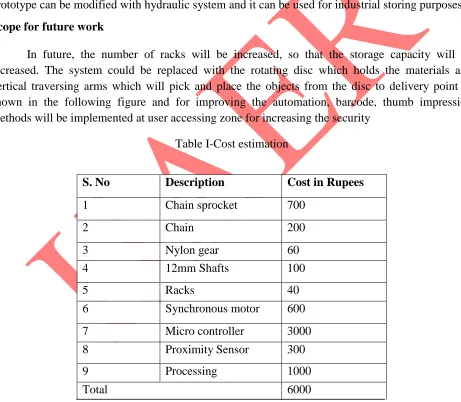
Table I-Cost estimation
S. No Description Cost in Rupees
1 Chain sprocket 700 2 Chain 200 3 Nylon gear 60 4 12mm Shafts 100 5 Racks 40 6 Synchronous motor 600 7 Micro controller 3000 8 Proximity Sensor 300 9 Processing 1000
189
Future design model
REFERENCES
[1]Microcontrollers - Ajay V Deshmukh ,Microcomputer Systems Architecture, Programming and Design - Yu – Cheng Liu, Glenn A. Gibson
[2] Augarten, Stan (1983). The Most Widely Used Computer on a Chip: The TMS 1000. State of the Art: A Photographic History of the Integrated Circuit (New Haven and New York: Ticknor & Fields). ISBN 0-89919-195-9. Retrieved 2009-12-23.
[3] http://www.sensors-transducers.machinedesign.com/guiEdits/Content/bdeee4/bdeee4_7.aspx [4] Digiscend (October 2014). "Conveyor Belt System Services". Digiscend.com.