MODELLING AND CHATTER CONTROL IN MILLING
Ashwini Shanthi.A, P. Chaitanya Krishna Chowdary, A.Neeraja , N.Nagabhushana Ramesh
Dept. of Mech. Engg Anurag Group of Institutions (Formerly C V S R College of Engineering)
Hyderabad, Telangana
ABSTRACT
Milling machines are used to machine flat surfaces but produce irregular surfaces. This is due to the presence of vibrations of milling tool and chatter on surface. The chatter, which accompanies the cutting process, is undesirable phenomenon. Vibration control in the milling process is the most important problem of the engineering industry. A review of research work performed in real time active vibration control and chatter suppression for milling process, as well as research work done on dynamic modeling of milling tool is presented.
Keywords— Milling, chatter, FRF, Fuzzy logic, Anti resonance, Absorber, Magnetic damper, Stability.
INTRODUCTION
Milling is widely used process for manufacturing various Mechanical components. If the material removal rate is more then the milling process is more efficient. For machine tool – work piece combination, the factors that influence the material removal rate are feed rate, depth of cut and spindle speed. Depth of cut may be both axial and radial depth of cut that influences more in material removal rate. The material removal rate is also limited by following factors:
1) Torque or power limitations of the drive motors on the machine.
2) Tool failure due to excessive wear or breakage
3) Chatter vibration
Milling is regarded as slow process and costly process. The main limitation of milling is caused by vibration of the machine tool and work piece. As the speed and the power of milling are increased, controlling the vibration of tool is most important. Cutting operation in milling is affected by two different kinds of vibration.
1) Self excited vibration at high spindle speed
2) Vibration at critical nature frequency.
Machine Tool Chatter or Chatter Vibrations.
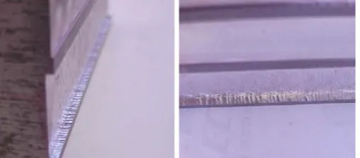
The chatter on the surface of work material in milling process is shown in Fig 1.
Fig 1. Chatter On The Surface In Milling Process
MODELLING
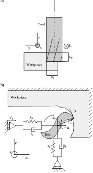
In the milling process, material is removed from the work piece by a rotating cutting tool. While the tool rotates, it translates in the feed direction at a certain speed. The block diagram of the milling process [4] is shown in Fig 2.
Chatter is mainly caused by the dynamic interaction of the cutting process and the machine tool structure. In cutting process, a force is generated between the work piece and the tool, which acts at an angle to the surface. This cutting force strains the structure elastically and causes relative displacement of the tool and work piece, which changes the
Fig 2. Block Diagram Of Milling Process
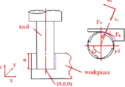
Fig 3. Representation Of Milling Process
tool work engagement. Due to this, there is a possibility of initial vibration to the self sustaining and build up, with the machine oscillating in one of its natural modes of vibration.
Poor machining results are the major problem of chatter vibrations in milling, with cutting tool damage and poor work piece quality. Several studies are performed about chatter and its suppression. Attention is concentrated on both machine tool and work material to suppress chatter.
Discussed a certain displacement of the cutter, related to the feed and rotation angle, is dictated to the spindle. Static chip thickness hstat is resulted to this displacement. To produce this
displacement, the cutter encounters a resistance force F due to the machine tool work material interaction, if the cutter is actually in cut. This resistance force results in the cutter displacement, u, which causes a difference between the prescribed displacement and actual displacement of the cutter. This produces tool vibrations, which causes wavy surface on the work piece. The next tooth in the cut continues in producing wavy surface resulting in chatter on the surface.
Fig 4. Dynamic Model Of Milling
Tangential and radial cutting forces on jth tooth are given as
Ft (j) = Kt a .h ( фj )
Fr (j) = Kr Kt .h (фj)
Where
A = axial depth of cut
Kt, Kr = Cutting constant coefficients
determined by experiment
h ( фj ) = Chip thickness
= [V Sin фj + Rjo (фj) - Rj (фj) ] g(фj)
v = feed per tooth
Rjo, Rj= Radial displacement of the cutter at the Previous and present cuts at the position (фj)
g(фj) = unit step function which determines whether jth tooth is in or out of the cut.
Where
x ( t) = Displacement of spindle in x direction
y (t) = Displacement of spindle in y direction
Nt = Tooth number of cutter
= Directional dynamic milling Coefficient
The time varying dynamic cutting forces are approximated by average component of the Fourier series expansion, α (t) can be expressed as:
Hence the cutting force reduces to :
Dynamic model for end milling cutter is given as :
forces
e-τD= Time delay operator
Assuming ωc as chatter Frequency, the system characteristic equation is obtained as:
PROGRESS IN THE DETERMINATION OF CHATTER IN MILLING
PROCESS
Chatter is undesirable phenomenon in the milling process. To reduce the chatter on tool and work material, several efforts are made during the last five decades. Early Research efforts from Arnold [1946], Tobias [1965], Tobias and Fishwick [1958], Tlusty and Polocek [1963], Koenisberger and Tlusty [1967] and Merit [1965] led to mathematical process models and the development of graphical charts, known as stability lobe diagrams. The stability lobe diagrams help in predicting stable cutting regions in high speed milling operations. The stability lobe diagrams (SLD) represent stability information as a function of control parameters, chip width and spindle speed.
Further studies on SLD formed the basis for regeneration of waviness or the over cutting of machined surface by a vibrating cutter. Methods are developed to reduce chatter by altering spindle speed, feed, both axial and radial depth of cut. Tool vibrations are minimized by proportionate variation in the above parameters. But considerable reduction in tool vibrations has not taken place by these efforts.
Proportional derivative fuzzy logic controller to suppress the chatter in milling process is designed [1]. The PD fuzzy logic controller by selecting combinations of the amplitude and frequency of spindle speed modulation on line keeps chatter indicator, R-value, close to a prescribed set point. The controller is successful in suppressing the chatter at only certain operating points. At some operating points the controller resulted in an oscillatory behavior of the process and the R – Value fluctuated significantly. Stability lobes are used to explain the suppression of chatter.
proved that this indicator works good in the relative cutting condition. Higher vibration suppression with increased values of speed modulation is observed for steel work material with the use of this indicator.
Applied fuzzy logic control to vary spindle speed modulation parameters for chatter suppression [3]. Proportional and proportional – integral fuzzy control algorithms are developed. Based on experimental observations and measurement of machined surfaces, set point in these controllers is established. Both controllers are able to regulate the chatter or vibration in milling process, with PI controller delivering more performance characteristics.
Kosuke Nagaya etal [5] presented a method of micro vibration control of milling machine heads by using a vibration absorber. An auto tuning vibration absorber is created. The anti resonance produced by auto tuning vibration absorber is not sufficient to suppress higher mode vibration. Therefore auto tuning magnetic damper is employed for suppressing higher mode vibrations.
A method for predicting chatter stability for milling system is further developed by Tony. L. Schmitz etal [4]. The temporal finite element analysis (TFEA) method development by Bayly et al computes an analytic solution for the cutter displacement when it is not in contact with the work piece. When in contact, the time in the cut is broken up into multiple elements and the vector displacement during a single element is approximated as a linear combination of polynomial trial functions. The Tluusty and Altintas and budak methods analytically transform the time dependent dynamic milling equations into a time invariant, but radial immersion- dependent system.
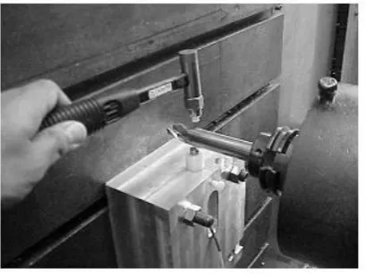
Tony L. Schmitz etal [6] constructed stability lobe diagrams using rotating tool FRF measurement setup shown in Fig.5.
Fig 5. Rotating Tool Frf Measurement Set Up
Tool : High speed steel cutting tool
Diameter : 19.05 mm
Overhang : 102 mm
Tool Frequency response functions (FRF) are measured at various speeds by this set up. FRF comparisons for 0 rpm, 11000 rpm, 23000 rpm is shown in Fig 6.
Fig 6. Frf Comparison For 0 Rpm,11000 Rp,23000 Rpm.
A comparison of non-rotating and rotating FRF stability lobe diagrams is shown in Fig.7.
Fig 7. Comparison Of Rotating And Non-Rotating Frf Stability Lobe Diagrams
Fig 8. Machining Test Set Up With Microphone
CONCLUSION
Milling is widely used in industry. The dynamic analysis and active vibration control of the milling machinery are important engineering problems for both academicia and industry. In this paper, a review of the modeling of machine tool and chatter control of milling process was conducted.
The major problem faced by the chatter of tool and surface of work material is reduction in quality of the component produced. Tool wear and economics of the process are additional problems .The research work in the area of chatter reduction is presented in this paper so that more active attention is concentrated in this area. The stability lobe diagrams, FRF measurements, usage of auto tuning magnetic damper reduce the chatter considerably in the milling process. Further there is scope for further reduction of chatter by deep investigation in the design of milling tools.
REFERENCES
[1] E.soliman, F.Ismail: “chatter suppression by adaptive speed modulation”, International Journal
of Machine Tools & Manufacture, 37 (3) (1997) 355-369
[2] E.G.kubica, F.Ismail: “Active suppression of chatter in peripheral milling Part 1.A statistical
indicator to evaluate the spindle speed modulation method”, International Journal of Advanced manufacturing technology (1995) 10:299-310
[3] E.G.kubica, F.Ismail: “Active suppression of chatter in peripheral milling Part 1.A statistical
indicator to evaluate the spindle speed modulation method”, International Journal of Advanced manufacturing technology 12(4)(1996) 236-245
[4] R.P.h.Faassen, N.van de Wouw, J.A.J.Oosterling, H.Nijmeijer: “Prediction of regenerative