Available Online at www.ijpret.com 31
INTERNATIONAL JOURNAL OF PURE AND
APPLIED RESEARCH IN ENGINEERING AND
TECHNOLOGY
A PATH FOR HORIZING YOUR INNOVATIVE WORKSTRUCTURAL BEHAVIOUR ANALYSIS OF INTEGRAL TYPE BRIDGE WITH
INFLUENCE OF MODULUS OF SUBGRADE REACTION OF SOIL
SHREERAM P. PRAJAPATI1, NOOPUR A. SHAH2, JIGAR ZALA3
1. Post Graduate Student, Department of Civil Engineering, SAL Institute of Technology and Engineering Research, Ahmedabad, Gujarat India 2. Asst. Professor, Department of Civil Engineering, SAL Institute of Technology and Engineering Research, Ahmedabad, Gujarat India-380060 3. Asst. Professor, Department of Civil Engineering , SAL Institute of Technology and Engineering Research, Ahmedabad, Gujarat India-380060
Accepted Date: 22/05/2018; Published Date: 01/06/2018
\
Abstract: - Integral Abutment Bridges (IABs) are joint less and bearing less bridges whereby the deck is continuous and monolithic cast with abutment walls. The behaviour of Integral abutment bridge is interdependent between its structural components and soil medium, because complex behaviour of soil. IABs are complex structures due to the nonlinearity and uncertainties in bridge materials and soil boundaries. Modulus of subgrade reaction (Ks) of soil is the bearing capacity per unit settlement. The present work includes the modelling of Integral abutment bridges with simple soil springs stiffness based on earth pressure theory for the analysis. Three models of bridge length 50m, 100m and 150m consists of two lanes and two to four spans respectively analyze as per IRC guidelines. Temperatures change daily and seasonally the lengths of integral bridges increase and decrease, pushing the abutment against the approach fill and pulling it away. As a result, the bridge super-structure, the abutment and foundation soil are all subjected to cyclic loading, and understanding their interactions is important for effective design and satisfactory performance of integral bridges. Applying the earth pressure loads is to assign appropriate spring stiffness to the abutment to represent the soil properties. The earth pressure on the abutments can be considered using Winkler soil constitutive model along with appropriate pressure coefficient Ks with different soil types.
The final aim of this study is to propose modelling of integral abutment bridge system with influence of modulus of subgrade reaction which can allow predictions of dynamic response based on the results of static relative displacement studies coupled with simple soil stiffness and study observed trends in bending moment, shear force, deflection in longitudinal girders, super-structure behaviour, abutment displacement subjected to the dynamic loading using standard software SAP2000 series Csi bridge. The conclusion shows that depending on Temperature variation, soil conditions, soil parameters and backfill stiffness the forces generated in the structure vary significantly.
Keywords: Integral abutment bridge, modulus of subgrade reaction, soil stiffness, Csi bridge, structural response
Corresponding Author: SUMIT H. PAREKH Access Online On:
www.ijpret.com
How to Cite This Article:
Shreeram P. Prajapati, IJPRET, 2018; Volume 6 (10): 31-46
Available Online at www.ijpret.com 32 INTRODUCTION
The bridge is a structure designed to carry the users from point A to point B crossing an obstacle, thus making it very important to know about the loads acting on the bridge as well as the structural response to those loads. There are many different types of bridges which fulfil different requirements, e.g. suspension bridges, cable stayed bridges and arch stayed bridges. These bridges are in general used for long spans and long distances. For shorter spans, frame bridges or beam bridges are usually used. These bridges can be made either with or without joints transferring movements and forces that act on the bridge structure. One major problem regarding bridges with joints are the fact that the joints must not be exposed to water or dirt in order to function sufficiently. This will give high maintenance costs, something that will be avoided using joint less bridge, where instead moments are introduced to the rigid connections.
To categories joint less bridges, the expressions integral bridges or integrated abutment bridges are often used. Some examples of integrated bridges are slab bridges, frame bridges, beam bridges or semi-integrated bridges. In the integral bridges, the abutments are used to lead both horizontal and vertical forces into the ground. A foundation of either spread foundations or piles are then used.
Bridges are generally designed as structures with bearings and roller connections at their supports. This is for several reasons, such as severity of the weather (temperature), movements of the earth, traffic loading condition, and the material which is used in construction, any of which could cause expansion and contraction to the bridge superstructure. For conventional bridges, expansion and contraction stresses are relieved by adding expansion joints in the structure. However, bearings and expansion joints are recognized as a reason for the high maintenance cost of bridges. The weak points in the bridges are also considered to occur at these bearings and joint connections, especially because they are vulnerable to environmental problems such as corrosion from humidity or ice and snow.
An alternative bridge construction is the integral bridge, which does not have expansion joints or bearings. Instead, integral bridges have a rigid structure and all of the loads, including stresses induced by expansion and contraction, are transferred directly to the abutments and sub-structures.
A. Concept of integral bridge
Available Online at www.ijpret.com 33
bridge. IABs have a lower construction cost and much lower life cycle costs because of minimal maintenance. Retrofitting traditional bridges with IAB features has also shown to be cost effective.
1. Structural arrangement
Integral bridges are specific when compared with traditional girder bridges, because they do not contain expansion joints and bearings. The elimination of these structural elements separating the superstructure from the substructure leads to many differences between integral bridges and traditional girder bridges.
Figure: 1 Structural arrangement of integral bridge and conventional bridge
2. Statical action
Differences in structural arrangements of integral bridges and traditional girder bridges lead to differences of their statical action. The most important differences are following:
1) Rigid frame joint between a super-structure and a sub-structure,
2) Interaction between the super-structure, the sub-structure and the surrounding soil,
3) Restraint of free expansion of the superstructure.
Available Online at www.ijpret.com 34
bearings. The super-structure of integral bridge is fixed to the sub-structure, all displacements and rotations of the Super-structure is transmitted to the sub-structure. During the thermal expansion, the abutments are pushed into the soil of backfill, which brings about passive earth pressures acting on the abutments. The movements of the superstructure are restrained by the stiffness of the abutments and by the earth pressure acting on the abutments. This causes an interaction of the super-structure, the sub-structure and the surrounding soil.
Figure: 2 Deformations of integral bridge
3. General loads on integral bridge
A. Temperature load
Temperature loads affect bridges due to stress changes, for example when the concrete is heated up, it expands, and when it cools down it contracts again. The movement mainly happens in the horizontal direction. Concrete is a material with a relatively low heat conduction capacity, meaning that the heat transfer inside the material is low, making it more sensitive for thermal variations because large differences in temperature will arise within the structure.
B. Earth pressure
Soil can be divided into two main groups, cohesion soil and friction soil sand. The friction soil is
characterized by the internal friction angle 𝜙 which describes the angle of the line for the shear
Available Online at www.ijpret.com 35
C. Lateral earth pressures
The vertical loads, both external loads and the weight of the soil, spreads down in the ground. The self-weight of the soil magnifies with increasing depth and the stresses are calculated by multiplying the weight of the soil with the depth. To transform the vertical loads into horizontal
components, the stress is multiplied with the earth pressure coefficient 𝐾. The coefficient 𝐾0
represent the earth pressure coefficient at rest, 𝐾𝑎 the earth pressure coefficient for active
earth pressure and 𝐾𝑝 is the coefficient for the passive earth pressure.
𝐾0 = 1−sin(𝜙′) …..(1)
𝐾𝑎= tan2 (45° − 𝜙’/ 2) …..(2)
𝐾𝑝 = tan2(45°+ 𝜙’/ 2) …..(3)
where:
𝜙’= internal friction angle
D. Traffic loads
The traffic load is defined as a variable load, and thus many different load models exist to compensate for the many different outcomes of traffic. The only traffic load contributing to the horizontal displacement of the back wall is the braking force.
E. Surcharge loads
If a vehicle is standing on the road, beside the bridge, the load is taken up by the soil. The horizontal component of this load, decided by the earth pressure coefficient, will induce an active earth pressure on the bridge back wall, which in turn will cause a passive pressure in the other side. This type of load is called surcharge load.
4. Soil constitutive model
A. Winkler Model approach for computing stiffness of soil
The Winkler model is easy to implement in a structural system. The stiffness of a discrete spring
ki can be estimated with different approaches but is always defined as a relation between the
settlement δi and reaction force Ri in a point. For one specific point the relation can be written
Available Online at www.ijpret.com 36
Ki=Ri/δi …. (4)
Where:
Ki=stiffness of discrete spring
Ri=reaction force at point
δi=settlement
In a simple model, the spring stiffness can be assumed to be uniformly distributed. A normal approximation for calculation of settlements is to assume a 2:1 stress distribution in the soil. The stiffness for discrete springs is calculated by dividing the vertical load affecting one spring q*s by the settlement δ, where s is the spacing between the springs. With uniform spring
stiffness, constant E Modulus Es through the depth in the soil and assuming 2:1 stress
distribution, the stiffness of discrete springs is determined with equation, where L is the length of the super-structure and H height of the subgrade.
Ki=qs/δi …. (5)
Winkler model is the simplest structural model. The primary deficiency of the model is that the shear capacity of the soil is neglected. As a result of omitting the shear stresses, displacement has no spread in transverse direction. Therefore, displacement discontinuity appears between loaded and unloaded surfaces.
Objectives
1. The primary aim of this research is to contribute to the knowledge on the performance of engineered backfill soil materials and structural response of integral bridges. This would support better informed decisions by engineers during design, construction and use.
2. A comprehensive literature review on integral bridges and integral bridge soil structure interaction problems as it relates to the backfill and foundation soil was undertaken to review the concept of the integral bridge.
Available Online at www.ijpret.com 37
MATERIALS AND METHODS
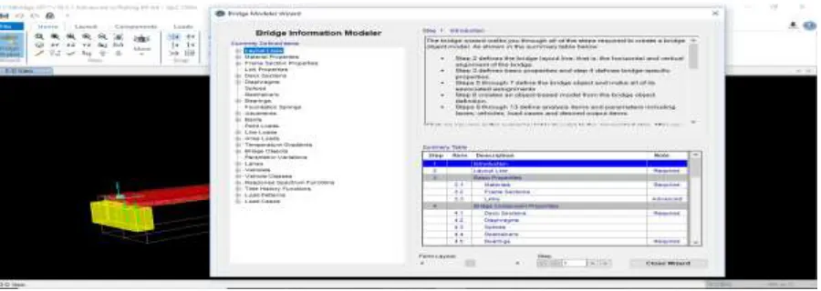
1. Bridge information modeller process
Figure 3: Bridge modeller process in Csi bridge
2. Documentation
Bridge information modeller defines all the steps by step definitions of modelling as shown in below figure.
Available Online at www.ijpret.com 38
3. DEFINITION OF MODEL
1. Model Data:
• Bridge layout line data
• Length of bridge=50 m, 100 m and 150 m
• Spans of bridge for 50 m bridge=Two equal span of 25 m
• For 100m bridge=Three equal spans
• For 150m bridge=Four equal spans
• Horizontal and vertical layout=straight
• Centerline offset=1.825 m
• Lane width=3.65 m
• Abutment: Depth=3 to 6 m
• Width=2.5 m
• Cap bent: Depth=2 to 3 m
• Width=1.6 m
• Pile: 1 to 1.5 m dia.
2. Material Properties
The material properties used in the models are as follows:
• Steel girders=Fe345
• Concrete section=M30
• Rebar materials=HYSD 415
• Poisson’s Ratio= 0.3
Available Online at www.ijpret.com 39
3. Loading Data
The loads which are considered for this analysis are Dead loads, Live loads.
1) Dead load
• Asphalt load: 2 kN/m
• Railing load: 1 kN/m
2) Live load (Moving loads)
• As per IRC design guidelines.
• Vehicle classes: IRC 70R
• IRC AA Tracked
• IRC AA Wheeled
• Load combination: (DL+LL)
• Load cases: Static linear and Moving live load
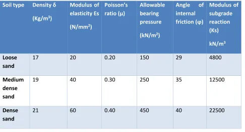
Table 1: Parameters for Modulus of subgrade reaction values
Soil type Density δ
(Kg/m3)
Modulus of elasticity Es
(N/mm2)
Poisson’s ratio (μ)
Allowable bearing pressure
(kN/m2)
Angle of internal friction (ϕ)
Modulus of subgrade reaction (Ks)
kN/m3
Loose sand
17 20 0.20 150 29 4800
Medium dense sand
19 40 0.30 250 35 12500
Dense sand
Available Online at www.ijpret.com 40 Clayey
med dense sand
16 8 0.25 180 30 9000
Silty medium dense sand
17 10 0.30 190 32 9500
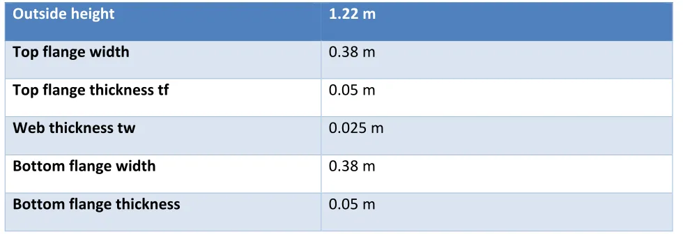
Table 2: Fe345 steel girder data
Outside height 1.22 m
Top flange width 0.38 m
Top flange thickness tf 0.05 m
Web thickness tw 0.025 m
Bottom flange width 0.38 m
Bottom flange thickness 0.05 m
Table 3: Analysis of model and outcome response
LOAD CASES BRIDGE RESPONSE OUTPUT DATA
Static linear Displacement
Available Online at www.ijpret.com 41
4. Bridge models
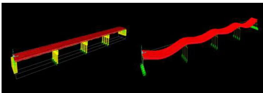
Figure 5: Model of 50m length bridge consists of two equal spans of 25m each and deformation shape (DL+LL) combination
Figure 6: Model of 100m length bridge consists of three equal spans and Deformed shape (DL+LL) combination
Available Online at www.ijpret.com 42
RESULT AND DISCUSSION
1. Results:
Table 4: Axial force (P max) kN entire bridge section
Length of bridge (m)
Loose sand 4800
kN/m2/m
Clayey medium dense sand 9000
kN/m2/m
Silt medium dense sand 9500
kN/m2/m
Medium dense sand 12500
kN/m2/m
Dense sand 22500
kN/m2/m
50 m 101 143.75 148.60 180.82 202.76
100 m 203.33 336.55 343.72 418.02 509.99
150 m 402.79 432.18 448.22 467.09 517.13
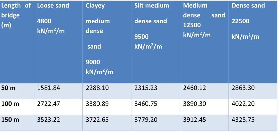
Table 5: Shear force (V max) kN Entire bridge section
Length of bridge (m)
Loose sand
4800 kN/m2/m
Clayey
medium dense
sand
9000 kN/m2/m
Silt medium
dense sand
9500 kN/m2/m
Medium dense sand 12500
kN/m2/m
Dense sand
22500
kN/m2/m
50 m 1581.84 2288.10 2315.23 2460.12 2863.30
100 m 2722.47 3380.89 3460.75 3890.30 4022.20
Available Online at www.ijpret.com 43 Table 6: Bending moment (M max) kN.m Entire bridge section
Length of bridge (m)
Loose sand
4800 kN/m2/m
Clayey
medium dense
sand
9000 kN/m2/m
Silt medium
dense sand
9500 kN/m2/m
Medium dense sand 12500
kN/m2/m
Dense sand
22500
kN/m2/m
50 m 7001.35 10595.0 10667.25 12232.75 14967.66
100 m 9325.62 12132.16 12320.75 13475.12 17419.40
150 m 18220.90 19002.14 19212.66 21975.40 22005.60
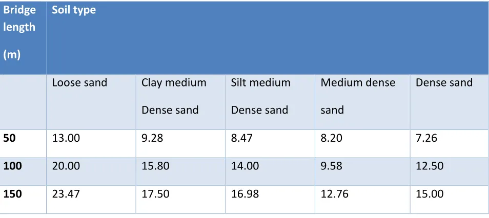
Table: 7 Abutment displacement (Top) in mm
Bridge length
(m)
Soil type
Loose sand Clay medium
Dense sand
Silt medium
Dense sand
Medium dense
sand
Dense sand
50 13.00 9.28 8.47 8.20 7.26
100 20.00 15.80 14.00 9.58 12.50
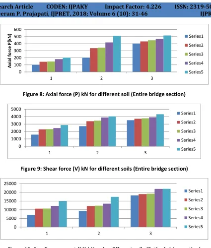
Available Online at www.ijpret.com 44 Figure 8: Axial force (P) kN for different soil (Entire bridge section)
Figure 9: Shear force (V) kN for different soils (Entire bridge section)
Figure 10: Bending moment (M) kN.m for different soils (Entire bridge section)
2. Conclusion
The conclusions achieved from present work are:
As the bridge length increases the axial force and girder bending moment increases. The
bridge length is also influence on the negative girder bending moment which is increase as bridge length increases.
0 100 200 300 400 500 600
1 2 3
A xi al for ce P(kN ) Series1 Series2 Series3 Series4 Series5 0 1000 2000 3000 4000 5000
1 2 3
Series1 Series2 Series3 Series4 Series5 0 5000 10000 15000 20000 25000
1 2 3
Series1
Series2
Series3
Series4
Available Online at www.ijpret.com 45
The additive axial force and bending moment (positive and negative) in integral bridge due
to thermal expansion of bridge deck become larger due to stiffness of backfill material.
The bending moment and displacement of the deck slab increase linearly with increase in
temperature.
The parametric study on abutment depth shows greater passive pressure and modulus of
subgrade reaction but reduction in displacement.
After study it was noted that behaviour of the super-structure of an integral bridge was
influenced by type of loading magnitude on super-structure and backfill soil stiffness.
ACKNOWLEDGMENT
I would like to extend my sincere thanks to Asst. Prof. Mrs. Noopur Shah and Jigar zala for his guidance and constant support in the project.
REFERENCES
Standard codes:
1. IS: 456-2000, Indian Standard Code of Practice for Plain and Reinforced Concrete
2. IRC: 78-2014, Standard Specifications and Code of Practice for Road Bridges- SECTION: VII. 3. IRC 6.2014, Standard specification and code of practice for Road and Bridges Section Load and stress
4. IRC 5.2015, Standard specification and code of practice for Road and Bridges section I Load and stress
5. Design of Bridge Structures by T.R. Jagadeesh and M.A. Jayaram
6. Scott A. Civjan, Emre Kalayci, Brooke H. Quinn, Sergio F. Bren, Chad A. Allen “Observed integral abutment bridge substructure response” ISSN: 0141-0296 Engineering structures. @2013 Elsevier Ltd. All rights reserved.
7. Aslam Amirahmada and A. Rahman Al-Sinaidia “Analysis of Integral Bridges by Finite Element Method” ISSN: 1877-7058 Procedia Engineering @ 2013 the Authors Published by Elsevier Ltd. 8. WooSeok Kima, Jeffrey A. Lamanb “Integral abutment bridge response under thermal loading” ISSN: 01410296 Engineering structures @2010 Elsevier Ltd. All rights reserved.
Available Online at www.ijpret.com 46
10. M. GadElRab Hussein, “Experimental Evaluation of the Subgrade Reaction and Soil Modulus
Profiles for Granular Backfills” Al-Azhar University, Nasr City, Cairo, Egypt Current Visiting Research at McGill University, Montreal, Quebec, Canada Conference paper 2009 GeoHalifax.
11. Emre Kalayci, Scott A. Civjan, Sergio F. Brena “Parametric study on the thermal response of
curved integral abutment bridges” ISSN: 0141-0296 Engineering Structures. 2012 Elsevier Ltd. All rights reserved.
12. Murat Dicleli, Suhail M. Albhaisi “Performance of abutment–backfill system under thermal
variations in integral bridges built on clay” ISSN: 0141-0296 Engineering Structures, 2004 Elsevier Ltd. All rights reserved.
13. Murat Dicleli, Semih Erhan “Effect of soil bridge interaction on the magnitude of internal
forces in integral abutment bridge components due to live load effects” ISSN: 0141-0296 Engineering structures.2009 Elsevier Ltd. All rights reserved.
14. R. Ziaie-moayed and M. janbaz “Effective parameters on Modulus of Subgrade Reaction in
clayey soils” ISSN: 1812-5654 Journal of applied science 9, 2009 Iran.
15. Constantine Spyrakosa, George Loannidis “Seismic behaviour of a post- tensioned integral