Available Online at www.ijpret.com 235
INTERNATIONAL JOURNAL OF PURE AND
APPLIED RESEARCH IN ENGINEERING AND
TECHNOLOGY
A PATH FOR HORIZING YOUR INNOVATIVE WORK
A NEW BIST ARCHITECTURE FOR TEST PER CLOCK AND TEST PER SCAN
SCHEMES
R SWATHI
Assistant Professor, Dept of ECE, Apollo Engineering College, Chennai, Tamilnadu, India.
Accepted Date: 22/11/2014; Published Date: 01/12/2014
\
Abstract: Test pattern generator (TPG) is used to generate test vectors .The test vectors are to be
applied to the circuit under test(CUT) which consumes more power and has high switching activity. TPG usually produces repeated test patterns and are not uniformly distributed .As they are not uniformly distributed their test length get increased. Repeated test pattern prolongs the test time and reduces the test efficiency. This project proposes a novel test pattern generator (TPG) for built-in self-test. Our method generates multiple single input change (MSIC) vectors in a pattern, i.e., each vector applied to a scan chain is an Single Input Change (SIC) vector. It does not contain any repeated test pattern. So the test time gets reduced and has high test efficiency. A reconfigurable Johnson counter is developed to generate a class of minimum transition sequences. The proposed TPG is Flexible to both the test-per-clock and the test-per-scan schemes. The minimum transition sequences are analyzed to extract a class of MSIC sequences. Analysis results shows that the produced MSIC sequences have the favorable features of uniform distribution and low switching activity.
Keywords: Built In Self Test, Multiple Input SignatureRegister Multiple Single Input Change Pseudo
Random Number Generator Test Pattern Generator
Corresponding Author: MS. R. SAWTHI
Access Online On:
www.ijpret.com
How to Cite This Article:
Available Online at www.ijpret.com 236 INTRODUCTION
A built-in self-test (BIST) or built-in test (BIT) is a mechanism that permits a machine to test itself. The BIST name and concept originated with the idea of including a pseudorandom number generator (PRNG) and cyclic redundancy check (CRC) on the integrated circuits(IC). If all the registers that hold state in an IC are on one or more internal scan chains, then the function of the registers and the combinational logic between them will generate a unique CRC signature over a large enough sample of random inputs. So all an IC need do is store the expected CRC signature and test for it after a large enough sample set from the PRNG. The CRC comparison with expected signature or the actual resultant CRC signature is typically accessed.
II. TESTING
Circuit manufacturers must thoroughly test their products before delivering them to customers. The causes of circuit failure can be divided into two main categories: design errors and manufacturing defects.
Design errors are caused by errors in the layout. If the errors can be eliminated by changing the layout, then it is considered a design error. To detect design error by simulating the circuit and testing the simulation. No simulation can perfectly predict a real circuit. For example, most simulation cannot predict any latch up problem. Manufacturing defects are caused by random variations in the manufacturing process can cause malfunctions in circuit components. These defects can occur even in circuits that have no design errors.
III.SINGLE INPUT CHANGE (SIC) VECTORS
Delay fault testing allows testing for delay faults. A delay fault occurs in a circuit when one or more paths in the circuit fail to propagate a signal within the time interval specified by the clock period. Detection of delay faults requires two-pattern tests. An initialization vector is applied and the circuit is allowed to stabilize. Then, the test vector is applied and the circuit outputs are sampled at clock speed. The response is then compared to that of the fault-free circuit to determine the presence or the absence of a delay fault. Hence, correct operation of a circuit at the intended speed can only be guaranteed if there is no delay fault in the circuit.
Available Online at www.ijpret.com 237 the means to test for delay faults. PDF’s are classified, according to their testability, as singly-testable (ST) or non-ST. An ST PDF affects the circuit speed, and has at least one test that is either robust or valid table non-robust or non-robust. Robust and valid table non-robust tests guarantee detection of the target fault in the presence of other PDFs. A non-robust test guarantees detection in the case of a single PDF, but may become invalid when there are multiple PDFs. A non-ST PDF has neither a robust nor a valid table non-robust nor a non-robust test. These PDF’s either do not affect the speed, or may affect it only if many non-ST PDF’s simultaneously exist. Therefore, delay tests with 100 % ST PDF coverage guarantee the speed of a circuit under a single PDF assumption.
A sixteen-valued algebra is used for both rising and falling PDF’s that are concurrently simulated. With this algebra, Boolean operations directly give the input-output relationships for gates. Using machine-word parallelism in all stages of computation, the circuit is simulated by assigning random values to its inputs. Transitions are then propagated from each input while all others remain steady. Finally, detected PDF’s are recorded. In one pass, both transitions are simulated from all inputs concurrently.
A sixteen-valued algebra is used for both rising and falling PDF’s that are concurrently simulated. With this algebra, Boolean operations directly give the input-output relationships for gates. Using machine-word parallelism in all stages of computation, the circuit is simulated by assigning random values to its inputs. Transitions are then propagated from each input while all others remain steady. Finally, detected PDF’s are recorded. In one pass, both transitions are simulated from all inputs concurrently.
Built-in self-test (BIST) schemes can be classified into (a) test-per-clock and (b) test-per-scan, according to the way in which test patterns are applied to the CUT. In test-per-clock BIST, the outputs of a test pattern generator are directly connected to the inputs of a circuit-under-test (CUT) and a new test pattern is applied to the inputs of the CUT at every clock. Also, the response to a test pattern applied to the CUT is loaded into a response analyzer at every test cycle.
Available Online at www.ijpret.com 238 during scan shifting. Hence, average heat dissipation can be reduced by reducing switching activity during scan operation.
A stuck-at fault is a particular fault model used by fault simulators and automatic test pattern generation (ATPG) tools to mimic a manufacturing defect within an integrated circuit. Individual signals and pins are assumed to be stuck at Logical '1', '0' and 'X'. For example, an output is tied to a logical 1 state during test generation to assure that a manufacturing defect with that type of behavior can be found with a specific test pattern. Likewise the output could be tied to a logical 0 to model the behavior of a defective circuit that cannot switch its output pin. Not all faults can be analyzed using the stuck-at fault model. Compensation for static hazards, namely branching signals, can render a circuit un testable using this model. Also, redundant circuits cannot be tested using this model, since by design there is no change in any output as a result of a single fault.
IV A.RECONFIGURABLE JOHNSON
COUNTER
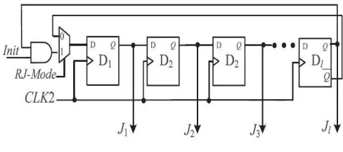
Designed for a short scan length, we develop a reconfigurable Johnson counter to generate an SIC sequence in time domain. As shown in Figure1, it can operate in three modes.
Fig 1 Reconfigurable Johnson Counter
B.MULTIPLE INPUT SIGNATURE
REGISTERS
Available Online at www.ijpret.com 239 The Design of MISR is shown in Bellow Diagram. For BIST of multiple output circuits, MISR are extensively utilized in practice due to their easy and low cost implementation and efficient fault coverage. MISR, in principle is not different from the single input signature analyzer, but instead of taking one serial input from the first flip-flop, every flip-flop in the MISR has one input coming from the primary outputs of the to be tested circuit as shown in figure 2 Multiple input signature register acts as test pattern generator. This additional function helps to reduce hardware overhead and testing time, when BIST (built-in self-test) structures are integrated on the chip, because the MISR can at the same time generate test patterns and collect test responses.
Fig 2 Multiple Input Signature Register
A formula is presented, which determines the number of clock cycles needed to generate a given number of random patterns. Finally we suggest a method for how the number of test patterns can be reduced when the MISR acts as test pattern generator and compressor in a feedback loop.
V.PROPOSED SYSTEM
A. MSIC-TPGs FOR TEST-PER-CLOCK
Available Online at www.ijpret.com 240 Fig Simulation of Test Per Clock (Johnson Based)
B. MSIC-TPGs FOR TEST PER SCAN SCHEMES
The MSIC-TPG for test-per-scan schemes is illustrated in below Figure 6.2. The stage of the SIC generator is the same as the maximum scan length, and the width of a seed generator is not smaller than the scan chain number. The inputs of the XOR gates come from the seed generator and the SIC counter, and their outputs are applied to M scan chains, respectively.
Fig 3 Test Per Clock
Available Online at www.ijpret.com 241 The control signals of the test per clock scheme are reset, clock, and initialisation. Depending upon these signals the outputs are generated in the johnson counter and the seed generator .the output from these are exored to get the test pattern. The test pattern thus generated are of single input change in which the time required to test the circuit is reduced and hence the switching activity get reduced.
Fig 4 Test Per Scan
The output of the test pattern generation of the combinational logic is tested and the resulting patterns are given to the misr and the output from the scan chains are also given to the misr. The resulting test patterns are single input change and are used to test both sequential and combinational circuits. The seed circuit will generate the seed which is used to test the circuit. There are certain rules in which the output of the seed generator is to be used. Thus the seed generator is used to derive the necessary test patterns are used to exor with the resulting circuit.
Available Online at www.ijpret.com 242 Johnson counter will act as a normal counter. In the test per scan the data will not be produced depending on the clock cycle. It will depend on the scan chain and the scan flips flops. The output from the scan chain and the scan flipflops are exored and it will be given to the MISR and the test patterns are generated. The generated test patterns are of a single input change as shown in the figure 8.4 and hence the switching activity gets reduced.
Fig 8.4 Simulation of Test Per Scan (Johnson Based)
Thus in the test per scan the combinational logic circuit is tested and the resulting test patterns are generated are given to the MISR. Thus the control signal of the test per scan is similar to that of test per clock schemes except the clock cycles. In the test per scan the test patterns that are generated are of single input change and there are no repeated test patterns. As there are no repeated test patterns the test efficiency is increased.
Test per scan is more efficient than the test per clock scheme as the test efficiency is higher when compared to the test per clock scheme.
VI.CONCLUSION:
Available Online at www.ijpret.com 243 REFERENCES:
1. Abu-Issa. A and Quigley. S, (2009),῾Bit-swapping LFSR and scan-chain ordering: A novel technique for peak- and average-power reduction in scan-based BIST᾽, IEEE Trans. Comput. Aided Design Integr. Circuits Syst., vol. 28, no. 5, pp. 755–759
2. Bonhomme. Y, Girard. P, Guiller. L, Landrault. C, and Pravossoudovitch. S, (2001),῾A gated clock scheme for low power scan testing of logic ICs or embedded cores᾽, in Proc. 10th Asian Test Symp., pp. 253–258.
3. Corno. F, Rebaudengo. M, Reorda. M, Squillero. S, and Violante. M (2000), ῾Low power BIST via non linear hybrid cellular automata᾽, in Proc. 18th IEEE VLSI Test Symp., pp. 29–34.
4. Girard P, Guiller. L, Landrault. C , Pravossoudo vitch S and Wunderlich H.J (2001) ῾A Modified Clock Scheme for a Low Power BIST Test Pattern Generator ᾽, IEEE VLSI., vol 45,no. 8,pp. 345-350.
5. Girard. P, Guiller. L, Landrault. C, Pravossoudovitch. S, Figueras. S, Manich. S, Teixeira. P, and Santos. M (1999), ῾Low-energy BIST design: Impact of the LFSR TPG parameters on the weighted switching activity᾽ in Proc. IEEE Int. Symp. Circuits Syst., vol. 1, pp. 110–113.
6. Girard. P (2002), Survey of low-power testing of VLSI circuits,᾽ IEEE Design Test Comput., vol. 19, no. 3, pp. 80–90.
7. Gizopoulos. D, Krantitis. N, Paschalis. A, Psarakis. M, and Zorian. Y,(2000) ῾Low power/energy BIST scheme for datapaths,᾽ in Proc. 18th IEEE VLSI Test Symp., Apr.–May , pp. 23–28.
8. Patrick Girard, Christian Landrault, and Serge Pravossoudovitch(2001), ῾High Defect Coverage with Low-Power Test Sequences in a BIST Environment᾽ VLSI ,pp.76-79
9. Seongmoon Wang, and Sandeep K. Gupta (2002), ῾DS-LFSR: A BIST TPG for Low Switching