Scalable Computing: Practice and Experience
Volume 14, Number 3, pp. 169–179. http://www.scpe.org
ISSN 1895-1767 c
2013 SCPE
P SYSTEM TESTING WITH PARALLEL SIMULATORS - A SURVEY
ALEX CIOBANU ∗AND FLORENTIN IPATE †
Abstract.
In the world of P Systems many different parallel simulators have been developed, both software and hardware based. There are software implementations with parallel computing technologies such as MPI and Hadoop as well as hardware implementations on FPGA and GPGPU. In parallel, significant theory has been developed in the world of testing P Systems based on execution paths. These testing algorithms require significant computational power to develop the oracles, a task well suited to the developed simulators. This paper will look at the different technologies used to develop simulators (and the simulators built with those technologies) and evaluate their adaptability for use in developing testing oracles, required for the already developed testing theory.
1. Introduction. Membrane computing, a field of study initiated by Gheorge Paun in [5] [12], has devel-oped a computational model called P Systems which can very naturally model natural phenomena. As such, significant effort has been expended into developing simulators for P Systems as to allow for complex evalua-tion of these P Systems. Unfortunately given the inherent complexity of natural systems, complexity which P Systems share, simulators require significant computational effort in execution. To overcome these issues signif-icant research has been done in leveraging parallel computing in the development of simulators. This includes attempts to use clustered computing as per the use of MPI (Message Passing Interface), as well as hardware attempts using GPGPU (General-Purpose Graphical Processing Units) and FPGA (Field Programmable gate arrays). As with any computer related system, testing is a must and significant testing theory has been devel-oped as well. The P System community has develdevel-oped several different ways of approaching testing theory at its core: the simple rule coverage and context dependent rule coverage testing. Possibly unsurprising, the attempts at scaling testing theory to non trivial P Systems have been limited by the ability to simulate these P Systems. A article was recently published which used Hadoop as the simulation engine for P Systems [6]. Unique in the approach was the explicit trailering of the simulator output for developing testing oracles; fundamentally this was an attempt at finding an intersection point between these two research fields. Based on that article we will now attempt to do a survey of other parallel simulator environments and the ways in which whey would be suitable / modifiable for use in P System testing.
For the purpose of P System testing there are two features a simulator must have above and beyond typical functionality as to be useful and those are the ability to do scoring and the ability of backtracking. Scoring is the ability to check off the discovered test sequences which were discovered throughout the simulation and backtracking is the ability to list all evolutions of the system from current state to initial state (basically defining a test oracle). Doing context dependent rule coverage also requires historical comparison, as to enable discovery of rule applications in sequential steps in the evolution of the P System. This three features, though banal in a non distributed environment, become quite difficult to achieve when using parallel system, as the parallelism can be interrupted by these requirements. We will bulk the different types of simulators into two groups (software and hardware) and example how these need to be modified as to enable scoring, backtracking, and historical comparison.
This paper does a survey of architectures of existing P System parallel simulators, and examines methodolo-gies for using these simulators in P System testing. At the end of the article we look at the potential performance of such test systems.
This paper is structured as following: First we formally introduce P Systems, and offer an example of what a P System looks like. Next we do an architectural description of Software and Hardware based simulators, and explain currently developed testing theory. We then look at the architecture of augmented software and hardware simulators useful for P System testing. We examine what the interface between the P System testing tools and simulators would look like, and at the end give some perspective on scaling and performance possibilities.
∗Department of Computer Science, Faculty of Mathematics and Computer Science, University of Pitesti,Str. Targu din Vale 1,
110040 Pitesti, Romania ([email protected]).
†Department of Computer Science, Faculty of Mathematics and Computer Science, University of Bucharest,Str. Academiei
2. Preliminaries.
2.1. P System. A (cell like) P system is a computational model inspired by the chemical reactions across cell membranes. Throughout the years many different types of P System have been developed with different types of membranes, varying rules structures and others. For our discussion the classical cell like P System with static structure will be used, though the theory presented could be extended to any other type of P System. The formal definition for a P System with which we will be working is:
Definition 2.1.1. A P system is a tuple
Π = (V, µ,W1, . . . ,Wn,R1. . .Rn)
where
• V is the alphabet (a finite and nonempty) set of objects
• µis the membrane structure, a hierarchical arrangement of compartments named membranes identified by integers 1 to n. As notation, in this document the beginning and end of a compartment is denoted with a ”[” and a ”]” respectively. The compartment identifier is placed directly after the end ”]” marked with a single quote.
• Wi where1≤i≤nare strings overV, describing the multisets of objects initially placed in theiregions (compartment) of µ.
• Ri 0≤i≤nis a finite set of evolution rules for each regioni where evolution ruler is of the form
r:u→(a1, t1). . .(an, tn) (2.1)
whereuandaiis a nonempty multiset over V, andti is an element fromµ. ti is limited to the current membrane, the region immediately outside the current membrane or any of the membranes immediately inside the current membrane.
The simulation of a P System begins with each membrane containing a multiset of objects described by the
Wi variable in the definition. Next a set of rules is chosen to be applied in each compartment (membrane) of the P System. This set of rules does not have to be unique as P Systems may be non deterministic, but the rules must be chosen as to be maximal. Maximality requires that with a step (evolution) of the P system every single rule which can be applied (within a context) is applied. In other words given an multisetW and a set of rulesRwe will continue to choose rules fromRto be applied until eitherWis∅or there are insufficient objects in W to apply any of the rules inR. Once the rules are chosen they are applied in a parallel way, where the resultant objects are sent to their respective membranes. The process then repeats for a respecified number of evolutions or until some stop condition is reached [5].
To Exemplify consider we have the following P System:
Π = (V, µ,W1,R1),
where
• V ={s, a, b, c} • µ= []′1
• W1=s2 • R1={
r1:s→(ab,1)
r2:s→(a,1)
r3:a→(b,1)
r4:a→(c,1)
r5:b→(bc,1)}
If we were to perform simulations on the example P system we would start out with an initial configuration of [s2
]′1 then choose the rules to apply for the first step. In our case we can choose one of three options: r2 1,
r22 orr1r2, any other combination of rules would either require objects which are not available or would not fit
the maximality principle. If we chooser21 our resultant multiset would be [a 2
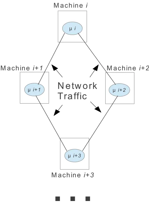
Fig. 2.1.Software based simulator architecture
2.3. Hardware Simulators. In the world of P System Simulators there have also been several attempts at using computer hardware for example [1] (a comprehensive list can be found in [4] ), for simulating P Systems, arguably the most scalable being the use of GPGPU processing power. This approach harnesses the power of computer video cards’ computational power in simulating P Systems. The computational part of video cards is used to transform three dimensional data from a video game or CAD tool, into a displayable two dimensional image. Since most artefacts (elements to be displayed on the screen) can be computed independently, the processing unit of video cards essentially becomes a massively parallel computation infrastructure as to increase performance in rendering. This parallel computation of video cards has sparked the imagination of researchers as the number of FLOPS (Floating-point Operations Per Second) of a graphic card is orders of magnitude higher than standard general purpose processing units. Due to this trend, video card manufacturers have developed API libraries and architectural changes to better enable the use of graphic cards for general purpose parallel computing hence GPGPU ( General Purpose Graphics Processing Unit).
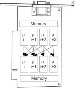
As with the software simulators, several different approaches have been tried but they are usually variants on the same theme. The GPGPU hardware is designed to enable high number of simulations threads (usually in the hundreds) which all execute in parallel. In the P System simulators each membrane is placed in an independent thread. Depending on implementation and type of P System different approaches have been used to implement membrane communication where the final objects in each membrane are somehow encoded to the memory of the video card. Each evolution of the P System consists of another run through the video card pipeline. Though many different optimizations and executions styles exists for the purposes of this article this basic definition will suffice for our exploration. In figure 2.2 we represent photographically the distribution of membranes cross different parallel pipes with the GPGPU device.
2.4. P system Testing. A P System by its definition has different primitives compared to classical pro-gramming languages. In standard testing theory we deal with conditional statements, lines of code, looping constructs and other such artefacts. A P system does not contain any such elements, and is constructed from rules in membranes acting upon objects. As such testing theory was adjusted to deal within these artefacts when attempting to test P systems. Most of the theory developed focused on the rules application (within a membranes) as it is the driving force within a P system. Two different methods were developed in testing the rules of a P system, namely simple rules coverage, and context dependent rule coverage. Significant effort has gone into creating methodologies for generating the test oracles. Usually these use one or more of these categories: Grammar based methods, Finite state machine based methods, model checking, and derivation tree based methodologies [7]. Initially the most promising methodology was through the use of model checking software such as NuSMV [9] and SPIN [10]. The approach rewrites a P system as a Kripke structure represen-tations, and uses a series of LTL (Linear Temporal Logic) formulas to extract test sets. This initial approach was very effective in developing test oracles but was quite limited in its ability to scale. SPIN was also used in a similar manner where the P System was implemented in Promela (the modelling language of SPIN) and much better results were achieved, though this approach was limited to the capabilities of a single machine. The combination of existing theory of X-machines testing theory and P Systems was also attempted [11] which also gave methods of formally testing P Systems. All of these approaches though very innovative, were at times limited in their ability to leverage existing high powered parallel simulators such as those mentioned in the introduction. The technique which is possibly the most adequate for leverage existing hight powered P System simulators is the computation tree mechanism. Before we look at the different testing techniques we will first example the computation tree (the framework used in developing test oracle).
Fig. 2.2.GPU based simulator architecture
property that enable very natural modelling of physical systems. At the same time this explosion in the size of a derivation tree is also the motivating factor for using high performance computing (the parallel simulators) in dealing the non trivially sized P Systems.
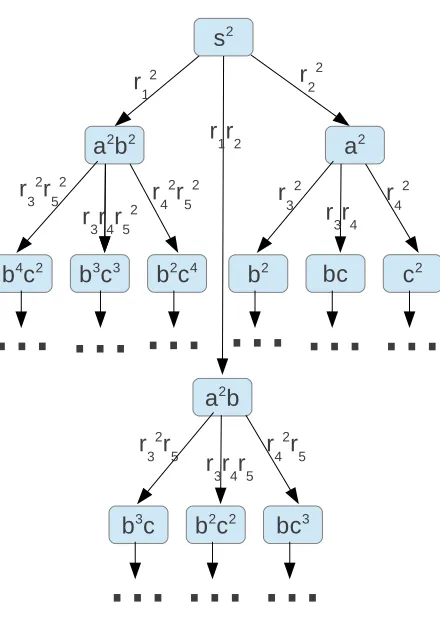
2.4.2. Simple Rule Coverage. Simple Rule Coverage [9] consists of verifying the application of each individual rule in the P System. To have complete simple rule coverage every single rule in every membrane must be applied at least once, with the entire evolution of the P system. To develop a test oracle there are several methodologies including using formal verifiers, though for the propose of this article the most applicable method uses computation trees. Traversing the computation tree (in either a breath or depth first manner) would enable the extraction of a test oracle as the tree contains both the rule application and the resultant multisets. To offer an example we have the P System given in the preliminaries section. Simple rule coverage would require the application of all rules from r1 to r5 at least once, hence the following executions of the
P System would offer complete simple rule coverage. The test vectors are displayed in the following format: multiset { with these rules applied }. A → is used to define the resultant configuration after applying the defined rules.
s2{r1r2} →a2b{r3r4r5} →b2c2
Fig. 2.3.P system Computation Tree
viable, though may take more time to execute as both test vectors must be executed to achieve simple rule coverage.
s2{r2} →2 a2{r24} →c2
s2{r21} →a2b2{r32, r 2
5} →b4c2
2.4.3. Context Dependent Rule Coverage. Context Dependent Rule Coverage [9] is a more complete test mechanism for P Systems, as it requires the testing of all possible rules in every possible context. Usually sequential steps in the simulation of P Systems would have some rules applied in sequential steps. For example in step 1 rule 1 is applied and in step 2 rule 3 is applied. Rules (1,3) would be a context dependent rule coverage pair which would need to be tested. All possible context dependent rule coverage pair them must be traversed by a simulator to achieve complete context dependent rule coverage. Context dependent rule pairs can be calculated without simulation of the P System, directly from the membrane and rule structure, and the test oracle again can be discovered from traversing a computation tree. For a discovery perspective this type of testing is much more difficult as it requires historical context and can not be calculated on the fly as simple rule coverage can. Context dependent rule coverage requires a system by which historical data is store to compare to current state. It is the comparison to historical data which enables use to determine context and is the most difficult element to augment on P system simulators. We can again look at an example of finding context dependent rule coverage test sets for the example P system in the preliminaries. If we look at r1 and
r2 we see there is not rule which produces thesobject required to apply those rules, hence there is no context
we see that bothr1 and r2 can generate this context, hence we have context dependent pairs (r1, r3), (r2, r3).
We continue this process with the rest of the rules and discover additional rule pairs: (r1, r4), (r2, r4), (r1, r5),
(r3, r5). We can do walks of the computation tree to discover the following test vector which would guarantee
context dependent rule coverage testing.
s2{r1, r2} →a2b{r3, r4, r5} →b2c2{r25} →b2c4
We can see by the more complicated test set required that Context Dependent Rule Coverage is a more stringent rule coverage criteria. It is important to note that although only consecutive rows (steps) in the computation tree are required to discover context dependent rule pairs, the entire tree is required when extracting the test oracle. A test oracle is required to start from the initial configuration of the system, hence a path (in the computation tree) from the currently discovered context dependent rule pair to the root note needs to be maintained. As there is no way of determining which paths will be useful until they are explored the full computation tree mush be maintain until all test oracle are discovered.
3. Augmenting Software Simulators for Testing. When looking at software simulators we see that most, if not all implementations, do not have provisions for neither scoring nor backtracking for one very simple reason. Both scoring and backtracking require the storage of at least meta data describing the evolution process and the cost (CPU and memory) of storing the information would impede performance, hence such data is not stored. For the use of these simulators in a testing context this storage of data is no longer optional and a method needs to be found which would impact least the performance of the system. Most critical for performance is the networking, as it has already been identified and a bottleneck for this type of simulators, hence any augmentations should be designed to produce the minimum amount of network traffic.
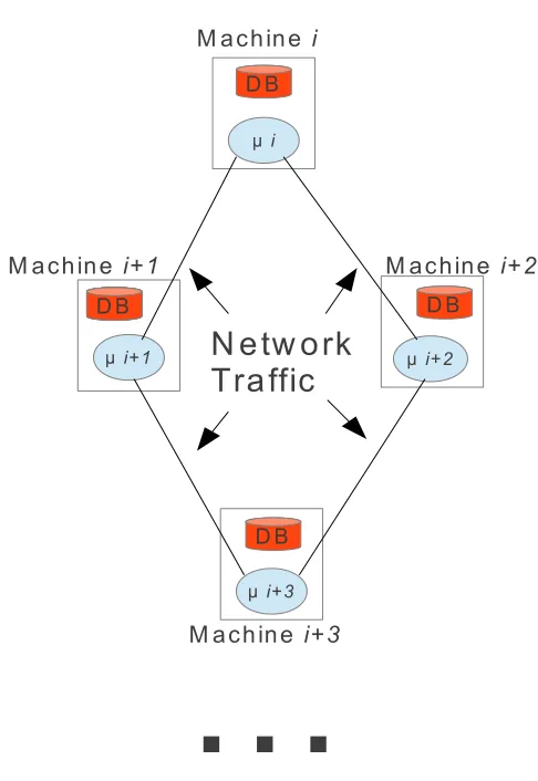
For data storage the standard would be some type of database technology but a typical RDBMS would require all data from each server in the simulation cluster to the shipped to central database which would put significant pressure on the already overburdened network. The use of local storage where each server in the simulation cluster stores data / metadata locally would be a great solution for the networking bottleneck but queering this data in a holistic manner would then be difficult as there is no link between the individual server’s data. The most suitable solution would be a hybrid approach potentially a NoSQL database.
NoSQL databases are a new breed of database technologies coming out of the Web 2.0 sphere which take advantage of distributed computing to scale in both data size and simultaneous transactions. These databases usually run in distributed mode where the storage of multiple physical servers is used simultaneously as a persistence layer. For more information please read the description in [8]. This database would be installed on every single server in the simulation cluster, which would allow for data storage operations to execute directly on the same server. At the same time when cross membranes queries are required the database can perform network based queries where all of the servers are interrogated and a holistic view is provided.
The process of using the distributed clusters for the discovery would be as followed:
1. Load the test sets which need to be discovered into the NoSQL database, ensure each local storage server has information pertinent to which will be simulated on that server.
2. Begin the simulation process on all of the servers, where a small background process scores the discovered test scenarios.
3. Stop the simulator when all off the test scenarios have been discovered on all of the servers.
4. Perform complex queries on the NoSQL database to extract the test oracles based on all of the data stored on each of the servers.
Figure 3.1 has a pictographic description of the architecture which could be used.
Fig. 3.1.Software based simulator architecture which would be usable for testing
There are two possible ways by which to augment the simulator for software testing.
1. Implement the testing requirements (backtracking and scoring) right on the hardware device itself 2. Move the results of the hardware simulator to the host system where they can be analysed for the
required test oracles
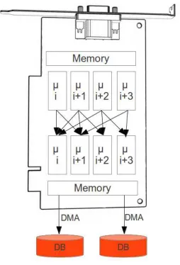
The poorly optimized branch instruction would make approach 1 significantly impede the performance of the simulators hence approach 2 would be preferred. To reduce the impact of the low bandwidth return pipe, DMA (Direct Memory Access) interface to the GPU memory can be used. This will enable the fastest possible retrieval of data from the graphical device while reducing the impact on the CPU. The graphic card memory is usually used as a ring buffer, a feature which can be exploited for the data movement. Data is written by the simulator to memory and a read pointer pulls data to the main system. The read pointer can be far behind the write pointer without impact on data consistency as long as unread data is not overwritten. This will enable a certain amount of latency in reading while still allowing the simulator to run at full speed.
Once the data is pulled to the host system (possibly into a database), the same algorithms used for the software based simulators to extract test vectors and their oracles can be used. Given that data is moved from the video card into a database, it is theoretically possible to use the database as a synchronization service for chaining multiple GPUs together and create a GPU compute cluster. This is possibly to be explored in a future article.
Fig. 4.1.GPU based simulator architecture which would be usable for testing
simulator though a different approach would need to be used for extracting data from the memory of the system. This extraction of data will be based on the type of hardware used and possible interface options. We can see in Figure 4.1 a conceptual diagram of what the architecture of such a system would look like.
tree for any general purpose simulator. The interface should contain the following interfaces as to enable easy hook-in for established simulators.
1. Store Configuration possibly with ID for easy identification (Configuration ID) 2. Add Edge from Configuration (Configuration ID, Edge)
3. Add Target Configuration (Source ID, edge, Target ID) 4. Get all Configurations at a level (level number)
5. Get root configuration
6. Get all child configurations (Configuration ID) 7. Get parent configuration (Configuration ID)
Using these very primitive functions a execution tree can be created using any simulator which can call this interface. As well walks of the tree can be performed to compute test vectors and test oracles for simple rule coverage and context dependent rule coverage.
6. Preliminary Results. To see what scaling possibilities are available with this architecture we would need to look at some testing results of an augmented P System simulator. Although a fully generic NoSQL database interface which can snap onto any simulator is still in development, we do have results of a NoSQL database attached to a Hadoop based simulator of P Systems. The tests below used a very simple P system designed to allow for maximal use of the parallel architecture of Hadoop. The test looked at how many nodes in a computation tree could be added into the database, at each level of the tree.
Tree Level Number Of Nodes Duration
2 14 24s
3 196 26s
4 2 744 36s
5 38 416 48s
6 537 824 4m 13s
7 7 529 536 54m 18s
The cluster used for these experiments was composed of 12 machines each with a simple core 2 duo processor 4 GB of RAM and single SATA hard disk, with simple 100 MB unmanaged network connecting the machines. It is also important to note the time gating factor was the simulator and not the database, but these results go give an idea of scaling possibilities.
To see even large computation trees we can look at the article [6] where even larger computation tree was developed. In one experiment done for the article it was attempted to create a very large computation tree. These results used the same set-up as the previous experiments though there were 16 machines in the cluster and membrane communication was enabled. The number of nodes created in an experiment was:
Number Of Nodes Storage Space Executon Time
65 471 486 84.9 GB 16.54 hrs
77 186 334 105.4 GB above + 5.52 hrs
This execution was again quite small compared to the possibilities of scaling. To get an idea of what a NoSQL database can do, we can look at published performance results for Oracle’s NoSQl Database. There we see close to 100, 000 inserts per second into a 12 node cluster (though the nodes were Dual Xeon multi hard disk systems) [8]. The scaling results are also very high, possibly into the petabyes of data architecture.
already exists an implementation which uses Hadoop to generate a derivation tree which is stored in a NoSQL database, derivation trees which can be hundreds of millions of nodes in size. Further as part of the same project distributed architecture is used to walk the computation tree and discover the P System test oracles. Future work will now concentrate on extending the developed application to a more generic in interface, as to allow any simulator to insert into the NoSQL database and inherently build a computation tree. This will allow for explicit testing of all architectures described in this article and allow for a quantitative comparison of the different schemas. Further we will also look at possible hybrid implantations of the simulators mentioned in this article to find the most viable solution for scaling to large P System in our simulation and testing effort.
Acknowledgement. This work was partially supported by a grant of the Romanian National Authority for Scientific Research, CNCS–UEFISCDI, project number PN-II-ID-PCE-2011-3-0688.
REFERENCES
[1] L. Ferndez, V. J. Martatinez, F. Arroyo, and L. F. Mingo. A hardware circuit for selecting active rules in transition p systems. In SYNASC, pages 415-418, 2005.
[2] G. Ciobanu and G. Wenyuan. A P system running on a cluster of comput- ers. In Lecture Notes in Computer Science, WMC 2003, pages 123-150. Springer-Verlag, 2004.
[3] A. Syropoulos, L. Mamatas, P. C. Allilomes, and K. T. Sotiriades. A dis- tributed simulation of transition P systems. In Workshop on Membrane Computing, pages 357-368, 2003.
[4] M. A. Martinez-del-Amor: Accelerating Membrane Systems Simulators using High Performance Computing with GPU. PHD thesis University of Seville (2013).
[5] G. P˘aun: Computing with membranes. Journal of Computer and System Sciences 61(1), 108-143 (2000). [6] A. Ciobanu, F. Ipate Using Big Data technologies with P systems CMC14 proceedings pages 95-116.
[7] M. Gheorghe, F. Ipate. Testing based on P systems - an overview. Proceedings of the Eleventh International Conference on Membrane Computing (CMC11), Jena, Germany, August 2010, pp. 7-10, ProBusiness Verlag, Berlin. Lecture Notes in Computer Science, vol. 6501, pp. 3-6, Springer, 2010.
[8] https://blogs.oracle.com/charlesLamb/entry/oracle_nosql_database_performance_tests/.
[9] F. Ipate, M. Gheorghe, R. Lefticaru. Test generation from P systems using model checking. Journal of Logic and Algebraic Programming, 79(6): 350-362. Elsevier Science Inc, 2010.
[10] F. Ipate, R. Lefticaru, C. Tudose. Formal verification of P systems using SPIN. International Journal of Foun-dations of Computer Science Vol. 22, Nr. 1/2011.
[11] T. Balanescu, M. Gheorghe, F. Ipate. Combined power of X-machines and P systems. Analele Universitii Bucureti, Informatic, Vol. LVIII, pp. 35-48, 2009.
[12] G. P˘aun, G. Rozenberg, A. Salomaa : The Oxford Handbook of Membrane Computing. Oxford University Press (2010).
Edited by: Dana Petcu
Received: Sep 1, 2013