Available Online at www.ijpret.com 1748
INTERNATIONAL JOURNAL OF PURE AND
APPLIED RESEARCH IN ENGINEERING AND
TECHNOLOGY
A PATH FOR HORIZING YOUR INNOVATIVE WORKRAIN TECHNOLOGY
SHEETAL S. DHOLE1, PROF. V. K. LIKHITKAR2, DR. H. R. DESHMUKH3
1.Student of Master of Engineering in (CSE), IBSS college of Engineering and Technology, Amravati, India. 2. Assistant professor Department of (CSE). IBSS College of Engineering and Technology, Amravati, India. 3. Head of the Department of (CSE), IBSS College of Engineering and Technology, Amravati, India.
Accepted Date: 05/03/2015; Published Date: 01/05/2015
Abstract: This review paper is focused on evolution of RAIN technology, its requirement, architecture, components and its implementation on different topology. Rain was developed to overcome the problem of cloud computing and current existing problem on accessing internet. Rain technology provides an efficient method for fault tolerance in different topology. Rain was developed to overcome the problem of cloud computing and current existing problem on accessing internet. Rain technology provide an efficient method for fault tolerance in different topologies which is not covered by cloud computing. Whenever the system becomes distributed, the issue of fault tolerance becomes an important consideration. Rain technology makes the addition of new nodes in different type of topology much easy and convenient without disturbing the already existing structure of topology. For Especially in star topology, if the host node gets failed, the rest of the entire network also fails. So this failure or fault can be easily recovered with the help of rain technology. Secondly, addition of new node in mesh topology and ring topology is difficult, In our research we will study how the problem of addition of new nodes in already existing structure can be eliminate. In different topology named as Ring, Bus, Mesh, Star, Tree and Hybrid topology ,Fault Tolerance can be handled by rain technology, this feature was not included in cloud computing. Whenever we send the messages from one node another node, there are multiple processors in between of sender and Receiver, if any processor fails in between, the message still continues to travel and will reach the desired destination. The main purpose of rain technology was to overcome the existing problems on the internet. It acts as component that stores data across distributed processors and retrieves it even if some of the processors fail. Rain computing is a miracle for those devices that do not have enough processing power to handle the amount of traffic they receives. Rain Technology provides feature of replacing a faulty node by a healthy node without breaking the information flow.
Keywords: RAID, SATA, Hot-swap, SNOW, Cluster computing, Data storage, Cloud computing, 1U Sever.
Corresponding Author: MS. SHEETAL S. DHOLE
Access Online On:
www.ijpret.com
How to Cite This Article:
Sheetal S. Dhole, IJPRET, 2015; Volume 3 (9): 1748-1761
Available Online at www.ijpret.com 1749
INTRODUCTION
The reliable array of independent nodes (RAIN) project is a research collaboration between Caltech’s Parallel and Distributed Computing Group and Jet Propulsion Laboratory’s Center for Integrated Space Microsystems, in the area of distributed computing and data storage systems for future space born emissions. The goal of the project is to identify and develop key building blocks for reliable distributed systems built with inexpensive off-the –shelf components. Rain technology has evolved over the disadvantages of cloud computing and was developed by the California Institute of technology, in collaboration with NASA’s Jet Propulsion laboratory and the DARPA. The name of the original research project was RAIN, which stands for Reliable Array of Independent Nodes. The RAIN research team in 1998formed a company called Rain finity. RAIN is also called channel bonding, redundant array of independent nodes, reliable array of independent nodes, or random array of independent nodes. Basically Rain technology has come up with the different network solutions over the internet such as nodes failure, traffic congestion, link failure, data lost. It is a cluster of nodes linked in a network topology with multiple interfaces and redundant storage. It is an implementation of RAID across nodes instead of across disk arrays. RAIN is used to increase fault tolerance .RAIN can provide fully automated data recovery in a local area network or wide area network even if multiple nodes fail. A browser-based, centralized, secure management interface facilitates monitoring from a single location. There is no limit to the number of nodes that can exist in a RAIN cluster. New nodes can be added, and maintenance conducted, without incurring network downtime. There is no limit to the number of nodes that can exist in a RAIN cluster. New nodes can be added, and maintenance conducted, without incurring network downtime.
2. RAIN COMPONENT
RAIN is an open architecture approach that combines standard, off-the-shelf computing and networking hardware with highly intelligent management software. RAIN-based storage and protection systems consist of following component:
A. Rain Nodes
Available Online at www.ijpret.com 1750
B.IP-based Internetworking
RAIN nodes are physically interconnected using standard IP-based LANs, metropolitan-area networks (MAN) and/or WANs. This lets administrators create an integrated storage and protection grid of RAIN nodes across multiple data centers. With MAN and WAN connectivity, RAIN nodes can protect local data while offering off-site protection for data created at other data centers.
C. Rain Management Software
This software lets RAIN nodes continuously communicate their assets, capacity, performance and health among themselves. RAIN management software can detect the presence of new RAIN nodes on a new network automatically, and these nodes are self-configuring.
D. Storage Component
In a RAIN-based storage system, each RAIN node regularly checks all its own files. The combination of hundreds of RAIN nodes forms a powerful parallel data-management grid. When file corruption is detected, the associated RAIN node initiates a replication request to all other RAIN nodes, which verify their own replicas and work collectively to replace the defective file.
E. Communication Component
There is no limit to the number of nodes that can exist in a RAIN cluster. New nodes can be added, and maintenance conducted, without incurring network downtime, A communications component that creates a redundant network between multiple processors and supports a single, uniform way of connecting to any of the processors.
F. Computing Component
A computing component that automatically recovers and restarts applications if a processor fails. RAIN technology was able to offer the solution by minimizing the number of nodes in the chain connecting the client and server, RAIN technology provides the novel feature of replacing a faulty node by a healthy one thereby avoiding the break in information flow.
3. ARCHITECHURE
Available Online at www.ijpret.com 1751
Figure 3.1: Architectures of RAIN Technology [1]
A. Reliable transport
Reliable transport ensures the reliable communication between the nodes in the cluster. This transport has a built-in acknowledgement scheme that ensures reliable packet delivery. It transparently uses all available network links to reach the destination. When it fails to do so, it alerts the upper layer, therefore functioning as a failure detector. This module is portable to different computer platforms, operating systems and Networking environments.
B. Consistent global state sharing protocol
This protocol provides consistent group membership, optimized information distribution and distributed group-decision making for a RAIN cluster. This module is at the core of a RAIN cluster. It enables efficient group communication among the computing nodes, and ensures that they operate together without conflict.
C. Always-On-IP
Available Online at www.ijpret.com 1752 physical node fails in the cluster, its virtual IP will be taken over by another Healthy node in the cluster.
D. Local and Global Fault Monitors
Fault monitors track .the critical resources within and around the cluster: network connections, on a continuous or event-driven basis. They are an integral part of the RAIN technology, guaranteeing the healthy operation of the cluster.
E. Secure and Central Management
This module of Rain Technology offers a browser-based management GUI for centralized monitoring and configuration of all nodes in the RAIN clusters. The central management GUI connects to any node in the cluster to obtain a single-system view of the entire cluster. It actively monitors the status, and can send operation and configuration commands to the entire cluster.
4. NOVEL FEATURES OF RAIN
The RAIN project incorporates many novel features in an attempt to deal with faults in nodes, networks, and data storage.
A. Communication
As the network is frequently a single point of failure, RAIN provides fault tolerance in the network through the following mechanisms
1) Bundled Interfaces: Nodes are permitted to have multiple interface cards. This not only adds fault tolerance to the network, but also gives improved bandwidth.
2) Link Monitoring: To correctly use multiple paths between nodes in the presence of faults, link- state monitoring protocol is used that provides a consistent history of the link state at each endpoint.
Available Online at www.ijpret.com 1753
B. Group membership
A fundamental part of fault management is identifying which nodes are healthy and participating in the cluster. If any node from group fails, its work is immediately handled by another member from group. Strong group management of Rain Technology gives the different feature of load sharing, handle network congestion and efficiently handle node or link failure.
C. Data Storage
Fault tolerance in data storage over multiple disks is achieved through redundant storage schemes like RAID (Redundant array of independent disk). If any node or disk fails then redundant data stored at another node provide the information of failed node.
5. OBJECTIVES
• While data transmission from sender to host, if any token is lost it can be regenerated with the help of rain technology.
• If any nodes in the complete topology segment fails, so it can be repaired and added again in the already existing technology without disturbing the network. While the node is undergoing the repair stage, the other nodes keep on working. Failure will not affect the rest active node.
• By applying the switches in between of different node, data availability factor can best rengthens, Even if the data is lost from one node, it can be recovered from other nodes.
• Rain technology helps in building the structure of topology in such a manner that it minimizes the number of nodes and removes the extra nodes. It is able to provide the solution by minimizing the total number of nodes in network between client and server.
• As the total number of nodes is minimum, so the data transmission time will also be reduced from source node to destination node. Secondly, delay factor will also be reduced and data can be transmitted within less period of time.
SOLUTION
6.1 Star Topology
Available Online at www.ijpret.com 1754 other peripheral) is connected to central node called hub or switch. The switch is the server and the peripherals are the clients.
Fig: 6.1.2 Structure of Star Topology
6.1.3Problem in Star Topology
• In star topology, if the central hub fails all the corresponding nodes also fail and theentire network stops working.
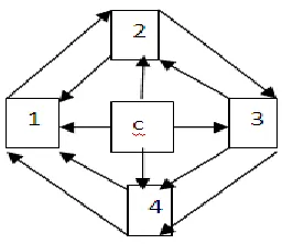
6.1.4 Solution through Rain Computing
As shown in the diagram, following is the solutionfor the Star topology; all the corresponding nodes are attached in such a manner that if one node fails, its data content are available on the adjacent nodes. Similarly if the central node fails, the adjacent nodes remain active due to adjacent nodes sharing. This solution will strengthen the data availability as a strong component and the system will work as a global environment.
Available Online at www.ijpret.com 1755
Faults: In above problem, the critical situation occurs when the C node fails, therefore all thecorresponding nodes are connected via switch so that they can share the resources. The replica of the data content of all the nodes are provided in the volatile segment of each node processors.
Traffic Congestion: If the data has to be shared from node 1 to node 2, and the switch between them fails, then the corresponding option is available following path1-4-3.Similarly, if the central node fails, then the data can be available from the corresponding nodes with the help of switch.
Repair: If node 1 is down for repair, the rest of the network is still active .Node 2 and Node 4 will not be affected at all. Similarly, if the central node is taken out of the structure, the rest network still works.
6.2 RING TOPOLOGY
6.2.1 A ring network is one in which every node is connected to other adjacent nodes and forms a ring like structure. Data travels from node to node, with each node along the way handling every packet. FDDI networks overcome this vulnerability by sending data on a clockwise and a counter clock wisering: in the event of a break data is wrapped back onto the complementary ring before it reaches the end of the cable, maintaining a path to every node along the resulting "C-Ring.
6.2.2 Ring Topology Structure
6.2.3 Problems in Ring Topology
Available Online at www.ijpret.com 1756 • Addition of new node is not easy, In fact Moves, adds and changes of devices can affect the network.
6.2.4 Solution through Rain Computing
As shown in the diagram, the fault has occurred at two joints and it is going to affect the adjacent nodes. So, the solution to this problem is provided by connecting the nodes in such a manner so that if any nodes fail, its solution is always available with the other subsequent nodes.
Fig 6.4.5 Problem in the Ring Topology
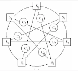
As shown in the diagram below, the nodes are connected to the switches that are connected to themaximum distance. So in the circle the maximum distance is the diameter only. All the nodes areconnected to other node at full scale diameter with switch in between of them.
Available Online at www.ijpret.com 1757 Diameter Solution: Here the nodes are connected toswitches that are maximum distance apart from eachother which is diameter in a ring. Diameterconstruction with nodes of degree 2 connected to nswitches of degree 4 can tolerate 3 fault withoutportioning the network which is optimal.
6.3 BUS TOPOLOGY
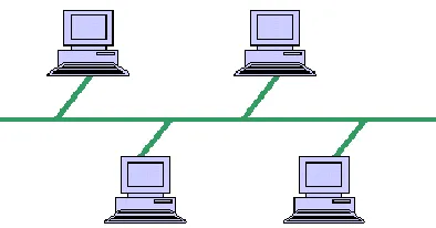
Bus networks are the simplest way to connect multiple clients. This topology is a multipoint configuration. One long cable acts as a backbone to link all the devices in the network. Nodes are connected to the bus cable by drop lines and cable. All the nodes are connected to bus that runs through the network. Drop line is a connection running between the devices and the main cable. As a signal travels along the backbone. Some of its energy is transformed into heat, Signal becomes weaker and weaker.
Fig 6.3.1 Structure of Bus Topology
6.3.2 Disadvantages
Reconfiguration, fault isolation and installation of new devices tend to be difficult since the network is designed to be most efficient during installation. A fault along the shared communication line stops all transmissions in the network.
Available Online at www.ijpret.com 1758
6.3.4 Solution
We know that in Bus topology, the main working element is backbone or the intermediate bus channel placed as transfer mode between all the nodes. So the switches can be placed in the backbone. In fact multiple switches can be placed in the backbone. The only problem with this structure is that is the backbone fails, it has to repair because switch has been made integral component of the backbone. Data availability and data persistence is the major benefit in this solution.
6.4 MESH TOPOLOGY
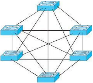
Mesh networking is the one in which every device has a dedicated point to point link to every other device. By dedicated link means that the link carries traffic only between the device it connects .A fully connected mesh network therefore has n (n-1)/2 physical channels to link n devices. To accommodate that many links, every device on the network has n-1 input/output ports. A mesh network can be designed using a flooding technique or a routing technique. When using a routing technique, the message propagates along a path, by hopping from node to node until the destination is reached.
Fig 6.4.1 Structure of MESH Topology
6.4.2 Disadvantages
• If the network covers a great area, huge investments may be required due to the amount of cabling and ports required for input and output devices. It is a rare choice of a network connection due to the costs involved.
Available Online at www.ijpret.com 1759
6.4.3 Solution
The problem in the mesh topology can be solved by the diametric solution. The nodes are kept distance apart and the link is established at minimum distance. In that link, the switch is placed to handle the network. If the structure of the Mesh topology is very big, then multiples nodes can be placed in that link. Although point to point link is the other solution where each point is created in between of the nodes to share the data.
Fig 6.4.4 Solution to Mesh Topology
4.5 HYBRID TOPOLOGY
A hybrid is a combination of two or more basic network topologies, such as a star-bus, star-ring, or tiered topology. In a hybrid topology, central and distributed topologies are combined to meet the needs.
6.5.1 Structure of Hybrid Topology
6.5.2 Disadvantages of Hybrid Topology
• Complexity of Design: One of the biggest drawbacks of hybrid topology is its design.
Available Online at www.ijpret.com 1760 • Node Failure: As we can see in above structure that hybrid is a combination of different topologies, so the node failure sometime may be very critical or sometimes it will be nominal that can be recovered easily.
6.5.3 Solutions
There is no fixed solution of Hybrid topology failure as it is huge structure topology with a combination of multiple switches in between. As already different topologies with different solution are connected in hybrid topology so when combined together and work as hybrid segment, there are less chances of node failure. Even if the node or link fails, the very first step will be to trace out the path where the failure has occurred. Individual solution of each topology helps in recurring the hybrid topology faults.
7. ADVANTAGES
1. This technology when applied in the different topologies will increase the robustness of each topology.
2. All nodes will be active throughout the topologies and can handle the load balancing.
3. RAIN Technology is the most scalable software cluster technology for the Internet market place today.
4. There is no limit on the size of a RAIN cluster.
5. All nodes are active and can participate in load balancing. New node can be added into the cluster to share load balancing.
6. This software only technology is open and highly portable.
7. A part of the cluster can be taken down for repair whereas the others can continue working.
8. There is no concept of master-slave or host-node relation. Either all hosts become nodes or all hosts become nodes.
9. It is highly efficient in load balancing and traffic congestion control.
Available Online at www.ijpret.com 1761 1. As the rain technology requires placement of switches in between of structure, so it becomes little expensive to add on the switches.
2. Secondly, Installation and configuration is time consuming and requires maintenance also.
3. Although if the node of the topology fails, it will not disturb the topology completely as mentioned above but if the switch fails, it affects the network partially and switch has to be repaired as early as possible.
9. FUTURE CONCLUSION
By the end of this paper, it can be concluded that rain technology is an overcome solution for the disadvantages of Cloud Computing, Rain Technology proven to be the stronger technology when compared to Cloud computing .Secondly Rain technology can be embedded into various layer of OSI model which will definitely removes the problem occurring at different layers such as link break up, point to point failure, traffic congestion, load balancing. Rain technology at data link layer will help in sequencing and time to time delivery of data packets. Similarly, it will also handle the traffic congestion, packets sequencing at both ends. By the use of Rain Technology, each node in the network will not be dependent on other nodes. It is going to decrease the node independence factor rate the management software transmits tasks to various computers and, in the event of a failure, will retry the task until a node responds. Besides Cloud computing and Rain computing, SNOW technology will shortly come in evolution, Snow Technology (Strong network of web servers) is a cluster of server’s network that provides a highly robotic system. This technology will enhance the server performance.
10. REFERENCES
1. Harinder Kaur, “Cloud Computing: Rain Cloud Computing: Rain Cloud System”,
InternationalJournal of Emerging Technology and Advanced Engineering, Volume 2, Issue 10, October 2012.
2. V. Bohossian et al., “Computing in the RAIN: Reliable Array of Independent Nodes,” IEEE Trans. Parallel and Distributed Systems, vol. 12, no. 2, Feb. 2001, pp. 99-114.
3. http://www.computerworld.com.au/article/120893/rain_architecture_scales_storage
4. http://en.wikipedia.org/wiki/Reliable_array_ofindependent_nodes.
![Figure 3.1: Architectures of RAIN Technology [1]](https://thumb-us.123doks.com/thumbv2/123dok_us/8744644.1747020/4.612.198.413.82.281/figure-architectures-of-rain-technology.webp)