Department of Information Engineering and Computer Science ICT International Doctoral School
Efficient Motion Planning for Wheeled
Mobile Robotics
ADVISOR
PH.D. CANDIDATE
Prof. Luigi Palopoli
Dr. Paolo Bevilacqua
University of Trento
University of Trento
CO-ADVISOR
Abstract
Nowadays, the field of wheeled robotics is undergoing an impressive growth and development. Different hardware and software components are being developed and applied in various contexts, including assistive robotics, industrial robotics, automotive, ...
Motion Planning is a fundamental aspect for the development of autonomous wheeled mobile robots. The capability of planning safe, smooth trajectories, and to locally adjust them in real-time to deal with contingent situations and avoid collisions is an essential requirement to allow robots to work and perform activities in public spaces shared with humans. Moreover, in general, efficiency is a key constraint for this kind of applications, given the limited computational power usually available on robotic platforms. In this thesis, we focus on the development of efficient algorithms to solve different kind of motion planning problems. Specifically, in the first part of the thesis, we propose a complete planning system for an assistive robot supporting the navigation of older users. The developed planner generates paths connecting different locations on the map, that are smooth and specifically tailored to optimize the comfort perceived by the human users. During the navigation, the system applies an efficient model to predict the behaviours of the surrounding pedestrians, and to locally adapt the reference path to minimise the probability of collisions. Finally, the motion planner is integrated with an “high-level” reasoning component, to generate and propose complete activities, like the visit to a museum or a shopping mall, specifically tailored to the preferences, needs and requirements of each user. In the second part of the thesis, we show how the efficient solutions and building blocks developed for the assistive robots, can be adapted and applied also to a completely different context, such as the generation of optimal trajectories for an autonomous racing vehicle.
Acknowledgments
Contents
1 Introduction 1
1.1 Assistive Robotics . . . 2
1.2 Automotive . . . 6
1.3 Structure of the Thesis . . . 8
1.4 Scientific Contributions and List of Publications . . . 9
2 Background 11 2.1 Motion Planning Definitions . . . 11
2.2 Motion Planning Algorithms . . . 13
3 Related Work 16 3.1 Motion planning in static environments . . . 16
3.2 Socially acceptable navigation in human populated environments . . 18
3.3 Activity Planning: linking high and low-level planning . . . 20
3.4 Time-optimal trajectory planning for racing cars . . . 21
I
Assistive Robotics Applications
24
4 Clothoid Curves 29 4.1 Computational Issues . . . 305 Motion Planning 38 5.1 General Overview . . . 38
5.2 Problem Statement . . . 39
5.3 Proposed Solution . . . 43
5.4 Experimental Validation . . . 49
6 Reactive Planning 56 6.1 General Overview . . . 56
6.2 Proposed Approach . . . 57
6.3 Pedestrian Modelling . . . 58
6.5 Experimental Validation . . . 71
7 Activity Planning 78 7.1 General Overview . . . 78
7.2 The Activity Planning Problem . . . 79
7.3 Proposed Approach . . . 81
7.4 Problem Formalisation . . . 83
7.5 Proposed solutions of the Problem . . . 86
7.6 Experimental Validation . . . 91
II
Automotive Applications
99
8 Trajectory Optimization on Clothoids 101 8.1 Model of the Vehicle . . . 1018.2 Optimal Trajectory . . . 103
9 Minimum Time Trajectory 107 9.1 General Overview . . . 107
9.2 Optimal Trajectory Planning Algorithm . . . 108
9.3 Experimental Validation . . . 109
10 Optimal Trajectory Replanning 114 10.1 General Overview . . . 114
10.2 Proposed Approach . . . 115
10.3 Experimental Validation . . . 120
11 Conclusions and Future Work 123 11.1 Assistive Robotics . . . 123
11.2 Automotive Applications . . . 125
11.3 Future Work . . . 125
List of Figures
1.1 Population Pyramid Trend . . . 3
1.2 The FriWalk robotic walker . . . 5
1.3 The Roborace Robocar . . . 7
2.1 The motion planning problem . . . 13
4.1 The clothoid arc . . . 30
4.2 Clothoid Spline approximation with triangles and AABBtrees . . . 36
5.1 The FriWalk reference system . . . 40
5.2 I-RRT* search tree, and interpolating clothoid spline . . . 52
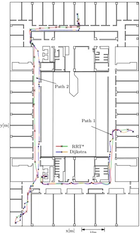
5.3 Experimental validation of the motion planning for assistive robotics: paths comparison . . . 53
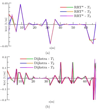
5.4 Experimental validation of the motion planning. First comparison of the curvature profiles . . . 54
5.5 Experimental validation of the motion planning. Second comparison of the curvature profiles. . . 55
6.1 Sensing sytem on theFriWalk . . . 57
6.2 Force decomposition in the Headed Social Force Model . . . 60
6.5 Short-horizon approximation of HSFM trajectories . . . 63
6.6 Intersection of walker and pedestrians clothoid “tunnels” . . . 67
6.7 The velocity diagram . . . 68
6.8 Local re-planning scheme . . . 71
6.9 Simulative validation of the reactive planner . . . 72
6.10 Simulative validation of the reactive planner . . . 74
6.11 Experimental validation of the reactive planner on the FriWalk . . 76
6.12 Experimental validation of the reactive planner on the FriWalk . . 77
6.13 Photos of the reactive planner running on the FriWalk . . . 77
7.1 The activity planner framework . . . 82
7.2 Example of simulated trajectories . . . 83
7.4 Graph layout adopted for the experimental validation . . . 90
7.5 Example of the output of the activity planner on a real museum . . 92
7.6 Replanning of an activity in a realistic scenario . . . 93
8.1 Reference system for the car-like model . . . 103
8.2 Example velocity profile . . . 106
9.1 Portion of the search tree . . . 111
9.2 Example of the generated time-optimal trajectory . . . 113
9.3 Example of the generated time-optimal trajectory in the presence of an obstacle . . . 113
10.1 Track structure and adopted notation . . . 116
10.2 Example of global time-optimal reference trajectory . . . 121
1
Introduction
Nowadays, robotics and automation are undergoing an impressive growth and development. Their application encompasses an endless number of different contexts, from industrial automation, to assistive robotics, to automotive.
All these applications display a number of different challenges and open problems, regarding a large number of different research fields. Among them, a fundamental problem, common to all the various robotic applications, is the capability of the robot to move autonomously from a certain initial configuration, to reach a dif-ferent, given final configuration. To accomplish this task, the robot is required to automatically determine the sequence of movements, i.e. the trajectory, to follow, considering both environmental and physical constraints. While the formers depend on the obstacles in the environment and on the geometry of the robot, the latter are for example kinematic constraints (e.g. the impossibility to turn on the spot for a car-like vehicle).
The main objective of this thesis is the development of efficient motion planning algorithms, both to synthesise a global path, and to replan local modifications to apply on-the-fly in real-time to avoid collisions with unforeseen static and dynamic obstacles. We propose efficient approaches and solutions, all based on a set of common and characterising basic algorithms and techniques, composing a set of building blocks that are adequately adapted and combined together to solve the different problems at hand.
1.1. Assistive Robotics
• Assistive robotics: path planning with a careful consideration and optimiz-ation of the comfort and satisfaction perceived by the assisted user. Dynamic adjustment of the original path to avoid collisions and ensure a safe navigation in public spaces shared with other people.
• Automotive: synthesis of minimum time trajectories for autonomous racing vehicles.
1.1 Assistive Robotics
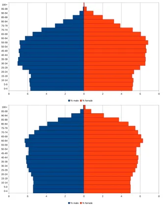
During the last decade, Western societies have experienced an increase in life expectancies and a simultaneous collapse of birth rates, that have brought to a rapid ageing of the population (in Figure 1.1 are shown the trend projections of population pyramids for the years 2020 and 2050). This phenomenon poses a fundamental challenge to modern societies: guaranteeing older adults an acceptable level of quality of life, while ensuring the economical sustainability of the National Health Systems. For these reasons, the concept of “active ageing” has been developed [1]:
Active ageing is the process of optimizing opportunities for health, participation and security in order to enhance quality of life as people age.
Indeed, “active” older people represent an important resource, as they provide a fundamental support to their families, peers and communities.
However, often a reduction of physical capabilities lead older adults to remain more and more time at home, causing isolation, depression, reduced fitness and increased mobility problems [1]. These in turn produce several detrimental effects: the lack of physical exercise leads often to the development of chronic diseases, such as diabetes. Moreover, reduced mobility increases the number of falls, that for older people represent an increasing cause of injury, requiring extended and costly periods of rehabilitation, and an higher risk of dying. Isolation, due to both the reduction of mobility, and the lost of family members and friends, leads to a decline of both physical and cognitive capabilities.
Chapter 1. Introduction 0-4 5-9 10-14 15-19 20-24 25-29 30-34 35-39 40-44 45-49 50-54 55-59 60-64 65-69 70-74 75-79 80-84 85-89 90-94 95-99 100+
8 6 4 2 0 2 4 6 8
% male % female
0-4 5-9 10-14 15-19 20-24 25-29 30-34 35-39 40-44 45-49 50-54 55-59 60-64 65-69 70-74 75-79 80-84 85-89 90-94 95-99 100+
8 6 4 2 0 2 4 6 8
% male % female
1.1. Assistive Robotics
impaired people, in order to increase their quality of life, and to give them the possibility of living and actively ageing in their own homes. Within the field of assistive robotics, a fundamental role is played by robots assisting the ambulation and allowing older adults to move autonomously. Indeed, these kind of robotic platforms represent an effective tool for older people to maintain an acceptable level of physical and social activity.
1.1.1 ACANTO
ACANTO is an European research project aiming to develop a smart assistive walker, the FriWalk. Its aim is to spur older users to maintain a good life style, and to regularly perform physical and social activities. The FriWalk is a tool providing a complete support to the user, during the execution of social and physical activities, and capable of assisting users with reduced mobility or cognitive capabilities. Its development is based on the adaptation of a standard rollator, with the addition of a sensing system to perceive the surrounding environment, and a set of actuators to provide it with navigation capabilities. In Figure 1.2 is shown a prototype of the smart robotic walker FriWalk developed within the ACANTO project.
In the next sections, we provide an overview of the main planning technologies and algorithms developed within the context of the ACANTO project, that are an important contribution of this thesis.
In addition to the planning system, other fundamental challenges, that are beyond the scope of this thesis, had to be solved for the development of a smart assistive rollator supporting the navigation of older users. In particular, we required a path following controller capable of sharing the responsibility for the guidance of the vehicle with the user [2, 3, 4, 5], and a robust indoor localisation system allowing the robot to know its exact position on the map [6,7, 8].
Planning System
The planning system is a fundamental software component for a navigation assistive robot. It is responsible for the planning of activities and tasks at different levels:
Chapter 1. Introduction
Figure 1.2: Example of the FriWalk robotic walker developed within the ACANTO project [9]
of points on the map. The generated paths should be comfortable to follow by older users with the support of the smart rollator. To determine the best path to follow, the planning system has to take into account user specific needs and preferences. To that hand, the ACANTO software infrastructure provides a shared knowledge base, containing all the information and profiles associated with each user. During the autonomous robot navigation, or while carrying an older user along the planned path, it may be necessary to apply local modifications, to overcome unforeseen events, e.g. the presence of pedestrians or obstacles hindering the original path. In case of users with reduced cognitive capabilities, or in situations where the robot is required to move autonomously between different locations on the map, the navigation system has to be able to apply local modifications to the reference trajectory, in order to avoid collisions. Thus, the global motion planner must be integrated with a reactive planner, capable of handling these scenarios.
1.2. Automotive
suggesting to the users a complete activity (e.g. visit to a museum, shopping mall, etc.), considering their requirements and preferences. This requires the capability of a “high-level”, abstract reasoning. Therefore, together with the low level motion planner, an high level planner is needed to determine the best sequence of activities to propose to the user, that will then be refined into a sequence of paths by the low level motion planning algorithm.
Over the years, many different approaches have been proposed to solve the motion planning problem for a robot. Given an initial and a final configuration, the motion planner finds an “optimal” trajectory connecting them, given the kin-ematic and dynamic constraints of the mechanical platform, and the map with all the obstacles that must be avoided. Also the problem of planning a sequence of generic, “high–level” actions to reach a specific goal, given a set of constraints and preferences, has been studied within the artificial intelligence community, and interesting solutions have been proposed.
However, for the implementation of a complete activity planning system for an assistive robot, the adoption of traditional motion planners is not sufficient, since they do not allow the modelling of tasks (e.g. which places to visit, how long, in which sequence) and “high–level” user constraints, essential to plan activities adequate for the user. On the other hand, high-level task planners generate abstract plans, composed by sequences of complex actions that cannot be directly used by the controller of the robot. Thus, the output of the task planner has to be refined into an executable plan. The refined plan consists in a path that must respect the same constraints and requirements of the original, abstract plan, but also the physical constraints of the robot.
1.2 Automotive
Chapter 1. Introduction
re-plan) in a short time a trajectory that satisfies all the dynamic constraints of the vehicle.
For all these reasons, different problems regarding different automotive applic-ations have been studied with increasing interest during the last years. One of them, becoming more and more relevant, is the automatic driving of cars at their limits, i.e. for autonomous racing. In Figure 1.3 is shown an example of a fully autonomous racing car, the Roborace Robocar.
Figure 1.3: The Roborace autonomous racing car: Robocar [10]
1.3. Structure of the Thesis
local replanning and modification of the global trajectory to overcome unforeseen obstacles.
1.3 Structure of the Thesis
The thesis is organised as follows. Chapter 2 introduces background knowledge and definitions on motion planning. Then, Chapter 3 presents a detailed literature review on the different kind of planning problems tackled by this thesis. Following, Chapter 4 contains a description of clothoid curves, a family of curves that we adopt as the basic motion primitives composing the paths that are generated by all the motion planning solutions proposed in this thesis. We propose a set of relevant problems involving these curves, together with efficient solutions for each of them. The remainder of the thesis is organised into two different parts.
The first part deals with the development of a complete planning solution for assistive robotics applications. In Chapter 5, we present an efficient solution for the generation of a smooth path specifically tailored to optimize the comfort perceived by the human during the navigation with the support of the assistive rollator. In Chapter 6, we develop a reactive planning solution, capable of locally adjusting the global reference path during the navigation, to avoid collisions with unforeseen static obstacles, and with the surrounding, moving pedestrians. To develop a solution both safe and efficient, we apply and approximate a model of human walking behaviour, the Headed Social Force Model, to determine the best local modification to apply, minimising the probability of collision while trying to minimise the amount of deviation from the original path. In Chapter 7, we show to integrate the global and reactive planning solutions developed in the previous chapters with a task planner providing high-level, abstract reasoning capabilities, to generate and propose to the user complete activities such as the visit to a museum or a shopping mall. These activities are synthesised considering the requirements, needs and preferences specific for each user.
Chapter 1. Introduction
of clothoid curves, explicitly considering a model of the vehicle with non–linear dynamics, aerodynamic drag effects, bounds on the control and constraints on the acceleration and speed. In Chapters 9 and 10, we show how to efficiently combine the solutions to the geometric and dynamic sub-problems, i.e. efficient generation of a path composed of clothoid arcs connecting two configurations, and efficient computation of the optimal manoeuvre, to generate the optimal trajectory on a given racing track, and to locally re-plan the reference trajectory in the presence of unforeseen obstacles along the way in real-time.
1.4 Scientific Contributions and List of Publications
This thesis proposes several contributions to the state-of-the-art in the field of motion planning, regarding different scopes and applications. In this section, we provide an overview of the main contributions of the thesis, and the list of peer-reviewed publications relevant for each of these contributions.
1. The development of an efficient motion planning solution for assistive robots, mainly focused on the optimization of the comfort perceived by the human users. This work has been presented and published at the IEEE Conference on Control Applications (CCA), 2016 [11].
2. The development of an efficient solution to reactively adjust the reference path during the navigation of an environment shared with other humans, through an efficient modelling of candidate human trajectories and an analytical computation of the probabilities of collision. This work has been presented at the IEEE International Conference on Robotics and Automation (ICRA), 2018, and has been published on the IEEE Robotics and Automation Letters (RA-L) [12].
1.4. Scientific Contributions and List of Publications
the assistive rollator. This work has been submitted to the IEEE Transactions on Industrial Informatics (TII), and is still undergoing the review process [13]. 4. The extension and adaptation of the efficient building blocks developed for
the motion planning for assistive robotics, and its application to determine the optimal trajectory for a racing vehicle on a track. Part of this work has been presented and published at the 55th IEEE Conference on Decision and Control (CDC), 2016 [14].
2
Background
In this chapter we will provide all the definitions and background knowledge relevant for this thesis.
2.1 Motion Planning Definitions
World The representation of the space where the robot and the obstacles lie. Usually, the world is either 2D (R2) or 3D (R3). The world is denoted by the symbol W.
Robot From the perspective of motion planning, a robot is seen as a physical body modelled geometrically, and that can be controlled via the motion plan. The pose of each joint composing the robot can be expressed using a set of parameters. The set of all the parameters determining the global state of the robot is known as its configuration. In general, a robot has associated some constraints limiting the set of feasible configurations. Notice that with this definition, a robot in terms of motion planning may not be an actual robot, but it could model any collection of moving bodies, and could be applied also for different applications, e.g. simulation of humans in virtual reality, molecules, etc. The rigid body associated with a robot is usually denoted by A.
2.1. Motion Planning Definitions
obstacles may models walls, furniture, etc. Usually, the set of rigid bodies associated with the obstacles are denoted by B1, . . . ,Bn.
Configuration Space In general, motion planners do not search a path directly in the world space W, but they work on the configuration space, that is the space of all the possible parameters for the different configurations of a robot. This space is usually denoted asC. Moreover, let W =Rm represents the world space, O ⊂ W the obstacle region, A(q)⊂ W the region of the world occupied by the robot while in configuration q∈ C, then we define:
Cfree ={q∈ C | A(q)∩ O =∅} and
Cobs =C \ Cfree
Path A path in the configuration space is a continuous function τ such that:
τ : [0,1]→ C
In addition, if τ lies entirely in the free configuration space, i.e.
τ : [0,1]→ Cfree then τ is a collision-free path
Motion Planning Problem Given the initial configuration of the robot
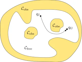
qI ∈ Cfree, the goal configuration of the robot qG ∈ Cfree, the free and obstacle configurations spacesCfree and Cobs, the motion planning problem requires to find a collision-free path τ such that τ(0) =qI and τ(1) =qG (see Figure 2.1).
Trajectory Let’s define a time parametrisation of a path as a strictly increasing function
Chapter 2. Background
Figure 2.1: The motion planning problem consists in finding a path connecting the start with the goal within theCfree space.
with s(0) = 0 and s(T) = 1, that gives the position on the path for each time instant t∈[0, T].
A trajectory Π is a path τ endowed with a time parametrisation s
Π : [0, T]→ C where Π(t) = τ(s(t)).
2.2 Motion Planning Algorithms
2.2. Motion Planning Algorithms
planning algorithms. A complete algorithm guarantees that it will be able to find a solution to the problem, if a feasible solution exists. Weaker notions of completeness are resolution completeness, i.e. the guarantee to find a feasible solution, when one exists, up to the resolution of the discretization, and probabilistic completeness, i.e. the guarantee that if a problem is feasible, a solution will be found with probability one when the running time tends to infinity.
In general, motion planning algorithms are classified into two main different families, distinguished by the way in which the configuration space is modelled:
• combinatorial: explicit representation of the configuration space.
• sampling based: implicit representation of the configuration space.
Combinatorial Motion Planning
Combinatorial Motion Planning algorithms are based on an explicit representation of the free configuration space Cfree. These kind of algorithms seeks to identify and model the topology ofCfree andCobs. Usually, the configuration space is represented as a graph, named “roadmap”, where nodes represent regions connected regions of Cfree, and edges model the connectivity between adjacent regions. The explicit representation of Cfree renders combinatorial motion planning algorithms complete, i.e. if a problem is feasible, in the end the algorithm will produce a valid solution. However, this kind of algorithms are computationally extremely expensive (due to the inherently high complexity of motion planning), and are therefore applicable only to small, low dimensional problems. Among this class of algorithms, common solutions inspired from computational geometry are the vertical cell decomposition approach, the visibility graph approach and the maximum clearance approach (based on the construction of a Voronoi diagram).
Chapter 2. Background
Sampling Based Motion Planning
Sampling Based Motion Planning algorithms, on the other hand, are based on an implicit representation of the configuration space. In general, sampling based algorithms incrementally explore the configuration space by sampling configurations within Cfree, and by connecting them to build graphs or trees of feasible paths. In general, since sampling based algorithms do not consider explicitly the configuration space, the task of determining whether a given configuration or path connecting two configurations is collision-free is delegated to a black-box collision detection module. For complex configuration spaces, the collision detection is in general one of the main bottlenecks for this family of algorithms. For this reason, usually extremely efficient data structures are adopted, and approximated, conservative approaches are applied to produce solutions with acceptable computational times.
Sampling based algorithms can be classified into two different families:
• Single-query: the algorithm needs to compute just a single path between a start configuration and a goal configuration. Therefore, this family of algorithms are mainly focused on exploring the regions of the configuration space that are of interest for a particular instance of the problem. Among single-query algorithms, popular solutions are based on the Rapidly-Exploring Random Tree (RRT) approach [19], that is probabilistically complete. An important extension of RRT, named RRT* [20], in addition to probabilistic completeness, guarantees also probabilistic optimality, meaning that, as the running time tends to infinity, the produced solution will converge to the optimum with probability one. To achieve this result, differently from the classical RRT algorithm, RRT* dynamically updates and “rewires” some subtrees of the current search tree, whenever shortest paths are found. • Multi-queries: the algorithm is required to solve many queries between
3
Related Work
In this chapter, we present state-of-the-art research related with the different kinds of planning problems that we are required to solve to produce the planning system for an assistive robot, and for the generation of time-optimal trajectories for autonomous racing cars. The various problems solved within the thesis are quite heterogeneous, and are therefore related with different research communities and different relevant literature. The remainder of this chapter, therefore, is organised in four different sections, covering the different families of problems tackled in the thesis. More in details, the first section is dedicated to the global motion planning, and focuses on existing algorithms to produce smooth and comfortable paths between pairs of given robot configurations. The second focuses on recently emerging trends in the field of “human-aware” motion planning, i.e. effective strategies to navigate a robot in environments populated by humans. The third section focuses on high-level reasoning techniques, dealing with the selection of an optimal subset of point of interest to visit on an abstract representation of the environment, given some specific constraints. Finally, the fourth section deals with the generation and dynamic adjustment of optimal time manoeuvres for racing vehicles.
3.1 Motion planning in static environments
Chapter 3. Related Work
should be short and smooth at the same time (i.e. avoid abrupt changes of direction and minimize lateral accelerations).
In literature, there are various solutions to generate smooth paths for nonholo-nomic, wheeled robotic vehicles but, in general, they are not focused on assistive robots, and are not modelling comfort indexes related to human users. These solutions can be roughly classified into two different categories.
On one hand, a large number of approaches are based on the decomposition of the problem into two distinct sub-problems, i.e. the generation of an initial “guess” solution ignoring the nonholonomic constraints, by using simple motion primitives (e.g. straight line segments) to connect the starting position with the goal, and on the successive refinement and smoothing of the path by means of more complex, smoother curves, such as Bezier splines, to achieve solutions with continuous tangent (G1-splines) or even curvature (G2-splines). The first problem, that is the generation of a simple path (i.e. a sequence of waypoints) connecting the starting position with the goal, can be solved using standard combinatorial based or sampling based motion planning algorithms (see Chapter 2). Regarding the second problem, i.e. the generation of a smooth path starting from a sequence of waypoints, common approaches are based on their interpolation or fitting using Bezier curves or polynomial splines [23,24], or on the simulation of a vehicle moving along the sequence of waypoints to obtain a smooth solution [25].
3.2. Socially acceptable navigation in human populated environments
While all of these solutions are capable of producing smooth G1 or even G2 continuous paths, that can be followed by a nonholonomic robot, they do not explicitly take into account the comfort perceived by a human user following the path that, as shown in Chapter 5, is related with the overall jerk. Moreover, solutions relying on the direct application of complex motion primitives, while being more robust and guaranteeing the feasibility of the generated path, often require elevated computational times, that are not applicable for our purposes. Indeed, for our motion planning system to be applicable on a robotic assistant for an elder user performing a social activity within a public space, the generation of a valid solution should take a few seconds at worst.
3.2 Socially acceptable navigation in human populated environ-ments
Chapter 3. Related Work
take explicitly into consideration the fact that these moving obstacles are actually humans, and therefore that it would be possible to apply existing human motion models to obtain more accurate predictions of their behaviours.
More directly related to our approach, based on an explicit consideration of human motion, are solutions that model the trajectory followed by pedestrians in a specific environment as Gaussian Processes [37], interactive Gaussian processes [38] or Hidden Markov Models [39]. The probabilistic information on the future position of the obstacles is used in different ways to find probabilistically safe trajectories. In this line of work, a large number of prior observations in a specific environment is used to fit the model parameters. For example, Risk-RRT [40] is based on the modelling of possible trajectories using a mixture of Gaussian Processes, and on the search of the solution using an adaptation of the RRT path planning algorithm [19]. The disadvantage of this kind of solutions is that they are applicable only to the specific scenarios for which the probabilistic model has been constructed (e.g. a corridor, a room, etc.). Whenever a different scenario has to be tackled, a new dataset of observations has to be constructed and used to produce a new, effective model. Our efforts are toward solutions that are more generally applicable and not bound to some specific scenario.
More accurate models describing human motion are considered in a different line of papers [41, 42]. The idea is in these cases to use Monte Carlo simulations to predict the future positions of the obstacles. This solution comes at the cost of a non-negligible computation time, which could potentially compromise the possibility of a real-time execution.
Besides, none of these solutions take into explicit consideration the smoothness of the path followed by the robot. Since in our context the synthesised path has to be followed not only by the robot, but also by the assisted human, an explicit consideration of the comfort perceived by the user is required while applying local adjustments to the global, reference path.
3.3. Activity Planning: linking high and low-level planning
aligned with their heading, due to the biomechanics of humans. This phenomenon has been observed by several studies [44, 45, 46], which come to the conclusion that a nonholonomic model, e.g. unicycle-like or car-like models, may be more appropriate to describe human motion. The adoption of such models gives a nice interpretation of the mechanism underlying the formation of human trajectories, i.e. the minimisation of the derivative of the path curvature, the jerk [45]. In [47] the Headed Social Force Model (HSFM) is proposed to enhance the traditional SFM by explicitly accounting for the pedestrians’ heading and thus retrieving the smoothness of the trajectories.
3.3 Activity Planning: linking high and low-level planning
The objective of the activity planner installed on the FriWalk is to determine, given the constraints, preferences and requirements of the user, a sequence of goals to visit, to maximize the value of the proposed activity. A strict interaction with the motion planner is fundamental for a correct characterisation of the properties and physical parameters associated with each action composing an activity.
Therefore, our activity planning problem bears important similarities with a family of optimisation problems known as Multi-Goal Path and Motion Planning. The objective of these problems is to determine the optimal path visiting a given set of goal locations. Existing solutions are based on the reduction of the problem to a Travelling Salesman Problem, solved exactly for small problems, or approximatively. For example, in [48], a Minimum Spanning Tree greedy approach is employed, and the edges of the tree are iteratively refined by lower-level motion planners until they become feasible. Other solutions presenting a strong synergy between high-level logical reasoning and low-level dynamic motion planning are applied in the literature for various applications, e.g. in [49] a multi-layered approach is adopted for the planning for ground and flying robots with consideration for the vehicles’ dynamics.
Another family of planning and optimisation problems related to the activity planner are the Partial Satisfaction Planning (PSP) [50], the Orienteering Problem (OP) [51], and in particular the Tourist Trip Design Problem (TTDP), whose
Chapter 3. Related Work
upper bound on the overall duration of the activity. Most state-of-the-art techniques to solve the Orienteering-Problem and its variants are based on the application of metaheuristic optimisation algorithms [52]. A rather complete survey on variants of the TTDP and possible solutions can be found in [53]. Unfortunately, to the best of our knowledge, there exist no solutions in literature capable of handling the kind of optimisation problems required by the activity planning system that we seek to develop, involving multiple probabilistic constraints. Indeed, the TSP is focused on the visit of all the nodes of the graph minimising the overall distance, whereas we are interested in maximising the total score achieved by visiting only a subset of the nodes that meet the user preferences, given deterministic and stochastic constraints. Most of the existing TTDP solutions handle exclusively deterministic constraints, others consider just a single stochastic bound. This represents a large limitation of these metaheuristic approaches, rendering them unsuitable to tackle the activity planning problem that we are required to solve, involving the effective handling of a number of probabilistic constraints.
Up to now, we have presented main research trends and relevant literature concerning the different problems that we have to face in order to develop a complete planning framework for assistive robotics. The remainder of this chapter, instead, deals with existing state-of-the-art research in the field of time-optimal trajectory planning for autonomous racing cars, that is the main focus of the second part of the thesis.
3.4 Time-optimal trajectory planning for racing cars
In his famous work Dubins [54] set the stage for the solution of path planning problems for vehicles moving at constant speed, with limited curvature radii and described by a kinematic model. More recently, Sanfelice et al. [55] applied the Pontryagin Maximum Principle to generalise Dubins results. Despite the recognised importance of these contributions, their applicability is limited in all cases in which dynamic effects, acceleration bounds and slipping constraints cannot be neglected (e.g., high speed vehicles or aggressive manoeuvres).
3.4. Time-optimal trajectory planning for racing cars
racing track. These techniques can be roughly classified into two different categories. On one hand, many solutions are based on the application of complex nonlinear optimisation tools and on the formalisation of the problem as an optimal control or as a geometric optimisation problem. On the other hand, we find solutions based on a direct, incremental exploration of the configuration space, inspired and adapted from the classical path planning algorithms presented in Chapter 2.
When modelling the minimum lap time problem as an optimal control (OCP), dynamic equations governing the motion of the system are translated into con-straints to satisfy. The solution of the obtained OCP can be based both on indirect or on direct methods. Indirect methods are based on the Pontryagin Maximum Principle [56], giving the necessary conditions for optimality, that are translated into a set of differential equations with boundary conditions. The resulting problem is therefore a two-points boundary value problem (TPBVP), associated with a cost functional to optimise, and can be solved using several numerical techniques. Solutions based on this approach can be found for example in [57,58,59, 60]. On the other hand, direct methods are based on the direct translation of the OCP into a discrete, constrained nonlinear programming problem (NLP), solved by standard numerical algorithms. Solutions based on a direct method are presented in [61, 62], while [63] reports a detailed comparison between the two methods. The major drawbacks of this kind of tools is the difficulty in the set-up, in the selection of the different parameters, and the lack of any convergence guarantee. In addition, this approaches lack the flexibility to easily model more complex scenarios, for example the presence of an obstacle along the way, that introduces a non-convex, binary choice in the optimisation problem, i.e. on whether to pass on the left or right side. Therefore, over the years, also different and alternative approaches have been developed, based on the fast generation and selection of feasible kinematic trajectories with a direct search over the configuration space, using and adapting classical path planning search algorithms, such as RRT or RRT* [64, 26, 20], and by incorporating information on the dynamic properties and constraints [65, 66, 67, 68,69]. The main weaknesses of these approaches are the elevated computational times required to yield a solution of high quality, and the necessity of sampling and efficiently determining nearest sets of configurations in non-metric and non-smooth spaces.
Chapter 3. Related Work
Part I
Introduction
The first part of the thesis focuses on the different kind of low and high-level planning problems that we are required to solve for the development of a complete planning system for an assistive robot. The following diagram illustrates the different interacting components that are part of the software infrastructure deployed on the robotic rollator to provide it with navigation assistance capabilities.
Activity Planner
Global Motion Planner
Reactive Replanner
Low-Level Navigation support
Robot Navigation
High-Level Activity Selection
Robot Control and Perception
Robot Controller
HMI Robot Perception
Knowledge Base User Profiles Enviroment Data
Low Level
known environment, and to navigate autonomously or in cooperation with the user. While this part of the research is outside the scope of this thesis, we will provide a brief description of the general principles and choices that have been made during the development of the assisitive robot. The localisation of the vehicle during the navigation is performed by means of a camera mounted in front of the vehicle, and a set of visual markers (QR codes) placed on the ground, whose absolute coordinates are known and used, together with odometry data obtained from optical encoders mounted on the wheels, to yield highly accurate self-positioning information. Regarding the actual robot navigation, different guidance solutions have been developed, with main focus on the effective sharing of authority between the assistive walker and the elder, that, depending on his cognitive capabilities, can be given more or less authority and freedom during the execution of the navigation task.
At the intermediate level of the software infrastructure we find the low-level planning components, i.e. the motion planning and the reactive planning modules. The motion planning takes as input the known map of the environment, the initial position of the robot and the desired goal destination, and generates a collision free, safe path specifically tailored to be comfortably followed by an human. The aim of the reactive planner, on the other hand, is to locally and dynamically adjust the global path generated by the motion planner on real-time during the navigation, to cope with unforeseen external factors that render the execution of the original plan infeasible. The state of the surrounding environment is provided by the low-level sensing system, and contains information on the position of static obstacles and position and velocity of approaching pedestrians. Through this information, the algorithm is able to monitor the risk of collision with the surrounding obstacles while moving along the reference path. Whenever the probability of an accident exceeds a certain threshold value, a local replanning is applied, to adjust the reference trajectory and render it safe again.
Common building blocks
problem at hand. Geometric
Module
- Geometric interpolation - Spline manipulation
Collision Detection Module
- Model of the environment - Efficient test for collision of splines/paths
Optimisation Module
- Efficient cost computation for splines/paths
Firstly, we need an effective way to generate, manipulate and adjust (portions of) a geometric path to be followed by the robot. Secondly, once a geometric path has been computed, the planning algorithm needs to check whether the path is feasible, i.e. whether there are no collisions with any of the known obstacles. Thirdly, to produce an “optimal” solution, once a path has been synthesised, we need some efficient way to evaluate its quality/cost, depending on the properties of the path that are of interest for the specific problem under consideration.
High Level
At the top level of the depicted software architecture lies the activity planner. It works on an abstraction of the environment, that is represented as a graph, with nodes corresponding to known attractions and points of interest, and edges corresponding to connections between this locations. Therefore, each edge maps to a specific navigation action between a pair of points of interest, and is thus associated with some random variables modelling in probability physical properties associated with that specific action (e.g. travel length, travel time, ...), that are characterized by means of a large number of simulations run on the map of the environment (and adjustable with real data collected during the execution of these actions).
4
Clothoid Curves
This chapter is devoted to review the definition and properties of clothoid curves, that are the basic motion primitives adopted for all the developed global and local motion planning algorithms. Based on the recent developments and new state-of-the-art algorithms to efficiently solve different kind of problems involving the interpolation of clothoids with different constraints, appropriate strategies and solutions have been applied to integrate and apply these curves to solve different kinds of motion planning problems.
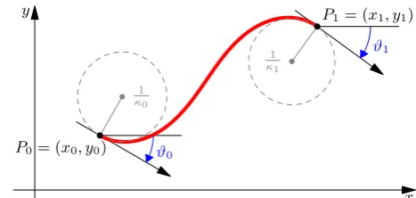
A clothoid, known also under the names of Euler spiral and Cornu spiral, is a curve in the plane with the property that the curvature varies linearly with respect to the arc length.
A clothoid arc can be represented as a parametric function of the arc-length s
via the Fresnel Integrals [76], and is characterised by six real parameters: (x0, y0), the initial point, θ0, the initial angle, κ, κ0 the curvatures and the length L. The space coordinates of a point on the clothoid at arc-length s, the corresponding angle and curvature are given by:
x(s) = x0+ Z s
0 cos
1 2κ
0t2+κt+θ 0
dt (4.1)
y(s) = y0+ Z s
0 sin
1 2κ
0t2+κt+θ 0
dt (4.2)
θ(s) = 1 2κ
0s2+κs+θ
0, (4.3)
4.1. Computational Issues
y
x P0= (x0, y0)
P1= (x1, y1)
1 κ0 1 κ1 ϑ0 ϑ1
Figure 4.1: An example of a clothoid arc and its parameters.
By using the Fresnel Generalised Integrals, defined as:
Xj(a, b, c) = Z 1
0
τjcosa 2τ
2+bτ +c dτ,
Yj(a, b, c) = Z 1
0
τjsina 2τ
2+bτ +c dτ,
and given the following identities, obtained by a simple change of variables: Z s
0
τjcosa 2τ
2+bτ +cdτ = s1+jX
j(as2, bs, c), Z s
0
τjsina 2τ
2+bτ +cdτ = s1+jY
j(as2, bs, c), equations (4.1) and (4.2) can be rewritten as:
x(s) = x0+s X0(s2κ0, sκ, θi) y(s) = x0+s Y0(s2κ0, sκ, θi).
In Figure 4.1 is shown an example of a clothoid arc and its parameters.
4.1 Computational Issues
Chapter 4. Clothoid Curves
remainder of this section is devoted to the presentation of some of these problems involving clothoid curves that are relevant for motion planning applications, and that are used in different ways to solve the various planning problems presented in the next chapters of this thesis. An open source library implementing all the algorithms and efficient solutions discussed in this chapter is available online, at [77]. 4.1.1 G1 and G2 Hermite interpolation problems
G1
Hermite interpolation problem The G1 Hermite Interpolation Problem requires to find the clothoid arc interpolating a given initial position (x0, y0) and orientationθ0 with a given final position (x1, y1) and orientation θ1. More formally, we need to solve the following system:
x0(s) = cosθ(s), x(0) = x0, x(L) = x1, y0(s) = sinθ(s), y(0) = y0, y(L) = y1, θ0(s) = k(s), θ(0) = θ0, θ(L) = θ1,
whereL >0 is the total length of the curve. An efficient, numerically robust solution to this problem is discussed in [76]. The paper shows how this problem can be solved with a single clothoid curve. The problem is thus to find the three unknown parametersκ,κ0andLof this curve, and is solved by reducing the original nonlinear system of three equations and three unknowns to a single nonlinear equation. A root of this nonlinear equation is found using the Newton-Rhapson technique; with the good initial guess proposed in the paper, convergence is achieved in at most four iterations (with a tolerance of 10−10). The found solutions can finally be used to compute the three unknown parameters.
G2
4.1. Computational Issues
and curvature κ1. More formally, we need to solve the following system: x0(s) = cosθ(s), x(0) = x0, x(L) = x1,
y0(s) = sinθ(s), y(0) = y0, y(L) = y1, θ0(s) = k(s), θ(0) = θ0, θ(L) = θ1, k0(s) = u(s), k(0) = κ0, k(L) = κ1,
whereL >0 is the total length of the curve andu(s) is a piecewise constant function to be determined that can be interpreted as a control variable, representing the
κ0 parameter associated with each clothoid curve composing the solution. Indeed, differently from the G1 interpolation problem, the G2 cannot generally be solved with a single arc, but instead requires up to three arcs. In [78] a numerically robust and efficient solution to this problem is proposed. The original nonlinear system is composed by eight equations and ten unknowns, but for the computation of a solution it is reduced to a system of two equations with four unknowns, solved with just a few iterations of Newton-Rhapson. The system is underconstrained, but the feasibility of the problem is strictly dependent on the correct choice of the two free parameters. Thus, a relevant part of the paper is dedicated to the analysis of the correct selection of the values for these parameters.
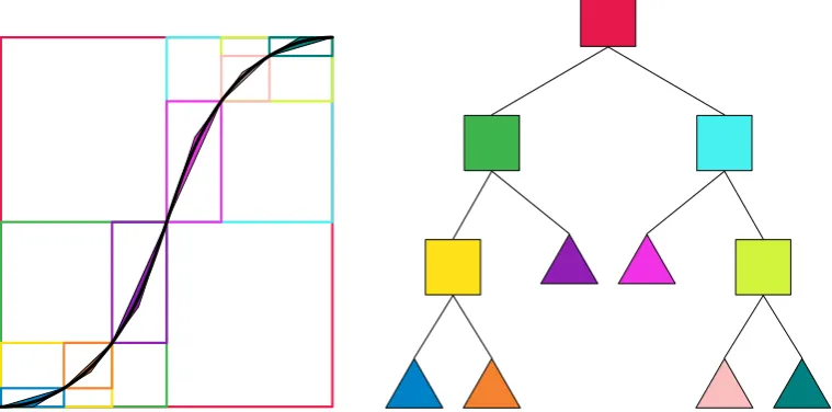
4.1.2 Intersection of clothoid arcs
Chapter 4. Clothoid Curves
of triangles. The original problem is thus simplified to an intersection between triangles: if a triangle of the first curve overlaps a triangle of the second curve, then the Newton method is applied only on the corresponding subarcs. Often we are required to test for intersection pairs of clothoid splines, i.e. sequences of clothoid arcs joining withG1 or G2 continuity. In these circumstances, the number of subarcs resulting from the decomposition may be quite large, so, to speed up the computation, it is convenient to organise the resulting set of triangles into a hierarchical spatial partitioning data structure.
Triangle construction
To inscribe a clothoid arc into a triangle, first it must be split into subarcs with constant curvature sign, so that each of them is convex or concave. Notice that, each clothoid arc can have at most one change of sign in the curvature, fors =−κ/κ0. If s ∈[0, L], i.e. the inflection point lies within the arc, a split is applied at this point to obtain two clothoid subarcs.
Each of the clothoid subsegments satisfying the constraint on the curvature sign has to be furtherly split into subarcs such that the travelled angle is less than a chosen parameterαmax. To enclose a clothoid subarc inside a triangle, αmax has to be smaller than π. However, in practice, to improve the quality of the solution, and determine a set of triangles with a good fitting of the original curve, much lower values of αmax are chosen (e.g., we usually adopt the values π/8 or π/16).
Given each clothoid subsegment originating from (x0, y0) with initial orientation θ0 and terminating in (x1, y1) with final orientation θ1, the circumscribing triangle is constructed by selecting the two endpoints of the arc as two vertices, i.e. P0 , (x0, y0), P1 , (x1, y1). The third vertex P2 ,(x2, y2) of the triangleP0P1P2 is determined as the intersection of the tangent lines in P0 and inP1. The tangent at P0 isy =m0x+q0, wherem0 = tan(θ0) and q0 = y0−m0x0. In the same way, the tangent atP1 isy= m1x+q1, wherem1 = tan(θ1) andq1 = y1−m1x1. Henceforth, the point P2 has coordinates:
P2 =
− q0−q1 m0−m1
, m0q1−m1q0 m0−m1
4.1. Computational Issues
Efficient spatial partitioning: AABB trees
In the previous section we illustrated how it is possible to cover a clothoid arc with a set of triangles. However, for large clothoid splines, the number of triangles grows quickly. The determination of all the intersections between two splines requires a test for overlap between all pairs of triangles of the two splines. The computational time is thus quadratic in the number of triangles (i.e. in the size of the splines), and becomes prohibitive for various real-time applications. For this reason, it convenient to organise the sets of triangles into efficient data structures. In particular, we use Bounding Volume Hierarchies, with Axis Aligned Bounding Boxes (AABB) as Bounding Volume Primitives, [79]. Bounding volume primitives are simple volumes encapsulating more complex objects. The idea is that, by using simple bounding shapes, the test for intersection is computationally cheap, and a first, broad-phase, collision detection test can be performed, to filter out and reduce the number of more complex, accurate and costly intersections.
The construction is done by determining the minimum and maximum coordin-ates of the triangle P0P1Pm. The intersection can be determined with at most 4 comparisons, by checking whether one of the two AABBs lies completely on one side of the other. Let p1 and p2 be two AABB bounding primitives, where p1 lies between (xmin1 , y1min) and (xmax1 , y1max), and analogously for p2. There is no overlapping if
xmax1 < xmin2
∨ xmax2 < xmin1
∨ ymax1 < y2min
∨ y2max< ymin1
.
Chapter 4. Clothoid Curves
of these two subsets to generate two subtrees, corresponding to the two children of the current root node. The recursion terminates when the current set of boxes is empty or contains a single element, that corresponds to a leaf node, associated with a single triangle. The pseudo-code is shown in Algorithm 1. Given two AABB trees associated with two clothoid splines, the determination of the pairs of intersecting triangles can be performed by a recursive traversal of the two trees. First the bounding boxes associated with the root nodes are tested for intersection. If the test fails, the two curves are not intersecting, and the algorithm terminates. Otherwise, the test for intersection is repeated recursively on all the pairs of children nodes of the two trees. If the test for intersection succeeds, the traversal of the trees continues until pairs of leaf nodes are reached. At this point, the more accurate (but more expensive) triangle-triangle intersection test is performed [80]. For all pairs of intersecting triangles, the actual clothoid-clothoid intersection test is performed on the corresponding clothoid segments. The pseudo-code is shown in Algorithm 1. The complexity of building an AABB tree isO(nlogn) on average andO(n2) in the worst case [81], whereas the complexity of a collision detection or an intersection test is on average O(mlogn), where n, m are the number of primitives of the two trees. In the worst case, the cost increases to O(nm). Without this algorithm the complexity of an intersection test would be always O(nm), because each primitive of the first tree must be compared with all the primitives of the second tree.
In Table 4.1 are reported the computational times required for finding the intersection of two clothoid splines (with n and m triangles, respectively) with and without the adoption of the hierarchical partitioning strategy. The results are obtained on a 2.9GHz Intel Core i7 with 16Gb ram. It is clear how the hierarchical approach is much more efficient, especially for large problems involving many triangles.
Size (n, m) (54,53) (265,344) (340,333) AABB tree 0.2 ms 2 ms 2 ms plain 3.5 ms 170 ms 132 ms
4.1. Computational Issues
Chapter 4. Clothoid Curves
Algorithm 1: AABB tree construction and intersection
1 BuildTree(Boxes); 2 begin
3 if Boxes=∅then returnnil;
4 if #Boxes= 1 then return(Boxes1, nil, nil);
5 root←Bbox(Boxes);/* finds global Bbox */ 6 w←Width(root);h←Height(root) ;
7 if w > hthen
8 split←meanx(Boxes);/* splits vertically */
9 B1← {b∈Boxes s.t. centroidx(b)< split}; 10 B2← {b∈Boxes s.t. centroidx(b)≥split}; 11 return(root,BuildTree(B1),BuildTree(B2));
12 else
/* same as above but horizontally */
13 end
14 end
15 Intersect(T1,T2 );
16 begin
17 if (T1=nil)or(T2=nil)then return ∅;
18 if isLeaf(T1) and isLeaf(T2)then
19 if TriInt(getT(T1)),getT (T2)) then return(getT(T1),getT(T2));
20 return∅;
21 end
22 res← ∅;/* N.B: Children(leaf) returns leaf itself */ 23 foreachc1∈Children(T1)do
24 foreachc2∈Children(T2)do res←res∪Intersect(c1, c2) ;
25 end
5
Motion Planning
5.1 General Overview
In this chapter, we introduce the problem of motion planning for assistive robotics. The development of a motion planner tailored for robots employed to support and assist elder humans during the navigation of complex environments is a challenging task, that requires the consideration of different aspects. Like in the case of a classical motion planning problem, the generated path has to connect the initial and the final configurations, to lie entirely in the free configuration space and to be feasible, given the physical constraints of the robot. In addition, this specific kind of motion planning problems require an explicit and careful consideration of the geometry and smoothness of the produced path, that has to be followed by human users with the support of the robotic assistant. Therefore, additional constraints and a more complex objective function need to be considered, in order to maximize their perceived comfort.
Specifically, a number of studies has been conducted over the years to analyse the (lack of) comfort of humans moving on ground vehicles, such as cars or trains. It has been recognised how the discomfort increases with body accelerations and jerk. These terms, in the context of a mobile robot following a given reference trajectory, are in turn related with the curvature of the path and its discontinuities. Therefore, for the generation of a path optimizing the user comfort, both its length and jerk should be minimized.
Chapter 5. Motion Planning
generate a solution. Indeed, in order to render the system trustable and compelling from the point of view of the user, the generation of a plan should take no longer than a few seconds.
To develop an efficient solution to this challenging task, it is convenient to isolate two different sub-problems: 1) generation of a collision free sequence of waypoints to reach the destination, and 2) synthesis of a path joining the waypoints, respecting the physical constraints, and minimizing the cost function associated with the problem. These two sub-problems can be solved separately during different phases of execution of an iterative algorithm, discussed in the next sections.
5.2 Problem Statement
This section is devoted to present the model of the robot, the cost function combining a set of discomfort indices to be minimised, and from these a formalization of the motion planning problem at hand.
5.2.1 Platform Model
The large majority of assistive robots can be modelled from a control perspective as unicycle–like or car–like vehicles. With reference to Figure 5.1, let hWi =
{Ow, Xw, Yw, Zw} be a fixed right-handed reference frame, whose plane Π = Xw×Yw is the plane of motion of the vehicle, Zw pointing outwards the plane Π and let Ow be the origin of the reference frame. Let x= [x, y, θ]T ∈R2×S be the
kinematic configuration of the platform, where (x, y) are the coordinates of the mid–point of the rear wheels axle in Π and θ is the orientation of the vehicle w.r.t. the Xw axis (see Figure 5.1). Assume that the kinematic model of the mechanical platform can be assimilated to a unicycle–like vehicle, described by
˙ x ˙ y ˙ θ =
vcos(θ)
vsin(θ)
ω
(5.1)
where v and ω are the forward and the angular velocities.
5.2. Problem Statement
x(s)
y(s)
k(s) = +0s
✓(s)
Zw Xw Yw ✓0 ✓1 P1 P0
Figure 5.1: The reference system for the trajectory planning with clothoidal elements. [Published in [11]]
experienced by the user. This, in turn, translates to a minimization of the acceler-ations and jerk, determined by the geometry of the generated path, that should be continuous at least up to the curvature [82]. Since the unicycle model in (5.1) does not satisfy this requirement, we propose a dynamic extension of the unicycle model, whose kinematic ODEs in the cartesian xy-coordinates are given by:
˙ x ˙ y ˙ θ ˙¯ δ =
cos(θ) sin(θ)
¯ δ 0 v+ 0 0 0 1 ¯ ω, (5.2)
where ¯δ can be interpreted as the steering angle and ¯ω its velocity.
Chapter 5. Motion Planning
with rear traction, described by ˙ x ˙ y ˙ θ ˙ δ =
cos(θ) sin(θ) tan(δ)/l
0 v+ 0 0 0 1
ωδ, (5.3)
where δ is the actual steering angle, ωδ is the normalised angular velocity of the steering wheel and l >0 is the wheelbase. In this case, the kinematic model (5.3) can be easily reduced to the model (5.2) by using the auxiliary control input
¯
ω= δ2+ 1ωδ, and assuming that tan(δ)≈δ¯(see [83,84]).
In [45], a large number of real trajectories followed by groups of people moving in a real environment is analysed. The results show how these trajectories are well approximated by the optimal solution of model (5.2).
5.2.2 Comfort
During the last years, a relevant amount of research has been dedicated to an accurate modelling and a deep understanding of the trajectories followed by walk-ing humans. An important research direction regards the determination of the functional that a person optimises while walking, and of a suitable dynamic system to describe it. While convincing results on the latter problem are available in the form of a system of differential equations that governs the human locomotion, the optimised functional is much more difficult to understand and model accurately. One possible formulation, based on model (5.2), has been developed in [45], where it is shown that an human tends to move with a constant longitudinal velocity along its reference trajectory. In addition, this trajectory is determined by optim-ising a functional representing the minimum square of the jerk, that is defined as the derivative of the acceleration. An extended experimental validation has shown the effectiveness of the proposed human model, matching the ground truth measurements taken from real pedestrians very satisfactorily.
5.2. Problem Statement
j =v2k˙. For the optimal curve resulting from the human motion model, i.e., the clothoid, the curvature is a linear function of the arc-length s (see chapter 4). Thus we specialise the expression of the jerk combining the information of the curvature, which yieldsj = v2κ0. By assuming the velocity to be constant, according to [45], we can consider as a measure of the trajectory jerk the square ofκ0. As a consequence, a possible cost index that can be considered for the human comfort is the minimisation of the jerk, i.e.
T1 =f1(κ02),
where f1(·) is a suitable function to be defined. While the jerk is obviously relevant, other comfort indices could be considered as well. From the previous analysis, a minimisation of the overall curvature can also be a suitable cost index to be minimised to increase the comfort, which can be denoted as:
T2 =f2(κ, κ0).
Finally, according to [82], the minimisation of the path length could be considered as a relevant comfort index, i.e.
T3 =f3(κ, κ0),
where T3 is equal to the time optimal path, the velocity v being assumed constant.
5.2.3 Problem Formulation
This subsection is dedicated to the formal definition of the motion planning problem that we are required to solve.
First of all, the cost index to optimize contemplates different aspects: • the overall length of the path
• the time required to walk to the destination • the comfort along the path
Chapter 5. Motion Planning
the smoothness and perceived comfort. Mathematically, the objective of this optimization problem can be stated as the weighted sum of the three terms:
minJ =w1 Z
γ
ds+w2 Z
γ
dt+w3 Z
γ
c(s) ds (5.4)
where the first term represents the overall path length, the second the travel time and the third the discomfort index.
The problem that we are solving, is thus to determine a collision-free path connecting two given positions with a spline of clothoid curves, optimizing the cost function (5.4).
5.3 Proposed Solution
As mentioned in the introduction of this chapter, given the particular kind of application, a fundamental aspect that we need to consider is the computational time required to determine a solution, that should be limited to at most a few seconds. For this reason, our solution is based on the identification and separate solution of two different sub-problems:
• Generation of a reference route, modelled as a spline of line segments, determ-ining a collision-free “corridor“ within the known map of the environment • Selection of a sequence of waypoints along the reference route, and
interpola-tion with a spline of clothoids characterised by G2 continuity and minimizing the target functional
5.3.1 Route planning
5.3. Proposed Solution
the whole approach applicable within the context of assistive robotics, that, as previously mentioned, requires the computation of a solution in a limited amount of time.
In particular, we have applied a well-known sampling based motion planning algorithm, that is a variant of the RRT*, called Informed-RRT* (I-RRT*) [85]. Initially, while a feasible solution has not been found, this algorithm behaves identically to RRT*. A new point xnew is sampled within the free configuration space during each iteration of the algorithm, and is connected to its closest node
xnearest among the subset of nodes of the tree that are directly reachable from xnew (i.e., the subpath associated with the new edge of the tree must lie in the free configuration space). When a node is inserted, the path and the cost to reach neighbour nodes already in the tree by passing through this new node are computed. For all the neighbours for which this new path is collision free, and its cost is lower than the current cost, a “rewiring” operation is performed, i.e., the new node is set as their parent, and the costs of the associated subtrees are updated accordingly. Differently from traditional RRT*, when a solution has been found I-RRT* does not sample all the possible regions of the free space anymore, but it samples possible candidates only within an elliptical region of the configuration space for which an heuristically calculated total-cost is lower than the current optimal cost.
The pseudocode illustrating the main steps of this algorithm is shown in Algorithm 2. In Figure 5.2, on the top-left is shown (in blue) the tree constructed after a few iterations of the I-RRT* algorithm.
5.3.2 Path generation
Chapter 5. Motion Planning
Algorithm 2:Generation of a route (spline of segments) from a given starting position to a given goal, using I-RRT*.
Data: map,start,goal
Result: Route from start to goal
1 function GenerateRoute
2 tree← initT ree(start, goal) 3 ellipse← initEllipse(start, goal)
4 termConditions← initT ermConditions()
5 while (not termConditions)do
6 sampleP os← sampleN extP osEllipse(map, ellipse)
7 parentF ound← f indP arent(sampleP os, map, tree, parent, minCost)
8 if parentF oundthen
9 newN ode← insertN ewN ode(sampleP os, tree, parent, minCost)
10 rewireN eighbours(newN ode, map, tree)
11 if goalInRange(sampleP os, goal, map) then
12 connectGoal(node, goalN ode, tree)
13 end
14 updateEllipse(ellipse)
15 end
16 termConditions← updateT ermConditions(termConditions)
17 end
18 route← extractRoute(tree)
19 return route
20 end
aligned intermediate points (line 2). Then, a certain number of waypoints is inserted near to the location where there is a change of direction in the segment spline, to force the interpolated path to stay close to the reference route (line 13). The distance between consecutive waypoints is a parameter of the algorithm. If the clothoid connecting two waypoints was in collision during the previous iteration, the distance between consecutive waypoints is reduced, depending on the current number of attempts (line 11). Finally, the sequence of waypoints is interpolated. If the resulting clothoid spline is not colliding with any obstacle, the algorithm terminates, otherwise, the indexes of the colliding segments are stored and used to perform a new iteration of the algorithm.
5.3. Proposed Solution
spline.
Algorithm 3: Generate a collision-free spline of clothoids interpolating a segment spline
Data: map: map of environment, points: spline of line segments
Result: Smooth path interpolating the given waypoints
1 function GeneratePath
2 points ←Filter(points)
3 collisionSegments←∅
4 for i∈1. . . attempts do
5 waypoints←∅
6 for j∈2. . .Length(points) do
7 p1 ←points[j−1]
8 p2 ←points[j]
9 step ←STEP SIZE
10 if (j−1)∈collisionSegmentsthen
11 step ←(2/3)i−1STEP SIZE COLLISION
12 end
13 waypoints←waypoints ∪ GenIntermPts(p1, p2, stepLen)
14 end
15 spline ←InterpolateSpline(waypoints)
16 collisionSegments←Collision(spline, map)
17 if Empty(collisionSegments) then
18 return spline
19 end
20 points ←waypoints
21 end
22 return ∅
23 end
G2
Spline Interpolation
Chapter 5. Motion Planning
![Figure 1.2: Example of the FriWalk robotic walker developed within the ACANTOproject [9]](https://thumb-us.123doks.com/thumbv2/123dok_us/458917.2044221/16.595.173.423.99.355/figure-example-friwalk-robotic-walker-developed-acantoproject.webp)
![Figure 1.3: The Roborace autonomous racing car: Robocar [10]](https://thumb-us.123doks.com/thumbv2/123dok_us/458917.2044221/18.595.111.486.232.483/figure-roborace-autonomous-racing-car-robocar.webp)
![Figure 5.1: The reference system for the trajectory planning with clothoidalelements. [Published in [11]]](https://thumb-us.123doks.com/thumbv2/123dok_us/458917.2044221/51.595.137.467.96.357/figure-reference-trajectory-planning-clothoidalelements-published.webp)
![Figure 5.2: [Top-left] The tree constructed after a few iterations of I-RRT* (inblue), and the optimal route found so far (dotted red)](https://thumb-us.123doks.com/thumbv2/123dok_us/458917.2044221/63.595.99.497.108.612/figure-left-constructed-iterations-inblue-optimal-route-dotted.webp)