Published online December 31, 2014 (http://www.sciencepublishinggroup.com/j/ijrse) doi: 10.11648/j.ijrse.s.2015040101.18
R-290 vapor compression heat pump for recovering and
upgrading waste heat of air-conditioner by using spiral coil
tank
Nattaporn Chaiyat
*, Natthawud Dussadee
School of Renewable Energy, Maejo University, Chiang Mai, Thailand
Email address:
benz178tii@hotmail.com (Chaiyat N.), natthawu@yahoo.com (Dussadee N.)
To cite this article:
Nattaporn Chaiyat, Natthawud Dussadee. R-290 Vapor Compression Heat Pump for Recovering and Upgrading Waste Heat of Air-Conditioner by Using Spiral Coil Tank. International Journal of Sustainable and Green Energy. Special Issue: Renewable Energy Applications in the Agricultural Field and Natural Resource Technology. Vol. 4, No. 1-1, 2015, pp. 50-56. doi: 10.11648/j.ijrse.s.2015040101.18
Abstract:
In this study, a concept of using a vapor compression heat pump for recovering and upgrading waste heat of an air-conditioner has been presented. R-290 has been selected due to its high efficiency and the environmental impact. R-290 heat pump at heating capacity 3 kW has been constructed to recover waste heat from the discharge refrigerant leaving compressor of R-134a air-conditioner at cooling capacity 1 TR. From the study results, it could be seen that the modified unit gives better EERAC when the cooling water does not over 43ºC. A set of simplified model has been developed to predict the systemperformance and the simulated results agree quite well with the measured data. Moreover, profile of hot water consumption in the department of children's hospital room, Maharaj Nakorn Chiang Mai Hospital is chosen to study. It was found that the hospital requires hot water is 0.815 m3/d at 50 ºC temperature, one unit of R-290 heat pump is enough to generate hot water with the economic results of saving cost and payback period around 765.46 USD/y and 1.97 y, respectively.
Keywords:
Air-Conditioner, Vapor Compression Heat Pump, Performance Curve, Heat Recovery, Spiral Coil Tank1. Introduction
Vapor compression heat pump (VCHP) is one technology for upgrading a low temperature heat to a higher temperature level. In a conventional VCHP, the low temperature heat is supplied at the evaporator and delivered the higher temperature at the condenser. Theoretical and experimental studies of the VCHP have been reported by various literatures. Chaiyat and Chaichana [1] simulated the natural working fluid used in vapor compression heat pump for generating hot water at 70 ºC. The heat source was hot spring at the temperature around 40-50 ºC. Five working fluids, R-290 (Propane) R-600 (Butane) R-600a (Isobutane) R-1270 (Propylene) and R-717 (Ammonia) were selected. The considered parameters were the unit heat transfer, mass flow rate, specific volume, maximum pressure, maximum temperature and COP of the cycle. It was found that the suitable natural working fluid was R-290 for the geothermal heat pump. Chaiyat and Kiatsiriroat [2] presented the experimental study of R-123 vapor compression heat pump to recover waste heat from water-cooled condensers. Waste heat was upgraded and generated hot water up to 70 ºC. The
EER of the water-cooled air-conditioner increased around 20% higher than that of the air-cooled unit.
Heat pump has also been used to recover heat from extracted vapor of the agricultural product during drying and heat could be upgraded to a higher temperature and supplied to generate hot air. The heat pump drying was found to be an effective equipment for drying high quality produce with low energy consumption as reported by Singharajwarapan and Chaiyat [3], Pendyala et al. [4], Chou et al. [5], Clements et al. [6], Young et al. [7] and Sadchang [8].
energy or geothermal energy. The low quality heat could be developed to a higher temperature at the condenser and used in other processes. In this study, the heat pump is used to recover waste heat of the refrigerant leaving compressor by the spiral coil water tank at the series connection with the air-cooled air-conditioner to generate hot water.
The objective of this research is to study the possibility for using the vapor compression heat pump which is used to recover waste heat from the air-conditioner and upgraded heat to generate hot water compared with the electrical water heater in the department of children's hospital room, Maharaj Nakorn Chiang Mai.
2. System Description
Generally, heat transfers from the high temperature heat source to the low temperature heat sink. For process to reverse heat, heat pump is needed and a power consumption from the external source is used to transfer heat from the low temperature heat source to the high temperature heat sink as shown in Fig. 1.
L
Q
H
Q
Input
W
Figure 1. The heat pump concept.
E Q C Q
Comp W
Figure 2. Vapor compression heat pump cycle.
The main components of vapor compression are compressor, condenser, evaporator and expansion valve as shown in Fig. 2. The working fluid has a low boiling temperature at a low pressure (PL). At state 1, the fluid in
vapor phase is boiled at the evaporator and compressed in the compressor to state 2 to a high pressure (PH). The vapor at the
high temperature and pressure is condensed in the condenser to be liquid at state 3. The liquid is then throttled to low
pressure at the expansion valve at state 4. Temperature of fluid will drop down, thus, the fluid could be absorbed low temperature heat at the evaporator again and the new cycle restarts.
The basic equations for the behavior of each component in the VCHP cycle as presented in Fig. 2 are as follows:
Evaporator
E re f 1 4
Q = mɺ ( h −h ) (1)
re f 1 2 3 4
m
ɺ
=
m
ɺ
=
m
ɺ
=
m
ɺ
=
m
ɺ
(2)E da a ,i a ,o W W
Q =m (hɺ −h ) M h− (3)
Compressor
C o m p re f 2 1
W
=
m
ɺ
( h
−
h )
(4)1 2
s = s (Isentropic process) (5)
'
Comp (h2 h ) / (h1 2 h )1
η = − − (6)
Condenser
C ref 2 3
Q =mɺ (h −h ) (7)
C HW bulk,HW HW,o HW,i
Q =mɺ Cp (T −T ) (8)
Expansion valve
3 4
h
=
h
(Throttling process) (9)Energy efficiency ratio (EER) for heating
Heating C Sys
EER =Q / W (10)
Energy efficiency ratio (EER) for cooling
Cooling E Sys
EER =Q / W (11)
3. Material and Method
In this study, the vapor compression heat pump is used for recovering rejected heat from the air-conditioner which is modified to add a spiral coil water tank in the air-conditioner cycle. The diagram to improve the air-conditioner by using the heat pump and the spiral coil tank are given in Fig. 3.
The cool water tank with having the spiral coil absorbs heat from a superheat refrigerant leaving the compressor at high temperature around 60-80 ºC. After that, refrigerant at lower temperature is sent to the air-cooled condenser which means a low condensing temperature (TC) and a low power
is a high efficiency in term of heat of vaporization and a friendly environment in terms of atmospheric life time, ozone depletion potential and global warming potential. The component descriptions of the air-conditioner and the heat pump are given in Table 2 and Table 3, respectively.
Table 1. Properties of various refrigerants [10-12].
Refrigerant R-22 R-290 R-134a
Critical temperature (oC) 96.14 96.68 101.06
Critical pressure (MPa) 4.99 4.25 4.06 Critical density (kg/m3) 523.84 218.50 511.90 Boiling point (oC) -40.81 -42.09 -26.07
Heat of vaporization (kJ/kg) 164.24 302.30 160.88 Flammability NO YES NO
Toxicity NO NO NO
Atmospheric life time (y) 13.3 < 1 14 ODP1 (CO2-ralated) 0.034 ~ 0 0.0015
GWP2 (100 y) 1780 0 1320
Note: 1 Ozone depletion potential 2 Global warming potential
The air-conditioner in testing room is tested its thermal performance firstly with the air-cooled condenser and then the result is compared with the unit with spiral coil tank and heat pump. For the latter case, the heat pump recovered heat from the cooling water in the spiral coil tank and upgraded to generate hot water in the hot water tank. The experiments in each case are tested as shown the details of the testing procedures in Fig. 3.
) C (
) C (
Figure 3. R-290 Vapor compression heat pump for recovering and upgrading waste heat from the air-conditioner.
Table 2. Descriptions of the air-conditioner components.
Devices Properties
Fan coil Fin and tube heat exchanger Capacity 3.516kW (1 TR) Tube size (OD) 5.0 mm Fins per inch 18 FPI
No. of rows & column 2R, 15C Compressor Hermetic (rotary) compressor R-134a
Devices Properties
Capacity 1.434kW Compression ratio 6.0 Max Condenser Fin and tube heat exchanger
Capacity 5.275kW Tube size (OD) 7.0 mm Fins per inch 18 FPI
No. of rows & column 2R, 36C Expansion
valve
Capacity 3.516 kW Pressure ratio 3.00 Orifice typethermo static
Table 3. Descriptions of the heat pump components.
Devices Properties
Compressor Reciprocating compressor R-22 Power input 1.3 kW
Evaporator Plate heat exchanger Capacity 4.00 kW Area 0.65 m2
Condenser Plate heat exchanger Capacity 5.00 kW Area 0.88 m2
Expansion valve
Thermo static orifice 02 Capacity 5.00 kW Pressure ratio 3.00 Spiral coil tank Capacity 150 L
4. Results and Discussion
4.1. Performance Curve of the Air-Conditioner
For this study, a performance curve of vapor compression cycle is developed which is a mathematical correlation between of an energy efficiency ratio (EER) and a different temperature of air entering at condenser and evaporator (Ta,C,i
– Ta,E,i).
Fig. 4 shows a cooling energy efficiency ratio for cooling (EERAC) of the tested air-conditioner before improvement
with the temperature difference between the air entering at condenser and evaporator (Ta,C,i – Ta,E,i). It could be seen that
the EERAC decreases when the temperature difference
increases which follows the Carnot efficiency concept.
y = -0.162x + 5.2896 R² = 0.9313
y = -0.0889x + 4.3414 R² = 0.8298
0.0 1.0 2.0 3.0 4.0 5.0 6.0
0.0 2.0 4.0 6.0 8.0 10.0 12.0
E
E
RA
C
Ta,C,i -Ta,E,i(oC)
Figure 4. Performance curve of the normal air-conditioner and the modified air-conditioner by using the spiral coil tank and the heat pump unit.
normal air-conditioner which means that the modified unit consumes the lower electrical power compared with that of the normal unit at the same cooling capacity as shown in Fig. 4. However, for using the spiral coil tank, when the rejected heat is recovered and accumulated as hot water, at the value of Ta,C,i
– Ta,E,i around 12 ºC or water temperature in the spiral coil
tank is around 43 ºC, the EERAC tends to be lower than that of
the normal air-cooled condition. This result is corresponding with the study results of Chaiyat and Kiatsiriroat [2] which the maximum water temperature for water-cooled condenser is not over than 45 ºC. It could be recommended that when the cooling water is over this value, the heat pump unit should extract heat out of the spiral coil tank.
The equations of EERAC and temperature difference of heat
source and heat sink for the normal and modified units are as follows:
EERAC,Normal = – 0.162(Ta,C,i – Ta,E,i) + 5.2896 (12)
EERAC,Modified = – 0.0889(Ta,C,i – Ta,E,i) + 4.3414 (13)
4.2. Performance Curve of R-290 Vapor Compression Heat Pump
For vapor compression heat pump, the EERVCHP is
described to be function of the temperature difference between the water temperature entering condenser (THW,i) and the water
temperature entering evaporator (TCW,i) as shown in Fig. 5. It
could be seen that the EERVCHP decreases when the
temperature difference between heat source and heat sink increases which is similarly with the performance curve of air-conditioner. The empirical correlation could be found in the form of:
EERVCHP = –0.0587(THW,i – TCW,i) + 2.9341. (14)
From the testing results of R-290 heat pump unit, it could be seen that R-290 heat pump unit could be generated hot water temperature around 57 ºC continuously at supplied heat source temperature around 40 ºC as also shown the temperature profiles of heat pump unit in Fig. 5.
y = -0.0587x + 2.9341 R² = 0.8451
0.0 1.0 2.0 3.0 4.0
0 2 4 6 8 10 12 14
E
E
R
THW,i- TCW,i(oC)
61 . 46 T 44 . 33 63 . 56 T 37 . 37 CW HW ≤ ≤ ≤ ≤
Figure 5. Performance curves of the R-290 VCHP from the experimental results. t , b , a , W , N , M , T , T , T ), t (
mɺUG CW,i UG,S UG,max UG,Tank VCHP VCHP ∆
b ) T T ( a
EER=− HW,i− CW,i +
)] time Step / t ( t [ to 1
t= S+ U
t i , CW i ,
CW(t) T
T = )) t ( T ), t ( T ( f ) t (
EERVCHP = HW,i CW,i
) t ( W ) t ( EER ) t (
QC = VCHP VCHP
] T T [ Cp ) t ( m ) t ( Q t i , HW 1 t o , HW bulk , UG UG
Use = −
− ɺ 2 / ) T T (
T t1
o , HW t i , HW bulk , UG − + = ) t ( Q ) t ( Q ) t (
QUG = C,VCHP − Use
t UG bulk , UG UG UG 1 t UG T Cp M t ) t ( Q
T+ = ∆ +
1 t UG max , UG T
T > +
t UG t UG T T = 1 t UG t UG T
T = +
S , Dif T 0 ) t (
EERVCHP =
0 ) t (
WVCHP =
0 ) t (
QC,VCHP =
)] t ( T T [ ) UA ( ) t (
Q t amb
UG UG UG
,
Loss = −
) t ( Q ) t ( Q ) t ( Q ) t (
QUG = C,VCHP − Use − Loss,UG
t UG bulk , UG UG UG 1 t UG T Cp M t ) t ( Q
T+ = ∆ +
t i , UG i ,
HW(t) T
T = 1 t UG S , Diff max ,
UG T T
T − > +
1 t UG t
UG T
T = +
1 t UG t
UG T
T = +
) time Step / t ( t
t= S+ U
) time Step / t ( t
t< S+ U
VCHP C VCHP ,
C (t) Q (t)N
Q = t i , CW i ,
CW(t) T
T = t i , UG i ,
HW(t) T
T = ] T T [ Cp ) t ( m ) t ( Q t i , HW 1 t o , HW bulk , UG UG
Use = −
− ɺ ) time Step / t ( t
t< S+ U
4.3. Verification
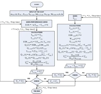
Fig. 6 shows steps for calculation of the heat pump cycle with the simplified model. Performance correlations of the EERVCHP with the operating temperatures are given. The inputs data are the operating conditions and the useful hot water temperature profiles. The upgraded hot water temperature in hot water tank and leaving condenser are the outputs of calculation.
Fig. 7 shows the simulated results of the EERAC and the
heating capacity at condenser during (QC) when hot water in
tank is used at the steady state condition of useful hot water flow rate around 0.03 L/s. EERAC and QC are nearly constants
at hot water temperature in the storage tank constant at around 55 ºC. The simulated results agree well with the measured data. It could be seen that the simplified models could be used to simulate the performances of heat pump system that is used to recover the waste heat from the discharge refrigerant of air-conditioner. Thus the model will be used to predict the possibility in using this concept for generating hot water in the department of children's hospital room, Maharaj Nakorn Chiang Mai. The details are given in the next part.
2.0 2.4 2.8 3.2 3.6 4.0
0.0 0.5 1.0 1.5 2.0 2.5 3.0 3.5 4.0
12:03:00 12:18:00 12:33:00 12:48:00 13:03:00 13:18:00 13:33:00 13:48:00
E
E
R
Q
C
(k
W
)
Time
Figure 7. Comparison results of the measured data and the simulation results of hot water temperature from R-290 VCHP.
4.4. Generating Hot Water by Useful Temperature Profile
Profile of hot water consumption in the department of children's hospital room, Maharaj Nakorn Chiang Mai Hospital is selected for the simulation. The required hot water consumption is around 815 L/d and the working temperature is about 50 ºC. The conditions for the simulation are as follows:
Profile of hot water consumption (mɺUG,t) is shown in
Table 4.
Initial temperature in hot water storage (TUG,S) is at 30 ºC.
Maximum temperature of heat pump (TUG,max) is 55 ºC.
Fill-in water temperature (THW,i) is at 30 ºC.
Hot water tank (VUG,Tank) is 300 L.
Heat loss of hot water storage tank (UAUG) is 5 w/m 2
. The ambient temperature (Tamb) is 30 ºC.
From the simulation, it could be seen that one unit of R-290 heat pump could recover waste heat from 1 unit of air-condenser to generate hot water in this hospital. Fig. 8
shows comparison of the temperature history during a day between R-290 heat pump and electrical heater when the storage tank is 300 L. Around 12-13 o’clock, there is a high rate of water consumption thus the temperature slightly drops down. Fig. 8 also shows the advantage point of R-290 VCHP which the average hot water temperature is higher than that of using the electrical heater. Moreover, R-290 VCHP consumes the electrical power at around 1/3 time compared with the normal electrical heater. Including that R-290 is the organic type of refrigerant which is friendly with the environment.
Table 4. Profile of using hot water in the hospital.
Time Quality (L) Flow rate (L/s)
8.00 105 0.029
9.00 25 0.007
10.00 65 0.018
11.00 50 0.014
12.00 60 0.017
13.00 165 0.046
14.00 70 0.019
15.00 110 0.031
16.00 140 0.039
17.00 25 0.007
Total 815 0.198
0 10 20 30 40 50 60 70
8:00 20:00 8:00 20:00 8:00 20:00 8:00 20:00 8:00 20:00 8:00 20:00 8:00 20:00
H
o
t
w
at
er
t
em
p
er
at
u
re
(
C
el
ci
u
s)
Time
Figure 8. The results of simulation from the hospital data in 84 h for storage tank 300 L.
4.5. Economic Analysis
For the economic result for generating hot water in the hospital, a simple payback of the hot water system from the waste heat of air-conditioner is compared with the unit having the electrical water heater for hot water generation. The details of general conditions for economic analysis are:
A. The operating day is 365 d/y. B. The operating time is 8 h/d.
During 9.00-22.00 o’clock is 1 h/d. During 22.00-9.00 o’clock is 7 h/d.
C. Electricity charge (Time of Use Rate: TOU) are as: During 9.00-22.00 o’clock is 0.1144 USD/kWh. During 22.00-9.00 o’clock is 0.0677 USD/kWh. Ft (Fuel adjustment charge at the given time) is 0.0215 USD/kWh.
Peak demand charge is 9.7104 USD/kWh·m. D. Maintenance cost is 3 % of initial investment.
unit uses the electrical power consumed around 1.18 kWe
while that of the electrical heater is 3 kWe. Thus the payback
could be calculated by:
Payback period = Total investment / Annual saving. (15)
Table 5 shows the economic results for using R-290 VCHP to produce hot water temperature around 55 ºC compared with the conventional heater. It could be seen that the saving cost of the electrical power consumption from using R-290 VCHP compared with the electrical heater is around 765.46 USD/y [13] and payback period of the modified system is around 1.94 y.
Table 5. The economic results for using R-290 VCHP and the electrical heater.
Descriptions R-290 VCHP Electrical heater
The electrical power consumption (kW)
1.18 3.00
Operating time (h/d) 8.00 8.00 The rate of electrical power
(kWh/y)
3,445.60 8,760.00
Cost of the electrical power (USD/y)
496.28 1,261.74
Investment cost (USD) 1,551.85 155.19 Payback period (y) 1.94 -
5. Conclusions
From the study results, the conclusions are as follows: 1 R-290 is selected as the working fluid for the heat pump
in term of its high efficiency and the environmental impact.
2 The air-conditioner with spiral coil tank and heat pump gives better EERAC when the cooling water is not over 43
ºC.
3 The simulated results agree quite well with the measured data.
4 For the hospital at required hot water 0.815 m3/d and 50 ºC, the saving cost and the payback period of R-290 heat pump are 765.46 USD/y and 1.97 y, respectively.
Acknowledgements
The authors would like to thank the School of Renewable Energy, Maejo University for supporting testing facilities. Highly acknowledge to the TSUS Innovation Intelligence Ltd for the budget support.
Nomenclature
A Area, (m2)
Cp Specific heat capacity, (kJ/kg·K)
h Enthalpy, (kJ/kg)
mɺ Mass flow rate, (kg/s)
N Number, (Unit)
P Pressure, (bar)
Q Heat rate, (kW)
R Refrigerant, (-)
v Specific volume, (m3/kg)
V Volume, (m3)
s Entropy, (kJ/kg·K)
t Time, (s)
T Temperature, (ºC)
U Overall heat transfer coefficient, (W/m2·K)
W Work, (kW)
Greek Symbol
η
Efficiency, (%)Subscript
a Air
AC Air-conditioner
amb Ambient
C Condenser
Comp Compressor
CW Cooling water
da Dry air
dif Difference
e Electrical
E Evaporator
FC Fan coil
H High
HS Heat source
HW Hot water
i Inlet
L Low
max Maximum
min Minimum
o Outlet
ref Refrigerant
S Start
SP Spiral coil
SW Supplied water
Sys System
th Thermal
U Used
UG Upgraded
VCHP Vapor compression heat pump
W Water
References
[1] N. Chaiyat, C. Chaichana, “Working fluid selection for geothermal heat pump”, Engineering Journal Chiang Mai University, 2006, 13: 27–32.
[2] N. Chaiyat, T. Kiatsiriroat, “Recovering and upgrading waste heat of air-conditioner by combining R-123 vapor compression heat pump,” In: Proceeding of the 9th Conference on Energy Heat and Mass Transfer in Thermal Equipment, Prachuap Khiri Khan, Thailand, March 11–12, 2010.
[3] F. S. Singharajwarapan, N. Chaiyat, “Vapor compression heat pump using low temperature geothermal water: A case study of northern Thailand”, In: Proceeding of the 10th Asian Geothermal Symposium, Tagaytay, Philippines, September 22–24, 2013.
[5] S. K. Chou, M. N. A. Hawlader, J. C. Ho, N. E. Wijeysundera, and S. Rajasekar, “Heat pump in the drying food products”, The Science and Technology Information Network of the Philippines, 1994, 8: 1–4.
[6] S. Clements S, S. Jia, P. Jolly, “Experimental verification of a heat pump assisted continuous dryer simulation model”, International Journal of Energy Research, 1993, 17: 19–28. [7] G. S. Young, S. Birchall, R. L. Mason, “Heat pump drying of
food products prediction of performance and energy efficiency”, In: Proceeding of the 4th ASEAN Conference on Energy Technology, Bangkok, Thailand, October17–20, 1995. [8] A. Sadchang, “Design and construction of heat pump dryer prototype for small industry,” Master Engineering Dissertation, Chiang Mai University, Chiang Mai, Thailand, 2006.
[9] M. Burapha, T. Kiatsiriroat, “Simplified model of solar water heating with heat pump assisted”, The journal of industrial technology, 2008, 2: 15–23.
[10] American Society of Heating, Refrigerating and Air-Conditioning Engineers, Inc, “ASHRAE Handbook fundamentals,” Refrigerant, American, 2009.
[11] Properties of R-32, <http://www.refrigerants.com/> [Accessed 1 June 2014].
[12] Properties of R-410a, <http://www.nationalref.com/> [Accessed 1 June 2014].