Published online January 17, 2015 (http://www.sciencepublishinggroup.com/j/jeee) doi: 10.11648/j.jeee.s.2015030201.11
ISSN: 2329-1613 (Print); ISSN: 2329-1605 (Online)
The feature of underground channel for the wireless
underground sensor networks
Farzam Saeednia
1, *, Shapour Khorshidi
2, Mohssen Masoumi
31Department of Electrical Engineering, Kazerun Branch, Islamic Azad University, Kazerun, Iran 2Air-Sea Science and Technology Academic Complex, Shiraz, Iran
3Department of Electrical Engineering, Jahrom Branch, Islamic Azad University, Jahrom, Iran
Email address:
[email protected] (F. Saeednia), [email protected] (S. Khorshidi), [email protected] (M. Masoumi)
To cite this article:
Farzam Saeednia, Shapour Khorshidi, Mohssen Masoumi. The Feature of Underground Channel for the Wireless Underground Sensor Networks. Journal of Electrical and Electronic Engineering. Special Issue: Research and Practices in Electrical and Electronic Engineering in Developing Countries. Vol. 3, No. 2-1, 2015, pp. 1-5. doi: 10.11648/j.jeee.s.2015030201.11
Abstract:
The propagation characteristics of Electro Magnetic (EM) waves in the soil and also the significant differences between the propagation in the air prevent us from obtaining one direct feature for Wireless Underground Channel. In fact, the underground environment consists of soil, rock and water instead of the air. The challenging reasons of these environments to propagate the wireless signal via the Electro Magnetic (EM) 1 waveguides are considered as: the high path loss, channel dynamic conditions and the high size of antenna. In this study, the details of Bit Error Rate (BER)2 for 2PSK modulations, path loss and the bandwidth of the Magnetic Induction (MI) 3Systems in the underground environment via one small induction coil were evaluated .At the end of this study, a general framework is obtained about the wireless underground communications and wireless underground sensor network. It is concluded that using the proposed framework, the transmission range in MI waves system would be raised and the path loss in that system would be declined severely.Keywords:
Channel Modulation, Electro Magnetic, Magnetic Induction1. Introduction
The Wireless Underground Sensor Networks (WUSNs) have the wireless sensors that are buried underground. WUSNs have so many applications such as the coverage, easy to use, appropriate data, reliability and the cover density. The other applications are the control of the soil conditions, earthquake, landslides forecast, the underground substructures control, the landscapes management and security [1, 2].
It can be mentioned that the underground propagation environment consists of soil, rock and water instead of the air that confront us with three challenges if it is applied for the wireless communications via the Electro-Magnetic (EM) Waves: The high path loss, channel dynamic conditions, and the antenna size [3].
Akyilidizet.al, [2] evaluated the challenges of wireless underground sensor networks environment and Lilli et.al, [3] evaluated the features of the underground channels for the wireless underground sensor networks The magnetic induction was applied for the first time by Jack et.al, [4] in
the wireless underground sensor networks [4].
The objective of the present study is to present a general framework for the wireless underground communications and WUSN that the transmission range in MI waves system would be raised and the path loss in that system would be declined severely.
The structure of this study is as follow: in the next section, the conditions of underground channel are evaluated to analyze the same channel conditions via the theory. In section three, the simulated proofs of the section two are presented and some comparisons are considered at the end. Finally, the conclusion is presented.
2. The MI Channel Properties
combination of operational frequency and soil. Thus, as the operational frequency decreases, the path loss is decreased too but we need a larger antenna [3]. One suggested solution is to apply some antenna with 0.3m length to receive 300 MHz signals. Meanwhile, the signal transmission range of these antennas is about 4 meters. Recently, the Magnetic Induction method has been used as a new physical layer method for the wireless communications but it has disadvantages such as the high path loss and Low bandwidth. According to the previous studies, the MI transfer hasn’t been influenced by the soil type, compositions, concentrations or the moisture rate [5].
2.1. Channel Modeling
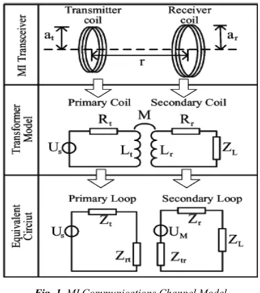
In the MI communications, the transmitting and receiving is conducted via the induction coil (first row in fig.1). Meanwhile, at , ar are the radiuses of transmitting and
receiving respectively. r is also the distance between the receiver and transmitter. For example, the sinusoidal current
= . is a signal that is found in a the transmitter coil whereas, = 2 is the angular frequency of transmitter signal and f is the operational frequency of system. This current is able to induce another sinusoidal current in the receiver and make the connection possible. The interaction between the two paired coils is indicated by the mutual inductance. Thus, MI receiver and transmitter can be modulated as the Primary and Secondary Coil Loops of one converter (Transformer Model). As it is shown in the second row of fig.1, MI is the mutual inductance of the receiver and transmitter coil.
Fig. 1. MI Communications Channel Model
Us is the battery voltage of the transmitter, LT , Lr are the
self-induction , RT, Rr are resistance of coil and ZL is the
impedance of the receiver load. The third row in fig.1 indicates the analysis of the converter (transformer model) .
= + ∗ = (1)
= +! ∗ = +
"#= − ! +"%
Whereas, Zt, Zr are the impedance (impedance-based axis)
of the receiver and transmitter coil .Zrt is the effect of
receiver on the transmitter but Ztr is the effect of transmitter
on the receiver .Uµ is also the inductive voltage of the receiver coil loop . Both the receiver and transmitter powers are the functions with the transmission range, r.
P'(r* = Re -2../∗01
3
4 .3 ./56 (2)
P7(r* = Re 8ZU: 7+ Z7<=
With regard to the Transmission Line Theory, the reflection is neutralized by the same impedance. In order to increase the received power, the load impedance is equal to the conjugate of impedance in the secondary loop output obtained from the Equ.3 as follow:
(3)
According to the Equ.4, the analysis of coil resistance can be determined via the material resistance, size and the number of turns of coil.
R7= N7∗ 2πa7∗ R (4)
R'= N'∗ 2πa'∗ R
In the equ.4, Nt, Nr are the number of turns for the
transmitter and receiver loop coils respectively.R0 is the
resistance of unit length for one loop as one magnetic dipole that is written for the various wire diameters as 3Ω/DJK 2 ∗
10 GΩ/D on the basis of American Standard (AWG) . The self-induction and induction can be inferred via A Magnetic Dipole Potential. The different dipole systems have been considered in [7].
A(r,θ,ϕ* =Gµ
π'πa7I e
KL7 sinθPQ−K( π*
λ R . aϕ (5)
Whereas, µ is the magnetic permeability of transfer environment and λ is the signal wavelength. With regard to the Stokes Theory, the mutual inductance of two coil loops can be written as follow [7]:
M = (N ∮ A . dI[3 '*/dI ≅µπWXW '32YZXY35 (6)
The self-inductance is calculated as :
≅Q\ ] ^ ≅Q\ ] ^ (7)
transferring environment consists of various kinds of soil, water, rock, etc. Thus, the analysis of permeability differences between these materials is necessary [8]. Generally, the materials inside the underground environments can be divided in to 4 basic groups: organic materials, mineral materials, air and water. The organic materials consist of the plants and animals that live in the environment. The relative permeability in the flower, plant, air and water is nearly 1 and if the sand and clay don’t have any magnetic, their relative permeability will be nearly 1. For example, the permeability of the Sedimentary rocks is about 1.009 [8]. Since most parts of the soil are without magnetic, it is supposed that the relative permeability in the underground environment is constant and it is according to the above mentioned concepts.
2.2. Path Loss
In order to have a wireless communication with the EM waveguide, the received power by the antenna will be obtained via the Frazer transport Equation [9]. The Irradiation Power is the most important consumption factor for EM waveguide transmitter. Although the transmission power 1(Pt) in the EM waveguide system is a constant power
that isn’t influenced by the receiver position, the LEM path
loss in the soil environment is calculated as the received power to the transmission power [3]:
_ (`* = −10 abcd ( *de = 6.4 + 20abc` + 20abch + 8.69k` (8)
Attenuation constant of α waves and phase-shift constant of β waves are 1/m and Radian/m respectively. While, the transfer distance r is determined by meter, it depends on the dielectric characteristics of the soil. Also, the other air-ground interface reflection isn’t considered because of high penetration [3]. If we attempt to prevent from wasting the transmission power due to radiation to the environment, we should use MI communication system because it is possible to ignore the irradiation power as the radiation resistance is negligible. It causes that the transmission power of MI system is consisted of the consumed power in MI receiver and the consumed power in the coil loop resistance .Meanwhile, since the coil loop resistance is negligible, the received power to the transmission power is close to one and the transmission power is restricted. As a result of this, the most favorable power is transferred in WUSN system but the path loss still exists. Thus, the received and transmitted power increase simultaneously as the transfer distance is raised. In order to compare the operation of EM waveguide system and MI system, the path loss in MI system with the transfer distance, r is defined as follow.
Lm[= −10 log(qqX3('('*r**, Whereas P'(r*is the received power ratio at the receiver that is r meter away from the converter. P7(r * is the source transmission power when the
transfer distance is very limited. P7(r * ≅0s
tX is considered
when r0 is small . When the coil resistance is low (R ≪ ωμ)
and the frequency is high, the path loss of MI information system is summarized as follow:
Lm[(r* = −10 lgqqX3('('*r*≅ −Q xyW3YX
ZY3Z
GWX'z = 6.02 + 60 lg r + 10 lg WX
W3YXZY3Z (9)
In order to analyze the path loss of MI, EM waveguide systems in the underground environments, equations 8 and 9 were compared. In equation8, there are two path losses, one of them is related to the transfer environment 20ac` and the other is related to the materials absorption 8.69k` which both of them have important effects on the path loss. However, no soil dielectric materials such as α & β is found in equ.9. So, no clear effect is seen on the MI path loss. The only path loss in equ.9 is60ac` that is due to the extent of propagation environment. However, the propagation in the underground environment has no effect on the path loss. The reason is the constancy of underground materials permeability. Although the path loss due to 60ac` in MI system equation is much more than the path loss due to
20ac`in EM waves, it is created because of another factor in the equation of EM waves system as 8.69k` that makes great loss from the propagation in the underground environment.
3. Numerical Analysis
3.1. Path Loss
The path loss in the MI, EM systems in Equation8 and Equation 9 were evaluated via MATLAB software. The results are shown in fig.2. The EM wave’s propagation in the soil environment is influenced by the soil characteristics especially the amount of water in the soil (VWC). Thus, we indicate VWC in the soil environment as 1%, 5% and 25% [3].
In our simulation, along by VWC, the collection of soil composition is determined as follow: the percentage of sand(S) 50%, the percentage of clay(C) 15%, mass density ({|)1.5 grams/cm€, density of the solid soil particles (ρs) 2.66
y'Y•:
‚•Z that are considered as the normal values [3]. The
permeability of the underground transmission environment is constant and applied in the air .4π ∗ 10 ƒ „
•.
Meanwhile, other simulation parameters for EM system are also act the same. The operational frequency is set on 300MHZ. there are two reasons for selecting this frequency: 1.The path loss in this frequency is acceptable and in the frequencies lower than 300MHZ, the path loss will be raised. 2 .as the operational frequency is reduced to below 300MHZ, the size of antenna will be raised but it prevents from WUSNs implementation.
For MI system, the receiver and transmitter coil loop has a same radius (0.15) and the number of turns of coil is 5. The coil loop has been made by the cooper wire with 1.45 mm diameter. Thus, the resistance of unit length R0 can be
of turns of coils can decrease the influence of parasitic capacitance effectively [10].As it is shown in fig.2, the path loss in MI system and EM wave system has been indicated as dB against the transmission distance with the different soil, VWC. As expected, the path loss in MI system is not influenced by the environment because the permeability, µ remains the same in the whole propagation environment. On the other hand, as VWC increases, the path loss in EM waves system is also raised severely. When the soil is very dry (good insulation), VWC=1%, the path loss of EM waves is lesser than MI system. When the soil is very wet (good
conductor), VWC=25%, the path loss of EM waves is much more than MI system [12]. When the moisture of soil is as VWC=5%, the path losses are same for two systems. The main reason of path loss in EM wave system is the absorption of EM transmission waves inside the underground materials. When the amount of water in the soil is VWC=5%, the EM wave system has the lowest path loss in the range of 0.5m to 3m. In relatively remote areas, r>3m, MI system has the lesser path loss than EM system .Even in MI system; it has the lesser path loss than EM wave system in remote distances.
Fig. 2. The path loss of EM waveguide system and MI system is different from the soil water content.
Fig. 3. Bit Error Rate for EM wave system with different soil water content and MI system with noise.
3.2. Bit Error Rate
As it was evaluated, the characteristics of BER(fig.3) depends on three factors: 1. Path Loss 2. Parasite Level 3.Modulation Method used by system. The path loss in MI system and EM wave system has been considered in Equation 8 and Equation 9. The parasite power in the soil
was measured by wireless spectrum analyzer (BVS yellow jacket) [3] and [11]. The mean of noise level Pn was
considered as about -103d B m and -83d Bm. The signal to noise (SNR) 1 can be calculated by SNR=Pt-L-Pn whereas Pt
id the transmission power and L is the path loss (Equations 8 and 9) . In the simulation, Pt=10 dBm was considered. 2PSK
modulation with the simple design was used while it is applied extensively. BER was obtained on the basis of a SNR function: BER = 0.5er fc(√SNR (in this function,
erfc(√‹] ) is the error function [24]. In fig.3, BERs in MI and EM systems were shown with the different VWC soils as a function of transmission distance, r. In the low noise scenario, the transmission range in MI system is more than EM wave system (regardless of VWC). This scenario is explained via the following reasons:
A. In the low noise, the path loss below 100d B has no effect on the operation of BER.
B. MI system has more path loss than EM system in the sections that are below 100d B. But the path loss in this system is lower in the sections that are more than 100d B.
can influence on the operation of BER.
Fig. 4. The Frequency Response of MI Waveguide System with Different Wire and Remote Relay Resistances.
3.3. Bandwidth
It must be mentioned that the path loss in MI system is created because of the following factors: only one central frequency can make the load impedance matching possible but the output impedance is originated from resistance and reactance. The load impedance should be equal with the impedance conjugation of output in the secondary loop to prevent from any deviation in the central frequency that causes the reflection of transmission power and the increase of path loss. According to the analyses, the bandwidth ratio in MI system with the different transmission distances (fig.4) is 3-dB that is about 2KHZ. When the operational frequency is 10MHZ, the bandwidth isn’t influenced by the transmission distance. Thus, MI system provides the wider range (10m) than EM waveguide system (about 4m). The advantage of MI system is that its operation is not influenced by the environment characteristics of soil especially the water content. But the transmission range of both systems is still too short to use for the scientific applications in the underground environment [2].
4. Discussion and Conclusion
In the underground wireless communications via EM waves, there are three major challenges: the high path loss because of the material absorption, the channel dynamic conditions because of the various properties of the soil and the very high size of the antenna.
MI is an alternative method with the same channel conditions and it can accomplish the communications with the small loops but recently, no detailed analysis performed to evaluate the path loss and the bandwidth of MI system in the underground soil environment. At the present study, one analytic model was shown that indicated the
communicational underground channel characteristics of MI. According to the channel analysis, we presented one MI wave method that increased the transmission range. Our analysis indicated that MI method had the constant conditions of channel because the path loss only depends on the permeability of propagation environment but the materials absorption is one of the most important parts in the path loss of EM system that may change in the various soil conditions. In the underground environments, the path loss of MI system is slightly lower than EM wave system in the natural and wet soils.
References
[1] I. F. Akyildiz, W. Su, Y. Sankarasubramaniam, and E. Cayirci, “Wireless sensor networks: A survey,” Comput. Netw. J., vol. 38, no. 4, pp. 393–422, March 2002.
[2] I. F. Akyildiz and E. P. Stuntebeck, “Wireless underground sensor networks: Research challenges,” Ad Hoc Networks (Elsevier), vol. 4, pp. 669–686, Jul. 2006.
[3] L. Li, M. C. Vuran, and I. F. Akyildiz, “Characteristics of underground channel for wireless underground sensor networks,” presented at the Med-Hoc-Net’07, Corfu, Greece, Jun. 2007.
[4] N. Jack and K. Shenai, “Magnetic induction IC for wireless communication in RF-impenetrable media,” presented at the IEEE Workshop on Microelectronics and Electron Devices (WMED 2007), Apr. 2007.
[5] A. R. Silva and M. C. Vuran, “Development of a testbed for wireless underground sensor networks,” EURASIP J. Wireless Commun.Netw. (JWCN) [Online]. Available: http://cse.unl.edu/~mcvuran/ugTestbed.pdf
[6] Standard Specification for Standard Nominal Diameters and Cross- Sectional Areas of AWG Sizes of Solid Round Wires Used as Electrical Conductors, ASTM Standard B 258-02, ASTM International, 2002.
[7] D. R. Frankl, Electromagnetic Theory. Englewood Cliffs, NJ: Prentice- Hall, 1986.
[8] W. M. Telford, L. P. Geldart, and R. E. Sheriff, Applied Geophysics, 2nd ed. New York: Cambridge Univ. Press, 1990. [9] J. D. Kraus and D. A. Fleisch, Electromagnetics, 5th ed. New
York: McGraw-Hill, 1999.
[10] L. A. Charles and W. A. Kenneth, Electronic Engineering, 3rd ed. New York: Wiley, 1973.
[11] “YellowJacket Wireless Spectrum Analyzer,” Berkeley Varionics Systems, Inc. [Online]. Available: www.bvsystems.com