1. Introduction
Global and sustainable solutions are now very important [1]. In this context, alternative energy solutions are needed because the non-renewable energy sources are consumed extensively [2]. In this sense, it is necessary to have an environmentalist and sustainable understanding to leave a useful world for future generations [3,4]. The discipline of architecture, especially in this area, must be much more rigorous than other disciplines [5]. Because in the process of building construction and afterwards serious energy is used [6]. Finding and using solutions by increasing the
proportion of energy used can be met with renewable resources is a matter that should be emphasized on today's architecture [7,8]. Sun, an important source of renewable energy sources, has been an important source of inspiration for architects seeking solutions that are environmentally friendly and respectful to nature in the design process [9]. Our country has a very high potential in terms of utilizing solar energy [10]. "It has been emphasized that using solar energy from buildings is primarily through design and at the very beginning of architectural design processes, with decisions based on scientific subdivisions [11,12].
Click here, type the title of your paper, Capitalize first letter of each words
First Author
a, Second Author
b,*a
First affiliation, Address, City and Postcode, Country b
Second affiliation, Address, City and Postcode, Country
Journal of Solar Energy Research 23 (2017) 27-31
Solar Envelope Method and Consideration of the Effectiveness of
Construction Density and Settlement in Konya
Asmaa Ahmed Mustafa JAFF
a*aSelçuk University, Faculty of Architecture, Konya, Turkey
, Email: [email protected]
Journal of Solar Energy Research (JSER)
Journal homepage: www.jser.ut.ac.ir
A B S T R A C T
Nowadays, the acceleration of environmental problems as much as possible and the preservation of the environment for this reason become an increasing concern; we have required architects to use different design alternatives in their designs. For this reason, many developed countries in recent years have an economic vital significance in the energy use performance of constructions. From this point of view, it seems that ecological architecture based on the use of environmentally sustainable energy resources based on energy efficient design is preliminary and widespread.
In this study, solar envelope method was used for healthy sunbathing in residential areas and an experimental model analysis was performed. The analysis is based on a residential area in the Kosovo neighbourhood, which is connected to the Seljuk district of the Konya city. Within the scope of the study, the solar shells were formed separately for the two different suggestions prepared as a result of the current state of the structure island and the analyses made. The resulting solar shells that has been tried to be used efficiently by volume, the coefficient of the island structure was fixed floor space and increasing the number of shells suggestions to the sun and the height of blocks in a particular order. Solar envelope data obtained using the methods and results of comparisons made between the current state recommendations.
© 2017 Published by University of Tehran Press. All rights reserved.
ARTICLE INFO
Received: 16 July 2017 Received in revised form: 30 July 2017
Accepted: 14 Aug 2017 Available online: 5 Oct 2017
Keywords:
28 2. Materials and Methods
In this study, in buildings using solar Envelope method it is intended to benefit from the sun at the highest level. With this method, the sun moves in a certain plane and reveals the idea of shaping the building forms in the direction of this layout. With the form to be built, the sun can benefit from the highest level and the negative effect of the resulting shadow can be minimized.
Solar Envelope certain (t) in the time frames are volumetric boundary of a building to create a shadow over the neighboring buildings in the immediate vicinity. Forming solar Envelope in a land and in buildings designed while remaining within the limits of the shell, adjacent buildings will drop shadows to our design takes our buildings with, the amount of sunbath will be increased.
The sun, which is the unexhausted source of energy in our world, must also be a source of the shaping of cities and architecture. In the Solar Envelope method, the geometric basis is taken. The shape of the space, the shape of the building, and the angle of sunlight are the factors that feed the foundations of this geometry. This method is produced using a three-dimensional thinking system. While creating Solar Envelope, AutoCAD, Sketch Up, 3D Max and so on. Modeling programs can be used.
Space and time are two key influences in the formation of Solar Envelope. Time is related to the unwillingness of sunrise to occur at what time of the day, and to which season we want to make more use of the sun. The space factor is linked to the buildings and areas around the land we will design. Solar Envelope 's shape works in connection with environmental spaces and other areas around the land. We will design with the space factor, and the boundaries of the buildings' shadows will be determined. It is taken from the daily movement of the sun and taken as reference for 12.00 hours. In the Solar Envelope method, the duration of sunbathing is determined by taking equal hours before and after lunch.
For the summer and winter seasons, Solar Envelope is created at the specified time interval and a shell is formed by these two. For the winter season, sunbathing is provided between 10: 00-14: 00 on the 21st of December, and between 10: 00-14: 00 on the 21st of June. Before and after the afternoon, the coordinates of the sun with the land and the coordinates where the land is determined are determined. The resulting triangular surfaces are intersected before and after the afternoon, and these surfaces are joined together into a volume.
The solar envelope is a construct of space and time: the physical boundaries of surrounding properties and the period of their assured access to sunshine. These two measures, when combined, determine the envelope’s final size and shape [14].
First, the solar envelope avoids unacceptable shadows
Figure 1: Formation of Solar envelope [13] above designated boundaries called ‘‘shadow fences’’. The height of shadow fences can intentionally respond to any number of different surrounding conditions, such as windows or party walls. Their height may also respond to adjacent land-uses, for example, with housing demanding lower shadow fences than commercial or industrial uses. Different heights of shadow fence result in contrasting shapes and sizes of the solar envelope (Figure. 2, left). Second, the envelope provides the largest volume within time constraints, called ‘‘cut-off times’’. The envelope accomplishes this by defining the largest theoretical container of space that would not cast off-site shadows between specified times of the day. Greater periods of assured solar access will be more constraining on the solar envelope than shorter periods (Figure. 2, right).
Figure 2: Space–time constraints: shadow fences may have different heights on adjacent properties to avoid overshadowing such elements as windows or rooftops that could benefit from direct sunshine (left); specifying different cut-off times can increase or decrease volume under the solar envelope because of changed sun angles (right). [15]
3. Case Study
3.1 Residence Hill Site
Residence Hill Site is located on the New Istanbul cemetery in the Kosovo neighborhood of the Seljuks municipality.There are settlements around the site. Residence Hill is the site with an area of 12963 m 2, consisted of two populations A1, A2, A3, A4 and B1, B2, and B3 are to be 7 blocks.Blocks A and B are adjacent to each other.
direction.There are 2 Z + 7 story buildings in the building island.
Figure 3: Workspace Bird's Eye Look
Figure 4: Towing distance of Protected Area Solar shells for analysis were produced by taking into account the existing buildings in the study area. The base areas of the solar shells are determined by considering the other land and the building boundaries on the existing land.
Floor area of the proposed building mass is determined while maintaining the current land value of the FSI. The floor height of the proposed masses was determined as 3 meters and the water pressure as 0.5 meters.
Figure 5: East direction (personal archive)
Figure 6: Western direction (personal archive)
Figure 7: North direction (personal archive)
30 3.2 Determination of Time Parameter
The degree of latitude Konya, for the winter period, when the south oriented perpendicular to a surface power density and considering insolation time clock 9 to 15 with the clock 10 to 14, between the two-time intervals in which the sun of the start and end time is appropriate. When set to sunshine duration of 9 to 15, the amount due to the low density of the structure value of the solar elevation angle will decrease.11 - 13 from uninterrupted sunshine duration is an inappropriate range is too short. Taking into account the criterion of building density, it is appropriate to choose between 10 and 14 o'clock, with respect to other time intervals, time and solar energy intensities coming from the surface. (3)
Table 1: December 21st, 21 June angular coordinates (4)
Figure 9: Residence Hill Site Available Situation plan
Figure 10: Residence Hill Site Reconstruction Data
Figure 11: Knock outing created by Shell Solar and Residence Hill Site for Current Settlement Blocks
4. Application of The Selected Specimen Surgical Method And Evaluation of The Data Obtained
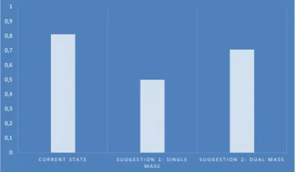
The area of the selected sample structure is fixed to the area where the Base Area Coefficient (FSI) specified in the image can be used. This area was calculated over single and double suggestions. (Figures 6 and 7)
Figure 8 is a graphical representation of the floor area coefficients (CAS) of the present situation and proposals. The unity, dual CAS value was found to be less than the current situation.
The mass of the building obtained as a single proposal is Z + 15 times. It is seen that the last 5 layers are formed by the inclined surfaces of the solar shell and turned out to be smaller layers than the floor area. In the case of binary proposals, the same method was applied in the sense of position. However, different CACS values were obtained because of the change in mass number. The two proposals have reached Block A + Z + 15 kata. It has been affected by the solar shell and has undergone deformation for the last 11 times and remained in lower areas. B block is Z + 8 times. The number of floors that are subject to spatial deformation is 4.
Figure 12: Proposal for a single Mass prepared in selected areas
Figure 13: Recommendations for selected Binary Mass in the Field Prepared
Figure 14: CACS values of prepared Obtained from Present Situation and Suggestion
Block Numbers
Value
(FAR) Floor Categories Current
State 0,811 Z+7
Single Mass 0,499 Z+15
Dual Mass 0,706 Z+15 (A BLOCK) Z+8 (B BLOCK)
5. Conclusions
In the data obtained from the analysis study, it was concluded that the selected area should be reduced by 65% by volume when applied to the solar envelope based on a layout parallel to the current situation. Such a reduction would result in a collection of buildings that do not cast shadows around the building itself. In general, it is better to choose a settlement in the south direction of the shell in order to make maximum use of the volume formed by the solar envelope method. The singles, duets are positioned close to the south on the same course, adopting an appropriate understanding of this situation. Having a wide-open space in the north direction of the selected area (boulevard) caused the crust to grow longer in size in the north and south axis of the crust. Thus, the blocks were placed at the northernmost point of the road, before the shell was exposed to the broken part in the north. On this side, we have obtained a southern garden where the three sides are sealed, isolated from the negative north wind and to which we can make maximum use of the sun. Both the solar envelope method was applied and the southern part of the land was used as open space
References
[1] Givoni, B. (2000). "Man, climate and architecture", Applied Science Publishers, London, UK.
[2] Givoni, B. (2009). "Climate considerations in building and urban design", Van Nostrand Reinhold, New York, USA.
[3] Fuchs, M., Hegger, M., Stark, Th., Zeumer, M. (2008). Energy Manual: Sustainable Architecture (Construction Manuals), Birkhäuser Architecture.
[4] Cimino, J., (2009) “Milpitas Unified School District Sustainability Program.” Presented at Milpitas Unified School District.
[5] Contal,, M., Revedin, R. (2009)."Sustainable design: Towards a new ethic in architecture and town planning", Berlin: Birkhauser-Edition detail.
[6] Guzowski, M. (2012). "Towards Zero Energy Architecture: New Solar Design", Laurence King
[7] Adalberth, K. (1997). "Energy use during the life cycle of buildings: a method", Building and Environment, vol. 32, no. 4, pp. 317-320.
[8] Boyce, PR. (2010). "The impact of light in Buildings on Human Health: Indoor Built Environment"
[9] International Energy Agency: Daylight in Buildings, A Source book on Daylighting and Systems and Components. A Report of IEA SHC Task 21/ECBCS Annex 29, July 2000, pp. 5-11.
[10] Ander, D. (2014). "Daylighting", Updated by U.S. Department of Energy Federal Energy Management
Program (FEMP), Available at:
http://www.wbdg.org/resources/daylighting.php
[11] D. Klaus, "Advanced Building Systems: A Technical Guide for Architects and Engineers", Basel 2003. [12] Canan, F. (2008). A Model Test for the Control of
Parameters in Energy Efficient Design, Ph.D. Thesis, Selcuk University, Institute of Science, Konya. [13] Canan, F. and Copper Rel. (2008). Determination of
Concentration Densities in Mass Housing Areas by Sunshine.
[14] K.M. Kensek, R.L. Knowles (1997), Solar access zoning: computer generation
of the solar envelope, in: Proceedings of the ACSA SW Regional Meeting, University of New Mexico, Albuquerque, NM
![Figure 1: Formation of Solar envelope [13]](https://thumb-us.123doks.com/thumbv2/123dok_us/8945167.1854535/2.595.320.536.390.448/figure-formation-of-solar-envelope.webp)