0 INTRODUCTION
The environmental problems caused by harmful gas emissions of the vehicles remain significant issues requiring further investigation. To minimize this pollution, research on the efficiency of the vehicle in terms of the engine and transmission systems is increasingly common.
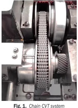
The continuously variable transmission (CVT), shown in Fig. 1, is one of the best solutions to reduce the fuel consumption for vehicles that are driven by internal combustion engines [1], electric motors [2], and hybrid systems [3]. This is a result of the CVT systems providing smoothness in changing of speed ratio, resulting in reduced fuel consumption for the vehicles. Moreover, CVT systems are significant and advantageous alternatives in the machinery industry when continuous speed variation is required. Mangialardi and Mantriota [4] analyse the dynamic behaviour of a wind power system equipped with automatically regulated, continuously variable transmission. Yildiz and Kopmaz [5] propose a novel mechanical press concept that consists of a
half-toroidal continuously variable transmission (CVT) to obtain more speed flexibility than the classical one. Yildiz et al. [6] analyse the dynamic behaviour of a four-bar mechanism coupled with a CVT system. Thus, the speed variability which is crucial for obtaining different manufacturing and transportation processes can be provided by mechanically.
To obtain better transmission performance, the dynamics of the transmission must be fully understood. Determining the dynamics of CVT is crucial to obtaining and controlling the desired the speed ratio accurately.
In this type of variator, the positions of the pulleys are varied by a hydraulic system, which results in a change in the contact radii of chain at the drive and driven sides; thus, the desired value of the transmission ratio is obtained. All these dynamic phenomena have been studied for decades. In particular, the theoretical analyses for both steady-state and transient cases have been studied in depth by Carbone, Mangialardi and Mantriota [7] and Yildiz et al. [8].
A theoretical model of the shifting dynamics of a chain CVT during rapid ratio speed changes
Control-Oriented Modelling with Experimental Verification
and Design of the Appropriate Gains
of a PI Speed Ratio Controller of Chain CVTs
Yildiz, A. – Kopmaz, O. Ahmet Yildiz* – Osman Kopmaz
Uludag University, Engineering Faculty, Mechanical Engineering Department, Turkey
The continuously variable transmission (CVT) system represents one of the best solutions to minimize the fuel consumption for vehicles that are driven by an internal combustion engine or an electrical motor. Hence, the theoretical analysis of a chain CVT is crucial in the optimization of the design and control strategy. This paper is concerned with the transient dynamics of a chain CVT with a speed ratio controller adopted from the Carbone-Mangialardi-Mantriota model and its experimental verification. To this end, a theoretical model is developed with a PI speed ratio controller, considering the momentary solution of a first order differential equation governing the shifting speed, which represents the whole dynamics of the CVT. To verify the developed model, the experiments are carried out on a chain CVT test rig. It is observed that the numerical and experimental results are in good agreement, which implies that the developed model embedded in a speed ratio controller is appropriate to predict the shifting dynamics of the chain CVT. Afterwards, the developed model is used to design the appropriate PI gains by numerical experiments in order to obtain the same slope of the time response of speed ratio for different input angular velocities. Therefore, the same shifting speed can be secured for the different working conditions in this manner. This paper contains very important results for manufacturers about the control parameter and gain effect on the shifting dynamics of chain CVT, and the developed model can be used for different control algorithms in automotive applications.
Keywords: chain CVT, speed ratio control, PID, shifting dynamics
Highlights
• Obtaining a lookup table of the clamping force ratio under the steady-state condition from the theoretical model with experimental verification.
• Implementing this lookup table in the first order differential equation and feedbacking the speed ratio with a PI controller. • Comparison of the theoretical and experimental results of the time response of chain CVT with a controller.
is developed by Carbone et al. [7]. The clamping force ratio as a function of torque load and traction coefficient is derived in detail.
Fig. 1. Chain CVT system
Carbone et al. [9] demonstrate that the pulley bending has an important role in the dynamics of the variator. The sliding angle that is one of the main parameters in equilibrium equations varies if the pulley deformation is considered. Therefore, it is proved that neglecting the pulley bending causes errors. It is also shown that the shifting speed of the variator increases as the stiffness of the pulley decreases.
The dynamic behaviour of the CVT is investigated at a steady state and in transient conditions by Carbone et al. [10]. However, in their study, the shifting dynamics are examined under no-load conditions. To verify the proposed theoretical model, experimental investigations are performed. Furthermore, the slip of the variator that is one of the crucial issues of the mechanical behaviour is analysed and controlled for efficiency optimization in [11].
Controlling the speed ratio is one of the crucial issues of the CVT systems, and there are several methods to do so. The most common technique is the proportional-integrate-derivative (PID) controller. The controller design with PI(D) and their applications are examined in [12] and [13]. Moreover, PI and PID controllers tuning is investigated by Precup and Preitl in [14] for integral-type servo-systems to ensure strong stability and controller robustness.
Although extensive works have been performed on the steady-state performance and the mechanical behaviours of the variator, such as slip predictions, traction capacities, the efficiency [15] to [17], only a few studies focus on the shifting dynamics of the CVT [18] and [19] and the speed ratio control in real time. Furthermore, most researchers use semi-empirical
formulations in their model that can cause some errors in different applications.
This paper differs from the previous works in that the shifting dynamics of the CVT with a PI controller is fully modelled based on the Carbone-Mangialardi-Mantriota model, and its experimental verification is carried out. From the theoretical model, a lookup table of the clamping force ratios as a function of speed ratio and traction coefficient is obtained for fast implementation in the control algorithm. After that, a PI feedback control algorithm is designed considering the momentary solution of a first order differential equation governing the shifting speed, which represents the whole dynamics of the CVT. To verify the developed model, several experiments are performed by setting the clamping forces of the drive pulleys with a feedback PI controller in a real time Labview environment. The experimental results show good agreement with the theoretical ones obtained from the control-oriented model based on the Carbone-Mangialardi-Mantriota approach. After verifying the model, it is used to obtain the appropriate PI gains via numerical experiments. A PI gain schedule is proposed for the different angular velocity of the drive pulley, which affects the shifting dynamics sharply. This model may constitute the basis of the different CVT control strategies, in particular, the feedforward control algorithm.
1 MODELLING THE CHAIN CVT
In this part, the theoretical model of the speed ratio control based on the Carbone-Mangialardi-Mantriota model is presented. First, the main equations of this model are presented. After that, a control algorithm for the speed ratio control of the CVT is proposed. As presented in [7], the basic kinematic quantities and their relations are presented as follows.
The mass conservation law yields the following relation as the longitudinal elongation of the chain is neglected:
vr+ v ∂
∂ =
θ
θ 0, (1)
where vr and vθ are radial and tangential sliding velocity of the chain respectively.
The sliding angle ψ isdefined as;
tanψ =vθ. vr
(2)
The radial sliding velocity is calculated as:
vr = +R R c
+
−
∆ω β
β θ θ
( cos )
sin sin( ),
1 2
2 0
0
where R is the pitch radius of the chain, β0 is the non-deformed half-groove angle of the pulley, θc is the
centre of wedge expansion, ω is the angular velocity of the pulley, and Δ is the amplitude of the deformed groove angle given in [15].
The deformed half groove angle is determined as a function of local angular coordinate θ, which considers a uniform deformation Г of the pulley, given in [15]:
β β− 0= +Γ 0 5. ∆cos(θ θ− c). (4) The centre of wedge expansion can be estimated as follows:
tan
( ) sin
( ) cos ,
θ
θ θ θ
θ θ θ
α α c
p d
p d
=
∫
∫
0
0
(5)
where α is the contact arc extension and p is the force per unit longitudinal chain length (linear pressure).
a)
b)
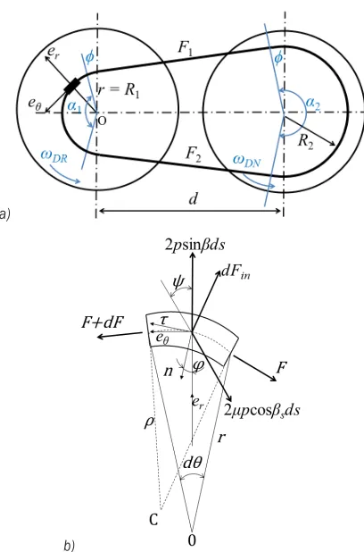
Fig. 2. The kinematic representation of a) chain CVT and b) the forces acting on the chain
All forces acting on the chain are represented in Fig. 2. The equilibrium equations in the radial and tangential direction yield the following equations:
1
2 2
2 2
0
F R F R
s
s −
∂
∂
(
−)
==
−
(
)
σ ω θ σ ω
µ β ψ
β µ β ψ
cos sin
sin cos cos , (6)
p F R
R s
= −
−
[
β σ ωµ β ψ]
2 2
0
2 sin cos cos , (7)
where F is the tension of the chain, and σ is the mass per unit length of the chain.
The angle βs satisfies the relation:
tanβS =tanβcos .ψ (8)
In the theoretical model, a friction coefficient
μ= 0.09 is implemented according to Coulomb friction.
Once the local pressure and tension distributions are known, the axial clamping force S and torque T
acting on each pulley are calculated as below:
S=
∫
(cosβ µ+ sinβS)pRdθ,α 0
(9)
T =(F F R1− 2) , (10)
where F1and F2 are the tensile belt forces at the entry and exit points of the pulley groove. In Eq. (9), the extension arc of the chain α can be calculated with the following relations:
sinφ =R R− , d
2 1 (11)
α1= −π 2φ, (12)
α2 = +π 2φ, (13)
where d is the distance of the pulleys’ centres.
The Carbone-Mangialardi-Mantriota model shows that the whole dynamics of the CVT can be represented as a first order non-linear differential equation as follows:
τ ω ξ
ξ
=
∆DR DR
eq
k g ln , (14)
where k= +(1 cos2 ) / sin
(
2)
,0 0
β β ξ =SDR/SDN and ξeq is the clamping force ratio at the steady state condition.
g(τ) and the logarithmic ratio of ξ and ξeq. The term g(τ)is as follows:
g τ τc τ
π ρ τ
τ
π ρ τ
τ
( )
= −+ −
− −
1
2 1
2 1
arcsin
arcsin
, (15)
where ρ(τ) = R / d and c ≈ 0.81.
Since the SDR / SDN is a function of the traction
coefficient and speed ratio, it is necessary to yield the traction coefficient μtr:
µtr β T
RS
=cos 0 .
2 (16)
In order to calculate the clamping forces ratio, the numerical steps are followed as shown in Fig. 3. A clamping forces ratio matrix is obtained by the same way for use in the control algorithm. This matrix is a function of the traction coefficient and speed ratio.
Fig. 3. Numerical flowchart for calculating the necessary clamping force ratio
2 SPEED RATIO CONTROLLER DESIGN
In order to control the speed ratio of the chain CVT, a PI controller is used, and the transient dynamics of the variator are investigated. In this controller, the initial condition of the angular velocity and the torque load of the drive pulley are given, and then the initial value of the clamping force ratio calculated by the theoretical model is implemented. For a constant clamping force of the driven pulley, the speed ratio is fed backed.
The program controls the speed ratio by changing the clamping force of the drive pulley while the new conditions calculated in CVT box spontaneously until it reaches the desired value of the speed ratio. Since the proportional pressure valves are much faster than the variator in terms of the time constant, the dynamics of the hydraulic system is neglected.
a)
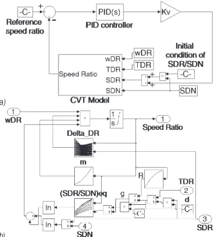
b)
Fig. 4. a) PI controller for the speed ratio and b) lookup tables
The error value between the desired set-point value τref and measured process variable of speed ratio
is:
e t( )=τref −τ( ).t (17)
The control variable, which is the voltage of the servo valve:
u t K e t
T e t dt
p i
t
( )= ( )+1
∫
( ) ,0
(18)
where Kp and Ti are the proportional gain and integral
The lookup table of the clamping force ratio {(SDR / SDN)eq = ξeq} shown in Fig. 4 is obtained
by the theoretical model, following the flowchart given in Fig. 3 for different speed ratios and traction coefficients in the range of 0.5 to 2 and 0.05 to 0.1, respectively. Another lookup table (m) is obtained from the relationship m(τ) = kg(τ) where k and g
given in Eq. (14) and (15). The pitch radius of the chain {R(τ)} is also given as a lookup table, which is calculated from Eqs. (11), to (13) and (24). The amplitude of the deformed groove angle {Δ(τ, SDR)}
is obtained from finite element FE methods [15]. The term Kv shown in Fig. 4 is the gain coefficient of the
valve and hydraulic system, which equals 13180. The parameters of the PI controller are calculated with numerical experiments to ensure the same time response of the system. A gain scheduling approach is proposed, by which the gains of a PI controller are calculated through numerical experiments. These results are given in Section 4. The parameters of PI controller is selected in the experiments as Kp = 1 and
Ti = 0.1 for avoiding aggressive speed ratio changing
that may damage the test rig equipment.
3 CHAIN CVT TEST RIG AND EXPERIMENTAL SETUPS
The test rig and its setups are described in this part. The measurements are carried out on a chain CVT mounted on the power loop test rig in Polytechnic of Bari.
a)
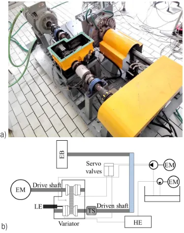
b)
Fig. 5. Chain CVT test bench; a) general view, and b) schematic layout
The chain CVT test bench is illustrated in Fig. 5, where EM, EB, HE, LE, and TS represent electrical motor, electromagnetic brake, heat exchanger, linear encoder and torque sensor, respectively. As shown in Fig. 5, a three-phase asynchronous four-pole, 30 kW Siemens motor is located to ensure the input power of CVT. The angular velocity of the motor is controlled by a Berges inverter. To provide the resistant torque, an electromagnetic brake connected to the output pulley of CVT by a belt transmission is used. The pressure, torque and displacement sensors are located on the input and output pulley shafts.
The characteristic data of the chain used for experiments are as follows: chain length
L = 649.49 mm, chain width b = 24 mm, the distance of the input and output pulleys’ centres d = 155 mm, the sheave angle β0 = 11 deg. The areas of the input and secondary pulleys are ADR = 0.01979 m²,
ADN = 0.009719 m² respectively.
The clamping force of drive side is calculated as follows:
SDR =P ADR DR+ωDR c DRf
2
, , (19)
where the coefficient fc,DR is:
fc DR, =π( oil)(rDR −rDR ), ρ
4 1
4 2 4
(20)
where ρoil = 870 kg/m³ at 20 ⁰C and rDR1 = 0.0825m and rDR2 = 0.0225 m. The driven clamping force is calculated as follows:
SDN =P ADN DN+ωDN c DN2 f , +Fspring, (21) where Fspring is the spring force on the driven pulley
and the coefficient fc,DN is:
fc DN, =π( oil)( r rDN DN −rDN −rDN ), ρ
4 2 1
2 3 2
2 4
3
4 (22)
where the quantities rDN1 = 0.06 m, rDN2 = 0.0225 m and rDN3 = 0.0321m.
The spring force is calculated using the following equation:
Fspring =FS0+2k rs(DN low, −rDN) tan(β0), (23) where FS0 = 536 N, the stiffness of the spring
ks = 20 N/m, the pitch radius of the driven pulley at
minimum speed ratio rDN,low = 0.0741 m.
RDR of the drive pulley is calculated with to following equation:
L=2dcosφ+R1α1+R2α2. (24) The following equation is used to calculate the
RDN:
RDN =RDN,max− a
tan ,
2 β0
(25)
where the RDN,max = 0.0741m.
Fig. 6. Representation of the measurement of the axial position of a moveable input pulley by a linear encoder
A control program is developed to perform the measurements and save all data in real time in a Labview environment. The measured data are the speed ratio, the pressures of the input and output pulleys, the resistant torque and the angular velocity. In the experiments, firstly, the angular velocity of the driven pulley is fixed, and then a torque load is implemented. After that, the pressure of the drive side is controlled and so the desired speed ratio is obtained due to the PI controller. In order to investigate the transient dynamics of CVT, a step of the set point of the speed ratio is implemented.
4 RESULTS AND DISCUSSION
In this section, the theoretical and experimental results and their comparison are demonstrated. First, the steady state results of the clamping forces ratios are given in Fig. 7 for the speed ratio equal to 1. It can be seen from this figure that the theoretical model is valid in steady state conditions, since it has a very good match with experimental results. Similar good matches are obtained for different speed ratios, which are not presented here. These steady state data are recorded to be used as a lookup table during the simulation.
The developed model for the speed ratio control is verified using several experiments for the different
initial conditions of the speed ratio, as indicated in Fig. 8.
Fig. 7. Theoretical and experimental results of the clamping force ratio as a function of traction coefficient at SDN = 10 kN and τ = 1
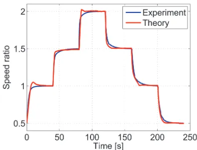
For the further comparison, the maximum and minimum speed ratios are implemented as an initial condition of the experiments and simulations shown in Fig. 9. It is observed from all these figures that the theoretical and experimental results are in good agreement. Thus, the developed model is verified, and it can be used in different controllers in automotive applications.
Fig. 8. Theoretical and experimental results of the transient response of the speed ratio for different initial condition of speed ratio at Kp = 1, Ti = 0.1, ωdr = 500 rpm, TDR = 50 Nm and
SDN = 20 kN
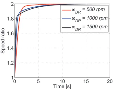
Since the CVT has a non-linear dynamic characteristic, the shifting response will be different for the different conditions especially for the different input speeds. In other words, the input angular speed is the most dominant term that affects the shifting speed linearly. Thus, the PI coefficients handled in Figs. 8 and 9 need to be tuned for the different angular velocities.
Fig. 9. Theoretical and experimental results of the transient response of the speed ratio for testing maximum and minimum range of speed ratio at Kp = 1, Ti = 0.1, ωDR = 500 rpm, TDR = 50
Nm and SDN = 20 kN
Fig. 10. Time response of the speed ratio for different angular velocity at Kp = 1, Ti = 0.3, TDR = 50 Nm and SDN = 20 kN
Fig. 10 indicates the time responses of the speed ratios for the different angular velocities of the input pulley with the same PI coefficients. This figure is evidence that PI gains of the speed ratio controller of the chain CVT have to be set for the different angular velocities.
To ensure the regular shifting response such as the same slope of the time response, the gains are scheduled by numerical experiments for different input speeds. First, the Ti is kept constant and Kp
is changed, and the settling time of speed ratio is obtained in case of no over-jumping conditions. The same procedure is followed for different integral time gains. The obtained data are recorded in a matrix considering the settling time of the speed ratio in case of the absence of over-jumping conditions. Fig. 11 indicates the settling times of the speed ratios for three different input angular velocities.
In Fig. 11, the minimum points of the surfaces show the best PI coefficients in terms of the settling time with no over jump. In this manner, a PI gains schedule is obtained as given in Table 1. That the difference between the desired and instant speed ratios be less than 0.001 is used as the criterion to determine the settling time seen in Fig. 11.
Fig. 11. Settling time of the speed ratio for the different input angular velocities
Table 1. PI Gains for different initial angular speed of the CVT
Input angular velocity (ωDR) Kp Ti
500 rpm 4.3 2.2
750 rpm 3.25 2.35
1000 rpm 2.5 2.35
1250 rpm 2.075 2.35
1500 rpm 1.75 2.35
1750 rpm 1.575 2.35
2000 rpm 1.35 2.35
Fig. 12. The transient response of the speed ratio for the different input speed with the PI coefficients given in Table 1
(TDR = 50 Nm and SDN = 20 kN)
The theoretical and experimental results show that the control-oriented modelling proposed in this paper is highly accurate, thus; this simplified formula can be used for different control design as a tool with specified lookup tables.
5 CONCLUSIONS
In this study, the shifting dynamics of the chain CVT is investigated to verify the theoretical model in a control application. A speed ratio controller is designed to provide a relative simple and easy-to-implement formulation as a look-up table and various experiments are performed to validate this model. The theoretical and experimental results indicate that the control-oriented modelling of transient dynamics of the variator is highly accurate. The verified model is used to obtain appropriate PI gains for having regular shifting speeds of the CVT under the different angular velocities via numerical experiments. Finally, a gain schedule is proposed for possible input speeds. These results are vital for engineers to design different control algorithms in automotive applications.
6 ACKNOWLEDGEMENTS
Ahmet YILDIZ would like to thank the TUBITAK for the scholarship granted. Special thanks are due to Prof. Dr. Giuseppe Carbone for suggestions and allowance the first author to perform the experiments in the test bench in Polytechnic of Bari, Italy.
7 REFERENCES
[1] Brace, C., Deacon, M., Vaughan, N.D., Horrocks R.W., Burrows C.R. (1999). The compromise in reducing exhaust emissions
and fuel consumption from a diesel CVT Powertrain over typical usage cycles. Proceedings of CVT Congress, Eindhoven, p. 27-33.
[2] Bottiglione, F., De Pinto, S., Mantriota, G., Sorniotti, A. (2014). Energy consumption of a battery electric vehicle with infinitely variable transmission. Energies, vol. 7, no. 12, p. 8317-8337,
DOI:10.3390/en7128317.
[3] Bottiglione, F., Contursi, T., Gentile, A., Mantriota, G. (2014). The fuel economy of hybrid buses: the role of ancillaries in real urban driving. Energies, vol. 7, no. 7, p. 4202-4220,
DOI:10.3390/en7074202.
[4] Mangialardi L., Mantriota G. (1996). Dynamic behavior of wind power systems equipped with automatically regulated continuously variable transmission. Renewable Energy, vol. 7, no 2, p. 185-203, DOI:10.1016/0960-1481(95)00125-5.
[5] Yildiz, A., Kopmaz, O. (2015). Dynamic analysis of a mechanical press equipped with a half-toroidal continuously variable transmission. International Journal of Materials and Product Technology, vol. 50, no. 1. p. 22-36, DOI:10.1504/ IJMPT.2015.066864.
[6] Yildiz, A., Kopmaz, O., Telli, C.S. (2015). Dynamic modeling and analysis of a four-bar mechanism coupled with a CVT for obtaining variable input speeds. Journal of Mechanical Science and Technology, vol. 29, no. 3, p. 1001–1006,
DOI:10.1007/s12206-015-0214-y.
[7] Carbone, G., Mangialardi, L., Mantriota, G. (2001). Theoretical model of metal V-Belt drives during rapid ratio changing.
Journal of Mechanical Design, vol. 123, no. 1, p. 111-117,
DOI:10.1115/1.1345521.
[8] Yildiz, A., Piccininni, A., Bottiglione, F., Carbone, G. (2016). Modeling chain continuously variable transmission for direct implementation in transmission control. Mechanism and Machine Theory, vol. 105, p. 428-440, DOI:10.1016/j. mechmachtheory.2016.07.015.
[9] Carbone, G., Mangialardi, L., Mantriota, G. (2005). The influence of pulley deformations on the shifting mechanisms of MVB-CVT. ASME Journal of Mechanical Design, vol. 127, no. 1, p. 103-113, DOI:10.1115/1.1825443.
[10] Carbone, G., Mangialardi, L., Bonsen, B., Tursi, C., Veenhuizen, P.A. (2007). CVT dynamics: theory and experiments.
Mechanism and Machine Theory, vol. 42, no. 4, p. 409-428,
DOI:10.1016/j.mechmachtheory.2006.04.012.
[11] Bonsen, B., Klaassen, T.W.G.L., Pulles, R.J., Simons, S.W.H., Steinbuch, M., Veenhuizen, P.A. (2005). Performance optimization of the push-belt CVT by variator slip control.
International Journal of Vehicle Design, vol. 39, no. 3, p. 232-256, DOI:10.1504/IJVD.2005.008473.
[12] Besançon-Voda, A. (1998). Iterative auto-calibration of digital controllers: methodology and applications. Control Engineering Practice, vol. 6, no. 3, p. 345-358, DOI:10.1016/ S0967-0661(98)00005-7.
[13] Jin, B.Q., Liu, Q. (2014). IMC-PID design based on model matching approach and closed-loop shaping. ISA Transactions,
vol. 53, no. 2, p. 462-473, DOI:10.1016/j.isatra.2013.11.005.
[15] Carbone, G., De Novellis, L., Commissaris, G., Steinbuch, M. (2010). An enhanced CMM model for the prediction of steady state performance in CVT chain drives. ASME Journal of Mechanical Design, vol. 132, no. 2, p. 1-8,
DOI:10.1115/1.4000833.
[16] Kong, L., Parker, R.G. (2008). Steady mechanics of layered, multi-band belt drives used in continuously variable transmissions (CVT). Mechanism and Machine Theory, vol. 43, no. 1, p. 171-185, DOI:10.1016/j. mechmachtheory.2007.02.003.
[17] Tenberge, P. (2004). Efficiency of chain-CVTs at constant and variable ratio: A new mathematical model for a very fast
calculation of chain forces, clamping forces, clamping ratio, slip and efficiency. International Continuously Variable and Hybrid Transmission Congress, paper no. 04CVT-35, UC Davis.
[18] Ide, T., Uchiyama, H., Kataoka, R. (1999). Experimental investigation on shift speed characteristics of a metal V-belt CVT. JSAE paper no.96363.