Function and Functionality in the Conceptual Design Process
Žiga Zadnik1,* - Mirko Karakaši2 - Milan Kljajin2 - Jože Duhovnik1
1
University of Ljubljana, Faculty of Mechanical Engineering, Slovenia
2
University of Osijek, Mechanical Engineering Faculty, Croatia
In order to contribute to functional modeling of product based on the functional synthesis paradigm, the work sets out to present criteria for the product functions and functionalities' definition. The product function matrix and their requests model has been generated that interrelates functions and technical systems. Functions are described in terms of parameters defined from physical laws. Through winning parameters correlation elements in the product function matrix and their requests are defined that interrelate functions and the technical systems which solve them. Winning parameters are derived from a set of parameters for each function thus they are of major importance and have the strongest impact on a given function. By the application of the product function matrix and their requests in the conceptual design process the designer can reexamine his or her work through comparison of the possibilities of realization of new ideas based on previously made products.
© 2009 Journal of Mechanical Engineering. All rights reserved.
Keywords: conceptual design, functional modeling, functional matrix, functionality matrix
0 INTRODUCTION
In a product development process, conceptual design is one of the most important phases in which customer needs and technical requirements are translated into design solutions. Customer needs play an important part in increasing the competitiveness of products in the product development process [1] and [2]. Conceptual design is a component part of a design process during which designers first create new ideas and then translate them into a design structure by synthesis. In the design process all products, that represent technical systems, exist for some reason and some purpose, i.e. they have some function. Functional modeling enables abstraction, direction, understanding and presentation of the overall product function [3]. Through a decomposition procedure the product overall function is decomposed into partial functions, necessary for the overall function to be performed. In this way the functional structure of product is built. It defines function as the conversion of energy, materials and information [4].
In order to achieve standardization of terminology in functional modeling there is a need for a standard dictionary called the basics of functions. Kirschman and Fadel [5] propose the taxonomy of basic mechanical functions. They suggest four elementary mechanical groups of
functions as a core of functional modeling. Works [3] and [6] to [7] divide functions and flows into classes to avoid ambiguity in defining the terminology connected with the terms used for functions and flows. In works [8] to [10] Žavbi describes functions setting up a chain of physical laws.
One of the main aims of the previously mentioned synthesis, based on the functional synthesis paradigm, is the generation of the structure of new technical systems by interrelating functional models and existing technical systems through which they can be realized [11]. Authors in [12] create a technical systems structure by correlating basic schematics, using geometric quantities through which simple technical systems, represented by basic schematics, receive input and send output quantities of energy, materials and information to their environment. Such quantities form places through which a technical system is connected with other technical systems in its environment.
Zadnik, Ž. - Karakaši, M. - Kljajin, M. - Duhovnik. J. 456
development of algorithms that are at the background of computer tools used as aids in the concept generation phase [18]. To automate the functional synthesis procedure i.e. design process, computational synthesis is being developed aimed at creating computer tools that back up the conceptual phase of design. Sridharan and Campbell are developing a computer tool based on functional modeling using graph-grammars [19].
Functional synthesis uses numerous tools for correlating functions and components and functions and physical laws. Very often matrix methods are used, like the morphological matrix, [20] and [21], construction matrix [22] and the house of quality [23].
The morphological method, based on the morphological matrix, was developed by Zwicky [24]. The morphological matrix as a tool is the result of decomposing the product overall function into partial functions that are then listed in the matrix. The matrix thus makes possible the identification of technical systems that solve functions in the matrix.
This work aims to contribute to functional modeling, by presenting criteria for determining product function and functionality. The criteria are upgraded and expanded compared with the criteria shown in [25]. The criteria thus defined are used in the model of product function matrix and their requests presented in the paper. The model is developed based on the model shown in [25]. The previous model is accepted and expanded with two structural forms of the product function matrix and their requests, generating the product matrix structure. Functions and functional systems that solve them are correlated in the model.
As they are not ambiguous, the matrix functions are described by parameters. Physical laws form the basis for the definition of parameters. Parameters include: basic physical quantities, derived physical quantities, geometric quantities and physical constants. The parameters that impact function most form winning parameters. Interrelations between functions and technical systems that solve them are performed through winning parameters. The matrix structure is built through common binding functions realized by those technical systems that are set in other matrices of product function and their requests. Thus, by correlating matrices, the
overall functional and design structure of a product is generated. Based on the listed functional structure of the previously made products, through product function matrix and their requests, there is a possibility to build the functional and design structure of new products as variants of previously made products. The work presents the first structural form of the product function matrix and their requests, which builds the lowest level of the listed product matrix structure.
The model has been implemented in a developed prototype computer system which helps the designer to generate the functional and design structure of both existing and new products as variants of previous ones based on functional synthesis through the function and functionality matrix.
1 PRODUCT, FUNCTION AND FUNCTIONALITY DETERMINATION
CRITERIA
As a starting point for the definition of criteria on how to list functions and functionalities of products the model developed in [25] was used. The model was accepted, expanded and upgraded by new criteria. The criteria were made based on the new knowledge acquired by the analysis of mass produced items. The notions obtained determine the product, its function and functionality in detail. The expanded model is shown in the text that follows.
1.1 Product Determination Criteria
Fig. 1. Product determination criteria
In the text that follows the criteria are described in more detail. By analogy, numbers of criteria in (Figure 1) correspond to the numbers given in the text:
1. Examples of products: automobile, computer, mobile phone, etc. Each of these products performs several functions. Automobile performs the function of transport from one to another place. Besides, it performs a number of other functions like: safety, comfort, ergonomy, etc.
2. Products are structured into eight levels from the simple to more complex ones: element, part, system, sub-assembly, assembly, machine, device and object. In Figure 2 the levels of products are shown. It is very important to note the context in which the product is being studied by levels. Thus, for example, in a given context an assembly can be a sub-assembly and vice- versa. Simplicity and complexity are to be considered from the aspect of functional and design structure. If the functional structure is more complex the design structure of the product is more complex too. Design structure results from functional structure of a product. Design models form design structure.
3. The word system, mentioned here, does not refer to the system level as defined in the second criterion but to the products that
compose the system in the following way: the system can be built from the top, an object is selected as a product to start the first level with. Then it descends to the second level which is the device. After that comes the third level with the machine, and the system's building ends with the fourth level, the assembly. The system does not necessarily start with object but with any of the levels of products shown in Figure 2. The system can be built from bottom to top too (Figure 2).
Zadnik, Ž. - Karakaši, M. - Kljajin, M. - Duhovnik. J. 458
4. The relationship between function and functionality and the functionality itself will be explained later in the text.
5. Criteria 6 and 7 explain this criterion in detail.
6. The technical model forms the technical design. Geometric features of the technical model include bore depth, rounding radius, admission depth, chamfer, etc.
7. The design model consists of building elements and components. It does not contain details like tooth flank curvature, specific geometrical features, but is characterized by the names of physical components. Its complexity can vary depending on the technical system complexity.
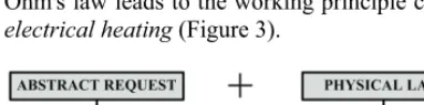
8. Working principle is presented as a description with words, by a schema or by the correlation of the function abstract form with physical or chemical law. For example, if the name of the given function is heating, then we can use Ohm's law as a physical law to describe this function. Correlation of this function with Ohm's law leads to the working principle called electrical heating (Figure 3).
Fig. 3. Transformation of abstract function to working principle
9. If the product has more than one function the procedure of the product decomposition is used, decomposing the product overall function to partial functions.
10. The main feature of modularity is the variation of loading or the change of intervals of the parameters that describe each function. With the modularity referring to shape, the number of functions that a particular product variant performs, must be found. If a certain variant contains all functions of some other variant in addition to the functions that the other variant does not have then this variant replaces the other one.
11. Modularity based on functions allows that different technical systems are used for the same functions. Modularity with regard to
function brings into relationship those products only whose main functions are the same. In addition to their main function products also have supplementary, auxiliary and binding function, the designer has to decide whether such a product has to be replaced by another product containing the same main function or left to perform its supplementary, auxiliary or binding functions.
1.2 Product Function
Product function implies the description of any technical system with regard to its work, process or physical characteristics. As a rule, it is described by words or sentences. When naming functions long and meaningless words are to be avoided and short and general terms chosen. Advantage should be given to verbs and adjectives. Nouns do not list a function but partly define it as technical system i.e. they are used as an aid for understanding some demanding function (for example, small displacements, high stress, control, driving, screw tightening, etc.)
One should be careful when there is a noun in the name of a function as it can reduce the level of abstraction, leading to solutions by which the desired function could be solved. In this way the designer departs from what is universally valid and essential and confines himself to what is material and concrete. This refers to the nouns that define the product name. For instance, a bearing has an additional function called sealing. Were the noun gasket in the name of the function, our function would be called sealing with gasket. The name of the function defined like this is not correct because it only gives one of the solutions for the function sealing.
function is also the overall function. Supplementary, auxiliary and binding functions are partial functions necessary for the main function to be performed.
A function is determined in accordance with the goal and usage of the technical system. Functions are described by physical expressions used in physical laws or if necessary completed by geometrical or topological relations. Physical expressions, geometrical and topological relations thus form parameters by which the function is unambiguously determined.
Fig. 4. Overall function of a technical system Depending on the complexity of function some functions sometimes need to be described with more physical expressions and parameters that are in these expressions. Table 1 shows functions described by parameters determined from physical expressions.
The function of a product can be easily determined with known technical systems performing a given technical process. When the technical system is not known and there is only a technical process or the technical process is unknown, instead of the list of functions there is a list of functional requirements. Functional
requirements are listed requirements that any technical process must perform in terms of work, process and physical characteristics. The technical process replaces natural process or translates it completely into a technical system.
1.2.1 Determination of the Function Type
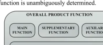
Product overall function can be divided into main, supplementary, auxiliary and binding function (Figure 4). Each one is explained in detail in the following text:
x Main function is a particularly prominent function of a product which defines the goal of the development-design process. This is the customer's most important requirement and the reason why it is taken into consideration when defining the goal. A product cannot be without a main function and can only have one main function. Table 2 shows examples of products and the main functions that they perform.
x Supplementary function is a supporting function required by the customer. It is important both in increasing the product complexity and defining new functions within the product's complex structure. A supplementary function is not indispensable for the main function performance. A product need not have or can have one or more supplementary functions.
Table 3 gives examples of products with their supplementary functions.
Table 1. Function description in terms of parameters
Name of function Parameters Physical expression Product
1. Sound absorption A
, , ,
D S PAPS, ,
P PI REF A D S; APS I REFI I
P P P
P P
D Noise
Absorber
2. Electric flow
conduction I,U,R,U,A,l
U I
R;
l R
A
U
Wire
Table 2. Examples of main functions performed by particular products
Product Main function
1. Bearing Rotation on one axis
2. Rotor plates
package
Direction of magnetic flux
3. Collector
Maintenance of magnetic field relative to referent field
Table 3. Examples of supplementary functions some products perform
Product Supplementary function
1. Bearing Sealing
Magnetic flux conduction
2.
Rotor plates package
Reduction of resistance to magnetic field
Zadnik, Ž. - Karakaši, M. - Kljajin, M. - Duhovnik. J. 460
xAn auxiliary function is determined by the work principle particularity and the product performance itself. A product need not have or can have one or more auxiliary functions. Table 4 gives examples of products and their auxiliary functions.
Table 4. Examples of auxiliary functions some products perform
Product Auxiliary function
1. Bearing Formation of vibrations
2. Rotor plate
package Heat release
3. Collector Rotation
xThe binding function enables interconnection between design and technical models thus helping in the performance of the necessary function. A physical connection is mechanically and physically based. The connection need not always be only physical. It can be realized through the flow of energy, material or signals performed on mechanical or physical bases. In an electric motor, in the rotor and stator interconnection, apart from the physical connection there is also an energy connection through a magnetic field, described by magnetic flow as a physical quantity. The physical quantity thus described is one of the parameters by which the binding function between these two elements is described.
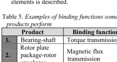
Table 5. Examples of binding functionssome products perform
Product Binding function
1. Bearing-shaft Torque transmission
2.
Rotor plate package-rotor envelopes
Magnetic flux transmission
3. Collector-
brushes
Electric flow conduction
4. Gear-shaft Torque transmission A product can have one or more binding functions. By means of the multi-level structured product function matrix and their requests, the binding function can be defined upwards, downwards or as a binding function at the same level. The building elements that are within the same product function matrix and
their requests and are interrelated are connected with each other by binding functions defined at the same level. According to Hubka and Eder [26] technical artifacts should be considered as systems connected with environment through input and output. Therefore it is impossible for the product not to have binding functions. In (Table 5) examples are given of interrelated products and their binding functions.
1.3 Function Determination Criteria
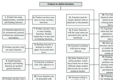
To avoid ambiguity and determine functions, criteria are defined for the determination of functions in order to achieve standardization in the conceptual design phase by functional modeling (Figure 5). The idea is to give the designer clearly defined rules on how and in which way to list the product functions.
In the text that follows criteria are explained in detail. Numbers of criteria (Figure 5) correspond to the numbers given in the text: 1. Each product has several functions and they
need to be defined precisely. For example a bearing is a product with the following functions: main – rotation about one axis, supplementary – sealing, auxiliary – vibrations, binding – torque transmission 2. One of the functions of the reduction gear
housing cover is sealing. By describing what is not necessary i.e. the function of the same name as sealing to prevent leakage of gas out of housing, will only add to the misunderstanding of the function itself. 3. If a product has several functions the main
function is to be defined. Other functions can be supplementary, auxiliary and binding, needed for the performance of the main function. 4. These functions are necessary for the main
function of the product to be performed. 5. The product shown in (Table 3) is a packet
of rotor plates, the rotor having two supplementary functions.
6. In (Table 4) products with auxiliary functions are shown.
7. This criterion was explained in the previous section.
8. This criterion was explained in the Function of products section.
Table 6. Assignment of usage interval for prestressed force
Element Function Parameter Interval
Fp- prestressed force, kN 1 to 10 pr- prestressing N/mm2 250
1. Screw Prestressed screw connection
Aj- screw core section, mm2 80
Table 7. Products with similar functions
Product Function Parameters Interval values Winning
parameters
/ Min Max
I- current intensity, A 50 50
U- voltage, V 230 230
1. Graphite
insert
Electric flow conduction
R- conductor resistance, 4.6 4.6
U, R
/ Min Max
I- current intensity, A 50 50
U- voltage, V 230 230
2. Graphite
insert wire
Electric flow conduction
R- conductor resistance, 6.5 6.5
U, R
10. Description of the function through parameters is shown in (Table 1).
11. Criterion 11 is expanded and explained in criterion 12.
12. For example fixing 1, fixing 2, fixing 3, ..., fixing i; i = 1,...,n. Each of these functions
is different in the description of parameters and their interval values, therefore they are not the same and similar functions.
13. Intervals of usage are assigned to parameters. An example for a screw is given in (Table 6).
Zadnik, Ž. - Karakaši, M. - Kljajin, M. - Duhovnik. J. 462
14. For example the function named heating is realized by different design models and technical designs: electric heater, hair dryer, air-conditioner, etc.
15. Technical model is a product that solves the assigned function.
16. Understanding criterion 17 will make criterion 16 easier to understand.
17. Similar functions have the same names. Two products having similar main functions are shown in (Table 7). If only one maximum value of the parameter is defined then it is considered as a minimum and maximum value within the interval value. 18. The saturation of the technical system is
then checked by the application of modularity with reference to function. For example, graphite sail guide and graphite sail in electric motor rotor have similar main functions named electric flow conduction. It is necessary to check the technical system saturation with reference to its main functions and see if both technical systems could be replaced by one technical system.
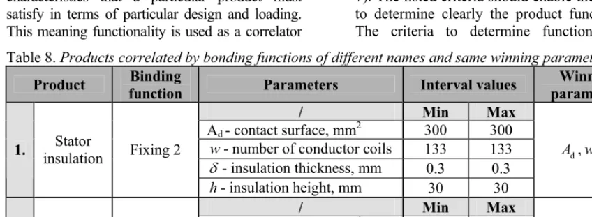
19. Table 8 shows two products correlated by binding functions of different names but with same winning parameters.
20. Tables 7 and 8 show the winning parameters of the listed technical systems defined functions.
1.4 Product Functionality
Functionality is defined as the specific characteristics that a particular product must satisfy in terms of particular design and loading. This meaning functionality is used as a correlator
between the function and the design of a product (Figure 6). Technical design or make of a product depends on its functionality. Designing process begins by first considering functional requirements and desires that are either described or schematically presented. Functions or functionalities are presented as described requirements. Design models or known technical systems are presented as schematic requirements.
Table 9 illustrates an example of functionality where prestressed force represents the parameter defined by the value of the interval that describes the function named prestressed screw connection. The 5 kN value of the prestressed force determines the functionality of the function prestressed screw connection, the functionality resulting from the interval value of the parameter that describes the function. Therefore, functionality can be understood as an exactly determined solution of the thus defined simple function.
Table 9. Product function and functionality
Product function Product functionality
Prestressed screw connection in range
1 to 10 kN
Prestressed force value of 5 kN
1.5 Functionality Determination Criteria
To understand completely the way the function and functionality are correlated and the way the functionality is determined from the product function, a list is made of criteria that determine the functionality of a product (Figure 7). The listed criteria should enable the designer to determine clearly the product functionality. The criteria to determine functionality are Table 8. Products correlated by bonding functions of different names and same winning parameters
Product Binding
function Parameters Interval values
Winning parameters
/ Min Max
Ad - contact surface, mm2 300 300
w- number of conductor coils 133 133
G - insulation thickness, mm 0.3 0.3
1. Stator
insulation Fixing 2
h- insulation height, mm 30 30
d
A ,w,
h
/ Min Max
Ad - contact surface, mm2 300 300
w- number of conductor coils 133 133
l- conductor length, mm 4000 6000
2. Stator
envelopes Fixing 3
h- insulation height, mm 30 30
d
Fig. 6. Correlation between function and technical design [27]
Fig. 7. Product functionality determination criteria
explained in detail in the text that follows. By analogy, the numbers of the criteria in (Figure 7) correspond to the numbers shown in the text.
1. Main functionality results from main function, supplementary functionality from supplementary function, auxiliary functionality from auxiliary function and binding functionality from binding function.
2. In the real world a product is functionality by itself. It is described by one or more functions and as such solves at least one function or more functions.
3. As there is no product without a function there can be no product without functionality.
4. The interval within the interval of the parameter by which the given function is described gives a narrower interval of usage. If the speed interval value at an automobile speed counter is determined to be from 0 to 220 km/h, then the narrower interval of usage is the really possible maximally achieved speed determined by the interval from 0 to 185 km/h.
Zadnik, Ž. - Karakaši, M. - Kljajin, M. - Duhovnik. J. 464
6. The technical model is determined by the technological process and has geometric features. The design model does not have the details of the technical model and represents the objectivization or the work principle model.
7. If one product performs multiple functions then its main function can be decomposed to several partial functions.
8. The criterion is closely connected with criterion 9 when determining the product.
9. If no supplementary function is found for two functionally identical products, only one product is to be selected. Otherwise, saturation of the technical system could occur.
2 PRODUCT FUNCTION MATRIX AND THEIR REQUESTS MODEL
The product function matrix and their requests is developed as a tool to aid the designer in the conceptual design phase to generate new variants of a product on the basis of previously made products. Functions and the technical systems that solve them are correlated within the matrix. The purpose of the product function matrix and their requests is not only to give direction for defining requirements but also to establish new requirements continuously. The model of product function matrix and their requests was made by expanding the model of function and functionality matrix described in [25].
The starting point in defining the product function matrix and their requests is the product functional structure which forms the input into the product function matrix and their requests. Thus the products at different levels must first be connected into a system. After the system has been established, listing of the system is made by means of functions.
Within the system, levels are marked with numbers from the set of natural numbers, except for the number zero which is not used for numbering the levels. Thus, the top level is marked as number one so that it becomes the first level. Each of the next levels is marked with the next natural number till the last level is reached. In making the list of functional structure, not all of the levels are analogous to the levels of the design structure. If the design structure consists of four levels then the functional structure consists of three levels, i.e.
always one level less. This results from the fact that on the last level of functional structure, partial functions that solve the main functions on that level, are put on the list. Partial functions are the main functions of simple technical systems that are on the last level of design structure and are indexed in the data base of the developed computer tool. It can be concluded that the functional structure levels of the product being listed are analogous to the design structure levels up to the design structure penultimate level where the levels of functional structure end. The levels of the product function matrices and their requests in the matrix structure correspond by analogy to the functional structure levels of the listed product. Thus the functions and the product function matrices and their requests are listed by levels.
If the system structure is such that its last two levels are part and element, then in the design structure they are “conditionally” merged together into one level. Conditionally, because part and element are simple technical systems that are indexed in the data base and as such, in the rough functional structure they are represented by partial functions in the last level of functional structure. The other reason is that part has a design structure composed of elements of the same kind, while it could also be that part does not even exist, so that elements are directly connected into the system which is on a higher level.
The product function matrix and their requests is built up from the bottom to the top level within the matrix structure, after a detailed functional structure of the product has been determined. This is why the matrix has two structural forms. The first structural form refers to the functions and the technical systems that solve them, and they are on the lowest (last) level of the listed system. The other, higher-level structural form refers to all other higher-levels that are above the lowest level of the indexed system.
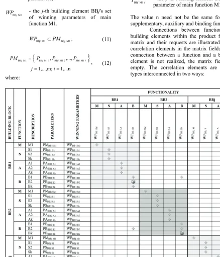
2.1 First Structural Form of Product Function Matrix and Their Requests
described system matrix structure is illustrated in Figure 8. Within the product function matrix and their requests the functions are classified by types of functions in the column named function in the following way: main function, designated by (M) in the matrix, supplementary function, designated by (S) in the matrix, auxiliary function, designated by (A) in the matrix and binding function, designated by (B) in the matrix.
Functionalities are represented through building elements that solve the defined functions. Building elements represent the technical systems, which form design models. Technical systems can be of different complexity. More complex technical systems are composed of less complex technical systems. Thus element and part, being less complex technical systems, correlate into more complex technical systems on higher levels of the function and functionality matrix. At least one building element can be in the matrix.
Aiming at the simplicity of the model, the names of building elements are designated by common marks: BB1, BB2,…, BBj:
1,...,m
j (Figure 8). These marks are replaced by the real names of building elements in the prototype implementation of the model. The names of technical systems that solve particular functions are given in the column building element. The column is there to facilitate coping with the matrix.
The column description contains the names of functions. For the sake of model simplicity the names are given by common marks. The main function's name is marked by (M1). Each building element can have only one main function. In the prototype implementation of the model, real names are used for the main functions of building elements as well as for the names of supplementary, auxiliary and binding functions. The names of the matrix model supplementary functions are marked by: S1, S2,…, Sk: k 1,...,p. A building element can have one or more supplementary functions. A building element may have no supplementary function. Auxiliary functions are marked by: A1, A2,…, Ak: k 1,...,p. A building element can have one or more auxiliary functions. A building element may have no auxiliary function. Binding functions are marked by: B1,
B2,…, Bk; k 1,...,p. A building element cannot be without at least one binding function in its structure. The value 1 need not be the same for supplementary, auxiliary and binding function.
Owing to its being unambiguous each function is described by parameters. Depending on the function's complexity, the function can be described by varying number of parameters. There can be no function there is no parameter for if without a parameter it is not a function. The parameters for all defined functions are listed in the column parameters (Figure 8).
After all the parameters that unambiguously determine the functions have been listed, winning parameters should be chosen. Winning parameters are determined for each function separately, and they represent those parameters that have the strongest impact on a particular function. A function can have at least one winning parameter. Based on experience and on product properties the designer determines the winning parameters of a function. It is not possible for all the parameters that describe a particular function to be the winning parameters of the function at the same time. All the winning parameters for each defined function are listed in the winning parameters column (Figure 8). To facilitate the explanation of the product function matrix and their requests model, in columns parameters and winning parameters, the parameters and the winning parameters are represented using sets for each particular type of function. A particular building element can have several supplementary, auxiliary and binding functions. Therefore, a set of winning parameters is defined for each supplementary, auxiliary and binding function.
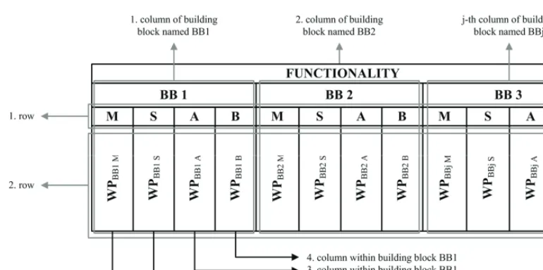
Below the row functionality there are columns with the names of building elements listed in the table. It is possible to include j = 1,..., m of building elements in the matrix where a j appears in the name of the building element.
Zadnik, Ž. - Karakaši, M. - Kljajin, M. - Duhovnik. J. 466
row contains winning parameters for the type of function that is in the first row determined by the corresponding column. In each column of the second row a new set is formed of all winning parameters for each particular type of function that contains the sets of winning parameters from the column winning parameters, for a particular building element.
In general, the j-th building element BBj can be mathematically presented in the following way:
x for supplementary functions:
^
`
BB S BB S1, BB S2,..., BB S
1,...,m; 1,...,p
j j j j k
WP WP WP WP
j k
, (1)
where: BB Sj
WP - set of all winning parameters of the j-th building element BBj 's all supplementary functions S,
BB Sj k
WP - the j-th building element BBj's set of winning parameters of the k-th supplementary function Sk.
BB Sj k BB Sj k
WP PS , (2)
^
`
BB S BB S 1, BB S 2,..., BB S
1,...,m; 1,...,p; 1,...n j k j k j k j k i
PS P P P
j k i
, (3)
where: BB Sj k
PS - the j-th building element BBj's set of parameters of the k-th supplementary function Sk,
BB Sj k i
P - the j-th building element BBj's i-th parameter of the supplementary function Sk.
x for auxiliary functions:
^
`
BB A BB A1, BB A2,..., BB A
1,...,m; 1,...,p
j j j j k
WP WP WP WP
j k
, (4)
where: BB Aj
WP - set of all winning parameters of the j-th building element BBj 's all auxiliary functions A,
BB Aj k
WP - the j-th building element BBj's set of winning parameters of the k-th
auxiliary function Ak.
BB Aj k BB Aj k
WP PA , (5)
^
`
BB A BB A 1, BB A 2,..., BB A
1,...,m; 1,...,p; 1,...n j k j k j k j k i
PA P P P
j k i
, (6)
where: BB Aj k
PA - the j-th building element BBj's set of parameters of the k-th auxiliary function Ak,
BB Aj k i
P - the j-th building element BBj's i-th parameter of the k-th auxiliary function Ak.
x for binding functions:
^
`
BB B BB B1, BB B2,..., BB B
1,...,m; 1,...,p
j j j j k
WP WP WP WP
j k
, (7)
where: BB Bj
WP - the j-th building element BBj's all binding functions B set of all winning parameters,
BB Bj k
WP - the j-th building element BBj's set of winning parameters of the k-th binding function Bk.
BB Bj k BB Bj k
WP WP , (8)
^
`
BB B BB B 1, BB B 2,..., BB B
1,...,m; 1,...,p; 1,...n j k j k j k j k i
PB P P P
j k i
, (9)
where: BB Bj k
PB - the j-th building element BBj's set of parameters of the k-th binding function Bk,
BB Bj k i
P - the j-th building element BBj's i-th parameter of the k-th binding function Bk.
x for main functions:
As each building element can have only one main function, the above expressions are to be adapted in the following way:
^
` ^
`
BB M BB M BB M1
1,...,m; 1
j j k j
WP WP WP
j k
where: BB Mj
WP - the j-th building element BBj's main function M set of all winning parameters,
BB M1j
WP - the j-th building element BBj's set of winning parameters of main function M1.
BB M1j BB M1j
WP PM , (11)
^
`
BB M1 BB M1 1, BB M1 2,..., BB M1
1,...,m; 1,...n
j j j j i
PM P P P
j i
, (12)
where:
BB M1j
PM - the j-th building element BBj's set of parameters of main function M1,
BB M1j i
P - the j-th building element BBj's i-th parameter of main function M1.
The value n need not be the same for main, supplementary, auxiliary and binding function.
Connections between functions and building elements within the product function matrix and their requests are illustrated by the correlation elements in the matrix fields. If the connection between a function and a building element is not realized, the matrix fields are empty. The correlation elements are of two types interconnected in two ways:
Zadnik, Ž. - Karakaši, M. - Kljajin, M. - Duhovnik. J. 468
Fig. 9. Illustration of the set of all winning parameters
- connection within the matrix,
- connection towards the matrices on the same level and the matrices on other levels.
Correlation within the matrix is performed between the main, supplementary, auxiliary and binding functions and the building elements that solve the given functions. When correlating main function and building element that solves it, the set of the main function winning parameters listed in the column winning parameters is to be equal to the set of all winning parameters for this type of function found in the second row and the first column of this building element (Figure 9). If this condition is not satisfied, connection between the main function and the building element cannot be realized. The j-th building element named BBj can be written as:
BB M1 BB M
1,...m
j j
WP WP
j (13)
As a building element can have one or more auxiliary functions, individual correlation is performed between each auxiliary function and the corresponding building element that solves each of these functions. Therefore, the set of the winning parameters for each particular auxiliary function from the column winning parameters is to be within the set of all the winning parameters for this type of function
found in the second row and the first column of this building element product function matrix and their requests (Figure 9). If this condition is not satisfied, connection between the auxiliary function and the building element cannot be realized. In the case where the building element does not solve any auxiliary function, the fields of the product function matrix and their requests are empty. The j-th building element named BBj can be written as:
BB A BB A
1,..,m; 1,...p j k j
WP WP
j k
(14)
The analogy with binding functions is the same as with supplementary and auxiliary functions. The condition for interconnecting the j-th building element named BBj and the binding function can be written as:
BB B BB B
1,..,m; 1,...p j k j
WP WP
j k
(15)
elements that fill those fields are the result of shared binding functions which have the same sets of winning parameters and building elements where these sets of winning parameters are sub-sets of their sets of all winning parameters, for the types of binding functions from the second row and first column of these building elements (Figure 9). Through these binding functions the building elements are correlated within the product function matrix and their requests.
Correlation with other matrices on the same level and the matrices on other levels is made through shared binding functions by those building elements that are within other function and functionality matrices. The sets of winning parameters of these binding functions are the sub-sets of the set of all winning parameters for the types of binding functions of these building elements. This type of correlation can only be found on main diagonals of the product function matrix and their requests.
In computer tool prototype implementation, these correlations present in detail the levels with matrices within which there are building elements interconnected by common binding functions, winning parameters characteristic of binding functions and the name of the common matrix in which the correlation between building elements has been performed.
The product function matrix and their requests is composed of its sub-matrices within which the functions grouped in four types are correlated with the building element that solves them (Figure 8). It can be seen from the figure that the sub-matrices are positioned in the direction of the product function matrix and their requests main diagonal.
3 CONCLUSION
The design process is determined as a correlation between the product function and its design. Once the design task is defined, the main function and functionality of the future product is determined. The design process starts with functional requirements and desires that can be either described through functions or functionalities, or presented graphically through design models and known technical systems. One of the most important phases of the design process is the conceptual phase in which the
customer requirements and engineering requirements are translated into design solutions. The conceptual design phase is an integral part of designing process during which designers create new ideas, transforming them into a design structure after that.
Functional modeling plays an important part in the conceptual and design process because it enables abstraction, direction, understanding and presentation of the product overall function. In a design process all products that present technical systems, are there for some purpose and some reason, i.e. they have their function.
The work presents the first structural form of the product function matrix and their requests. The matrix is used to determine the design process as a correlation between the product function and its technical form, defined in detail as functionality. Each product listed in the matrix represents a functionality that results from the product main, supplementary, auxiliary or binding function. The product functions are described in more detail by the parameters that present physical quantities, geometric values and physical constants. The list of parameters for particular functions in the form of a matrix is the innovation that the work provides. By determining winning parameters the correlation is made possible between the listed functions and technical systems that solve them. The winning parameters are most important and with strongest impact on the defined functions and are determined from the defined functions' set of parameters. A special emphasis should be given to the fact that intervals of numerical and descriptive values are also created in the list, i.e. the parameters are given real sense.
The product function matrix and their requests serves as a tool by which the designer generates functional and design structures of existing products in the conceptual design phase. It also makes it possible for the designer to build functional and design structures of new products as variants of existing products on the list in the product function matrix and their requests.
Zadnik, Ž. - Karakaši, M. - Kljajin, M. - Duhovnik. J. 470
because a sub-matrix appears in the matrix, the designer is shown whether he or she is on the right track. If the sub-matrix does not appear, either the system of functions is wrong or there is a surplus of functionalities of a particular technical system so that they are in some way unsuitable for usage. In the matrix itself rows of particular functions can be raised or lowered. This is permissible because the product development cannot be predetermined so that the position of rows is changed according to the state of development and knowledge of the problem itself. Thus the designer can know if he or she is on the right track in designing the new product. In this way the designer reexamines his or her idea, comparing it with the previous design solutions.
4 ACKNOWLEDGMENT
The work presented in this paper is financially supported by the Ministry of Higher Education, Science and Technology of the Republic of Slovenia and the Ministry of Science, Education and Sports of the Republic of Croatia through a bilateral project.
5 REFERENCES
[1] Kušar, J., Duhovnik, J., Tomaževi, R., Starbek, M. (2007) Finding and Evaluating Customers Needs in the Product-Development Process, Strojniški vestnik – Journal of Mechanical Engeneering, vol. 53, no. 2, p. 78-104. [2] Kušar, J., Bradeško, L., Duhovnik, J.,
Starbek, M. (2008) Project Management of Product Development, Strojniški vestnik vestnik – Journal of Mechanical Engeneering, vol.54, no. 9, p. 588-606. [3] Hirtz, J., Stone, R.B., McAdams, D.A.,
Szykman, S., Wood, K.L. (2002) A Functional Basis for Engineering Design: Reconciling and Evolving Previous Efforts. NIST Technical Note 1447, Department of Commerce United States of America, National Institute of Standards and Technology.
[4] Pahl, G., Beitz, W. (2001) Engineering Design: A Systematic Approach. Springer-Verlag, London, p. 29-30, ISBN 3-540-19917-9.
[5] Kirschman, C.F., Fadel, G.M. (1998) Classifying Functions for Mechanical Design. Journal of Mechanical Design vol. 120, no. 3, p. 475-482.
[6] McAdams, D.A., Stone, R.B., Wood, K.L. (1999) Functional Interdependence and Product Similarity Based on
Customer Needs. Research in
Engineering, vol. 11, no. 1, p. 1-19. [7] Stone, R.B., Wood, K.L., Crawford, R.H.
(2000) A heuristic method for identifying modules for product architectures. Design Studies, vol. 21, no. 1, p. 5-31. [8] Žavbi, R., Duhovnik, J. (2001)
Conceptual design chains with basic schematics based on an algorithm of
conceptual design. Journal of
Engineering Design, vol. 12, no. 2, p. 131-145.
[9] Žavbi, R., Duhovnik, J. (2000) Conceptual design of technical systems using functions and physical laws. Artificial Intelligence for Engineering Design, Analysis and Manufacturing, vol. 14, no. 1, p. 69-83.
[10] Žavbi, R., Duhovnik, J. (2000) The Problems of Transition from Basic Schematics to a Scematic of a Technical System. Proceedings of the 6th International Design Conference-Design 2000. Dubrovnik, May 23-26, p. 67-72. [11] Chakrabarti, A. (2004) A New Approach
to Structure Sharing. Journal of Computing and Information Science in Engineering, vol. 4, no. 11, p. 11-19. [12] Rihtarši, J., Žavbi, R., Duhovnik, J.
(2005) Part synthesis using physical laws and allocation of wirk elements. Engineering Design and the Global Economy. ICED 05. Melbourne, August 15-18, file No. 72.386.
[13] Kurtoglu, T. (2007) A Computational Approach to Innovative Conceptual Design. PhD thesis (in English), The University of Texas at Austin, Austin. [14] Ahrens, G. (2000) The Collection and
Management of Product Requirements./ PhD thesis (in German), Der Technischen Universität Berlin, Berlin. [15] Prudhomme, G., Zwolinski, P., Brissaud,
process the needs of those involved in the product life-cycle. Journal of Engineering Design, vol. 14, no. 3, p. 333-353.
[16] Kurtoglu, T., Campbell, M.I., Bryant, C.R., Stone, R.B., McAdams, D.A. (2005) Deriving a Component Basis for Computational Functional Synthesis. Engineering Design and the Global Economy. ICED 05. Melbourne, August 15-18, file No. 123.1.
[17] Bryant, C.R., Stone, R.B., McAdams, D.A, Kurtoglu, T., Campbell, M.I. (2005) Concept Generation from the Functional Basis of Design. Engineering Design and the Global Economy. ICED 05. Melbourne, August 15-18, file No. 222.1.
[18] Rude, G.H., Grein, S., Meis, G., El-Mejbri, E. (1998) Universal Design Theory: Elements and Applicability to Computers. Universal Design Theory-Proceedings of the Workshop Universal Design Theory. Shaker-Verlag, Aachen, p. 209-222.
[19] Sridharan, P., Campbell, M.I. (2005) A Study on the Grammatical Construction of Function Structure. Artificial Intelligence for Engineering Design, Analysis and Manufacturing, vol. 19, no. 3, p. 139-160.
[20] Huang, G.Q., Mak, K.L. (1999) Web-based morphological charts for concept design in collaborative product development. Journal of Intelligent
Manufacturing, vol. 10, no. 3/4, p. 267-278.
[21] Kljajin, M., Ivandi, Ž., Karakaši, M., Gali, Z. (2005) Conceptual Design in the Solid Fuel Oven Development. Proceedings the 4th DAAAM International Conference on Advanced Technologies for Developing Countries. Slavonski Brod, September 21-24, p. 109-114.
[22] Suh, N. (2001) Axiomatic design-advances and applications. Oxford University Press, Oxford, ISBN 0-19-513466-4.
[23] Hauser, J.R., Clausing, D. (1988) The house of quality. Harvard Business Review, p.63-73.
[24] Zwicky, F. (1948) The morphological method of analysis and construction. Courant anniversary volume. New York: Intersciences Publish, p. 461-470. [25] Duhovnik, J., Tavar, J. (2005) Product
Design Test using the Matrix of Functions and Functionality. Proceedings of AEDS 2005 Workshop. Pilsen, November 3-4, p. 950-963.
[26] Hubka, V., Eder, W.E. (1988) Theory of Technical Systems. Springer-Verlag Berlin, Heidelberg, ISBN 0-387-17451-6.

![Fig. 6. Correlation between function and technical design [27]](https://thumb-us.123doks.com/thumbv2/123dok_us/8953223.1862591/9.581.127.434.303.505/fig-correlation-function-technical-design.webp)