Loa
A
1-3
L
E Y
ℎ T W G S I I B
k V
A F L S E T T T 1.Assistan 2.Professo 3. MSc gra
ading
Aeroe
3. Departmen Th determ Eleme to sim quasi the a dynam exam shorte analy loads obtain KeywNom
Length Young’s modu Thickness Width Shear modulus In-plane defor In-plane defor Bending defor Vector of curv Axis perpendi Free stream ve Lift force Surface area External force TimeThe first varia The first varia
nt Professor (Co or
aduate
Estim
elastic
H. Shahv
nt of Aerospa Engi
The aim of thi mines the indu ent (FE) code b mulate the aer i-steady aerodyn
erodynamic loa mic response an ined and the eff ening terms in ysis of an insec including shea ned results sign
words: Aerodynam
menclature
ulus
s
rmation in x di rmation in y di rmation vatures
cular to the pl elocity
e
ation of strain ation of veloci
orresponding au
mation
c Effec
M
verdi
1, A. S.
ace Engineeri ineering, Am
Postal Code H_sh
is paper is to uced wing load based on a four oelastic behav namic model is ads. In order f nalyses of a ro ffect of dynamic the equations o ct-like wing und ar force and be nify the contribu
mic, Aeroelastic,
e
123 irection irection late energy ty component uthor)n of Fl
ct Usi
Metho
. Nobari
2a
ing and Cente irkabir Univ
e:15875-441 hahverdi@a
o provide an ds during flapp r-node plate be
ior of flapping s incorporated i for the validati tating flat plate c stiffness on th of motion, is al der a specified ending moment ution of wing st
Flapping wing, F
ts N N N
lappin
ing Fi
od
nd H. Bahr
er of Excellen ersity of Tec
13, Tehran, Ir aut.ac.ir
aeroelastic co ping flight. Fo ending element f g wings in low
into the aeroela ion of the pres e under pure fl he plate respons
lso investigated d motion is carr t at the wing ro tructural elastic
Finite element, Dy
The fir Virtua Veloci Positio Positio Positio
, , Inertia
, , Flappi
, , Pitchin N1 Shape N2 Shape N3 Shape Dynam Dynam Lift co Time t Eleme Eleme Eleme Eleme Eleme Eleme Eleme
ng Wi
inite E
rami Torab
nce in Compu chnology
ran
omputational to or this purpose
formulation is w incompressibl astic model for p sent tool, the m lapping motion
se, due to the p d. Finally, the a
ried out and th oot are determ city to the induc
ynamic stiffness
rst variation o al displacemen ity of a pint on on of an eleme on of a point on of a point a reference fra ing reference f ng reference f
function for i function for i function for b mic stiffening mic stiffening oefficient
to reach the st ental degrees o ental stiffness ental Velocity ental accelerat ental mass mat ental damping ental dynamic
ings u
Eleme
bi
3 utational Aero ool which e, a Finite developed le flow. A predicting modal and are firstly presence of aeroelastic he induced ined. The ced loads.of kinetic ener nt of the system
n the wing ent on the win on the wing in on the wing in ame frame frame in-plane defor in-plane defor bending defor in x direction in y direction
teady state of freedom ve
matrix vector tion vector trix matrix stiffness matr
under
ent
ospace rgy m ngn x direction n y direction
10
/
Journal of Aerospace Science and TechnologyVol. 11/ No. 1/ Winter-Spring 2017 H.Shahverdi,A.S.Nobariand H.BahramiTorabi
Elemental force vector Forward flight velocity
Velocity due to elastic deformations Position vector
Downwash
Normal vector perpendicular to the flow velocity
Vector of membrane strains mass density
Poisson’s ratio Stress
Pitching angle Flapping angle
Angular velocity of the wing Steady state angular velocity Flapping velocity
Pitching velocity Flapping acceleration Pitching acceleration Operator matrix Operator matrix
Deformation vector (u, v ,w )
∝ Effective angle of attack Rotational speed Elastic rotation angle Rigid rotation angle
Introduction
Nowadays, or nithopters are commonly used in both civil and military missions. The deep understanding of flapping mechanism in conjunction with aerodynamic pattern and aeroelastic behavior in these vehicles can lead to the improved design process of such air vehicles and their efficiency and performance. The basic idea of these vehicles has been taken from natural fliers, such as insects and birds. In these creatures, inertial and aerodynamic forces can enforce significant elastic deformation during flight. The interaction between aerodynamic, inertial and elastic forces results in a complex fluid-solid interaction (FSI) problem regarding this topic. Thus, to improve the design process and control of such vehicles, the exact determination of induced loads or trust in the presence of aeroelastic considerations is necessary. For this purpose, it is conventional to use numerical or experimental techniques. However, the experimental methods may face the problem in simultaneous measurement of wing deformations, aerodynamic force and wing kinematics. To overcome these difficulties, numerical methods or simulations are more
model of a Flapping Micro Air Vehicle (FMAV) based on the Euler-Bernoulli beam model and a proposed quasi-steady aerodynamic model. They showed the validity of their computational model in loading determination process via an experimental investigation [13]. Gordnier et al. created a numerical framework for the aeroelastic simulation of flexible flapping wings [14]. A higher order Navier-Stokes solver and a structural dynamic solver based on the geometrically nonlinear slender beam model were incorporated into their aeroelastic model. They showed good agreements between the numerical results and those achieved experimentally by Heathcoat et al. [15]. In a similar work, Lee et al. developed a computational aeroelastic tool to study the effect of elasticity on the vehicle performance of a FMAV. To reach this goal, a finite volume based preconditioned Navier-Stokes solver with a nonlinear structural model based on the geometrically exact beam model was used [16]. Dong et al. performed some numerical and experimental studies on the effect of structural damping on the deformation of a flexible flapping wing. The results indicated that the damping effect plays an important role during flapping [17]. Dewei et al. studied the effect of flexibility on the aerodynamic force in a flapping motion of a chord-wise flexible wing. They used the Lattice Boltzmann Flexible Particle Method (LBFPM) to simulate its aeroelastic behavior. They found that both the rotational and translational inertia that contribute to the deflection are limited by flexural rigidity [18]. As a result, all of the performed researches in this field rely on the induced loads due to a flapping mechanism under elastic effect.
The main objective of the present paper is to develop a computational tool for loading estimation of a flapping wing under aeroelastic effect. In this regard, the equations of motion of the wing are obtained using energy method. A finite element model based on the Bogner-Fox-Schmit (BFS) element is utilized to simulate the structural dynamics behavior of the wing as a rotating flat plate. Based on the aforementioned literature, a quasi-steady aerodynamic model instead of the complex ones is considered to decrease the computational efforts as a novelty of the present study. By incorporating this aerodynamic model into structural dynamic equations, the aeroelastic equations are produced. The validity of the developed tool is examined with the data available in literature.
Structural model
Since most birds in nature and the artificial flappers prototyped for experiment have low aspect ratio wings, a beam model is not suitable for predicting the realistic dynamic behavior of such wings. So, in order to obtain valid results, employing a plate model as the basis for structural dynamic simulation is necessary. Also, this structural element provides the chord-wise flexibility of a flapping wing during flight simulation. In the present study, the equations of motion of a rotating flat plate (Fig. 1) are determined by extended Hamilton’s principle [19].
2
1
0
t
t
T
U
W dt
(1)where T, U and W indicate kinetic energy, strain energy, and work done by non-conservative forces, respectively.
Figure 1. Schematic of a rotating flat plate
The strain energy of the wing is defined as
= (2)
It should be noted that in the present study, the classical plate theory (CPT) is used to achieve a numerical framework for the structural simulation of a flapping wing. Based on the small deformations assumption, the strain components for a flat plate are written as follows [20]:
= −
= −
= + − 2
(3)
12
/
Journal of Aerospace Science and TechnologyVol. 11/ No. 1/ Winter-Spring 2017 H.Shahverdi,A.S.Nobariand H.BahramiTorabi
= + (4)
where ϵ is vector of membrane strains,
denotes vector of curvatures and z is the
coordinate axis perpendicular to the mid plane of plate. By substituting the constitutive equation
( σ = Q ϵ ) along with the strain components
into Eq. 2, the first variation of the strain energy can be written as:
= ∬ ( + +
+ )
(5)
where A, B, and D are defined as:
=
=
=
(6)
The kinetic energy of the wing is obtained through the following equation
= 1
2 (7)
The first step for determining the above statement is to express the velocity vector of an arbitrary point in the mid-plane of the plate. Thus, the velocity vector of an assumed master
point l can be found using the following
equation,
= = + + (8)
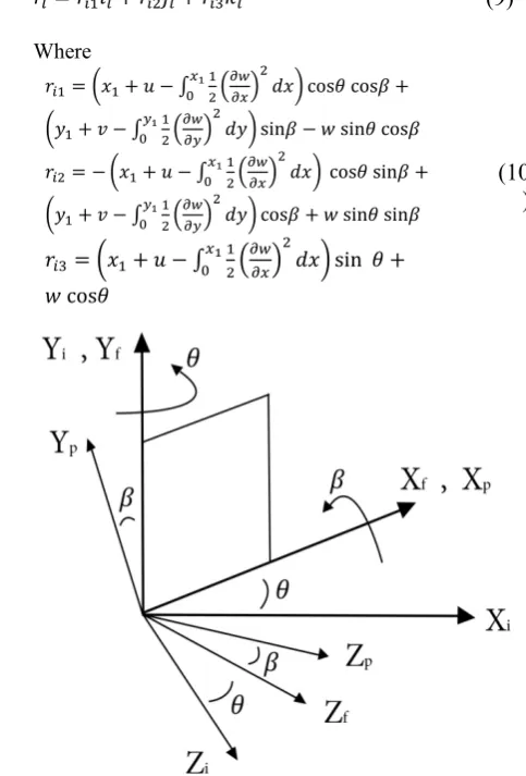
The position vector, , assigned to a point on the wing with coordinates ( , ) in the inertia reference frame can be determined by considering the whole plate movement through the matrix transformation [21]. For this purpose, the flapping and pitching motions of the plate in conjunction with the assumed reference frames are shown in Fig. 2. it should be noted that the origin of the inertial reference frame (X , Y, Z ) is located at the center of rotation. The angle indicates the rotation of the flapping reference frame (X , Y, Z ) about the Y axis as shown in this figure. Also, the pitching reference frame is obtained by rotating the flapping reference frame by the pitch angle about the X axis.
= + + (9)
Where
= + − cos cos +
+ − sin − sin cos
= − + − cos sin +
+ − cos + sin sin
= + − sin +
cos
(10 )
Figure 2. Pitching and flapping movement of the plate
where, and indicate the flapping and pitching rotation angles, respectively. Also, the integral terms show the effect of foreshortening on the displacement vector. It should be noted that, considering these terms is necessary for including the effect of dynamic stiffness.
The first variation of the kinetic energy is then obtained from the following equation,
= . (11)
Where is the material density. By substituting the velocity vector, Eq. 8, into Eq. 11, one can obtain the mass and dynamic stiffness statements which will be introduced in the next section.
The only force that plays a role in the virtual work statement is the aerodynamic load. Thus, this work can be determined by
= . (12)
Aerodynamic load
In this section, an aerodynamic load statement is developed by using a quasi-steady aerodynamic model in a simple manner. For this purpose, the aerodynamic lift can be written as:
= = × 2 ×∝ (13)
where is the air density, is free steam velocity, indicates reference area and ∝ shows effective angle of attack which is defined by the ratio of downwash and free stream velocities. Thus, the determination of downwash is a necessary item. For this purpose, the forward flight velocity vector of a flapping wing is defined by
= + + × (14)
where is the free stream velocity vector, is the velocity vector due to elastic deformations of the wing and Ω × r is the velocity vector due to the rigid rotational motion of the wing. Substituting each mentioned quantity into Eq. 14 gives
= + ( + ) + + − (15)
Also, downwash will be obtained by
= ∙ (16)
where is the normal vector perpendicular to the flow velocity and obtained by [21]
= + × = + + × (17)
where k is the unit normal vector in Z direction. and are the elastic rotation and rigid rotation vectors, respectively, that can be defined as:
= − + ,
= +
(18)
Substituting Eqs. 15 and 17 into Eq. 16 results in
= − − ( + ) + +
+ −
(19)
So, the effective angle of attack is defined by
∝ = − = − + 1 + +
− + −
(20)
Substituting Eq. 20 into Eq. 13 provides the lift stat ement in terms of the deformation state and rigid motions of a flapping wing.
Finite element formulation
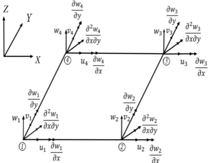
In this section, by incorporating the FE formulation based on the BFS element into the aforementioned relations, , and , the discretized form of a flapping wing equation of motions is introduced. The BFS element is first introduced by Bogner, Fox and Schmidt [20] and it has four nodes and six degrees of freedom per node (Fig. 3). It must be noted that the local coordinate (xyz) is located at the center of each element. The in-plane deformation field (u and v) within each element is interpolated according to the following relation:( , , ) = ∑
( , , ) = ∑ (21)
Also, the bending deformation is stated by
( , , ) = + + + +
+ + + + +
+ + + +
+ +
(22)
The unknown constants c will be obtained by substituting the sixteen known nodal deformations in Eq. 22. Thus, the resultant relation can be expressed in terms of the nodal shape functions similar to Eq. 21. The total displacement components can be shown in a matrix form:
× =
×
× or Δ =
(23)
where N1, N2 and N3 are the shape function
groups related to , and , respectively (see more details in [8]).
14
/
Journal of Aerospace Science and TechnologyVol. 11/ No. 1/ Winter-Spring 2017 H.Shahverdi,A.S.Nobariand H.BahramiTorabi
To achieve the discretized form of the governing equation of motions, one may need to substitute the interpolated displacement field, Eq. 23, into the related terms which were derived in the previous sections. This process is started from the terms of ϵ and k in Eq. 4 as introduced here.
ϵ =
0 0
0 0
0
= Γ Δq (24)
=
0 0 −
0 0 −
0 0 −2
= Γ Δ (25)
By substituting Eq. 23 into Eqs. 24-25, one can obtain the following relation:
ϵ = Γ =
= Γ =
(26)
where the elements of H and H matrices are explicit functions of x and y coordinates within each element, and relate the nodal DOFs to the strain field within the element.
By substituting Eq. 26 into Eq. 5, Eq. 8 into Eq. 11, and Eq. 20 and 13 into Eq.12, the δ , δT and
δ of a master element can be achieved in terms of nodal DOFs. Then, substituting the resultant first variational statements into Eq. 1 provides the elemental mass, gyroscopic damping, stiffness and dynamic stiffness matrices along with the elemental force vector of a single element as follows ([8], [21]):
= ℎ 1 1 + 2 2 +
3 3 )
(27)
= ℎ(2 ( 1 3 − 3 1)+
2sin ( 3 2 − 2 3)+
2cos ( 2 1 − 1 2)+
1 3 − 2 3 + 3 3
(28)
= + +
+
(29)
− 2
= ℎ − sin +
cos + − sin −
+ − +
cos ) − +
( − ) +
sin cos ( + ) +
sin ( − ) +
2cos ( ) + cos ( −
) + 2sin ( )
(30)
= ℎ sin − sin cos +
) + + cos −
cos + cos − 2sin +
+
− +
(31)
where
= ℎ
=
(32)
It should be emphasized that the underlined expressions, in above equations, indicate the contribution of the considered aerodynamic
model. Also, and represent dynamic
stiffening matrices in x and y direction due to foreshortening which is defined by
= , ,
= , ,
(33)
considered by the well-known penalty method [22] in the FEM. Thus, the resultant aeroelastic equations of a flapping wing can be written in the following matrix form:
+ + ( + ) = (34)
where q and F are the global degrees of freedom and force vectors, respectively. It must be noted that to account the integral terms which appeared in the above matrices and vector expressions, the two-dimensional Gauss quadrature rule with 5×5 Gauss points is utilized.
Results and discussion
In this section two different test cases are considered to validate and the reliability of the developed tool. In this regard, the structural dynamics behaviors of a non-rotating and rotating flat plate, as the first test case, are studied via modal analysis. Also, the effect of dynamic stiffening terms on the modal characteristics is investigated. Then, the root bending moment and shear force of an insect wing as the second test case is determined and compared with the available results.
First test case
To validate the structural dynamics behavior of the developed tool, a cantilevered rectangular flat plat as is considered here. The geometrical and material properties of this test case are presented in Table 1.
Table 1. Geometrical and material properties of the rectangular flat plate
Parameter Value
E(GPa) 70
G(GPa) 27
(Kg/m3) 3000
0.3 Length , (m) 1 Thickness, (m) 0.0025
Width , (m) 0.5
In order to compute the natural frequencies of the plate, the homogenous form of Eq. (33) without dynamic stiffening term is considered as follows:
+ = 0 (35)
The eigenvalues of Eq. (35) can be determined via standard eigen-solver routines.
So, the first 4 frequencies of the non-rotating plate are shown in Table 2 in comparison with ANSYS software. The obtained results show a good correlation with those by ANSYS. It should be noted that the ANSYS finite element modeling of the plate has been generated using shell elements (shell 181) with six degrees of freedom per node.
Table 2. The first four frequencies of the non-rotating plate
Mode Number
Frequency (Hz)
Percentage Error (%) Present
Method ANSYS
1 2.004 2.0034 0.03 2 8.641 8.6267 0.16 3 12.517 12.781 2.06 4 28.142 28.494 1.23 5 4.584 4.5811 0.063
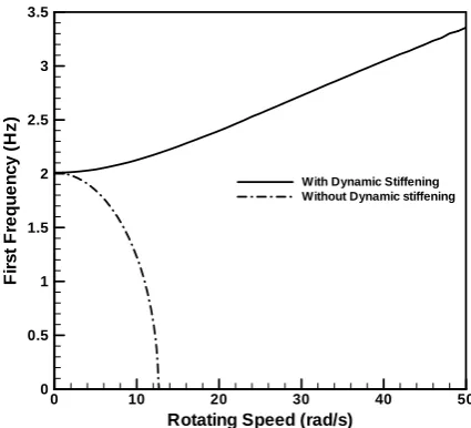
Then, the effect of dynamic stiffening on the dynamical behavior of the rotating plate is investigated here. For this purpose, the first and second natural frequencies of the rotating plate are depicted versus rotational speed in Figs. 4-5, respectively. As it is evident from these figures, the first and second frequencies of the rotating plate increase with the increase in the rotational speed under the influence of dynamic stiffening term, while these frequencies will show a decreasing trend with removing the dynamic stiffness term. It can be concluded that the foreshortening terms play an important role in increasing the stiffness of a rotating plate.
Figure 4. First frequency of rotating plate Rotating Speed (rad/s)
F
irs
t
F
re
q
u
e
n
c
y
(H
z
)
0 10 20 30 40 50
0 0.5 1 1.5 2 2.5 3 3.5
16
/
Journal of Aerospace Science and TechnologyVol. 11/ No. 1/ Winter-Spring 2017 H.Shahverdi,A.S.Nobariand H.BahramiTorabi
Figure 5. Second frequency of rotating plate
To validate the structural response of the rotating plate, the spin-up motion of a cantilever one is studied, as shown in Fig. 1. The function of rotational speed is considered by:
=
− sin 0 ≤ ≤
>
(36)
Fig. 6 shows the tip deflection with respect to time at ω = 10. The results show a very good agreement with those of Ref. 8. The results also reveal the importance of including dynamic stiffening effect for correctly capturing the response of a rotating plate.
Figure 6. Dynamic response of the insect wing
Second test case
The investigation of the obtained results reveals the accuracy and validity of the developed computational tool in the structural dynamics behavior point of view. Now the present model
can be surely taken into account to investigate the aeroelastic or dynamic response of the flapping plate (wing) under an aerodynamic load. For this purpose, a specified flapping insect-like wing is considered. Fig. 7 shows the finite element modeling of this wing which is created using 311 BFS elements. Also, Table 3 indicates the geometrical and material properties of this wing.
Figure 7. Finite element modeling of the insect wing [8]
Table 3. Geometrical and material properties of the insect wing
Value Parameter
60
EAluminum (Gpa)
7
EMylar (Gpa)
2400
Aluminum (kg/m3)
ρ
1250
Mylar (kg/m3)
ρ
0.33
Aluminum
υ
0.25
Mylar
υ
0.000508
tAluminum (m)
0.000104
tMylar (m)
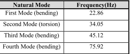
The first four natural frequencies of the insect wing are computed and listed in Table 4.
Table 4. The first four frequencies of the insect wing
Frequency(Hz) Natural Mode
22.86 First Mode (bending)
34.05 Second Mode (torsion)
45.12 Third Mode (bending)
75.92 Fourth Mode (bending)
R otating Speed (rad/s)
Se
c
o
n
d
F
re
q
u
e
n
c
y
(H
z
)
0 10 20 30 40 50
7 7.5 8 8.5 9
W ith D ynamic S tiffening W ithout D ynamic S tiffening
Time (s)
Ti
p
D
e
fl
e
c
ti
o
n
(m
)
0 2 4 6 8 10
-0.04 -0.03 -0.02 -0.01 0 0.01
Present (With Dynamic Stiffening) Present (Without Dynamic Stiffening) [8] (With Dynamic Stiffening) [8] (Without Dynamic Stiffening)
In order to validate the resultant loads of this wing, the bending moment and shear force at the wing root are determined using Newmark’s method through the prescribed flapping motion depicted in Fig. 9. It should be noted that the time step size is set to 0.001s. Fig. 10 shows a comparison of the computed results with those numerical and experimental results reported in [8] at various flapping frequencies. It should be noted that the results which are presented in [8] were determined by using a complete unsteady aerodynamic model. The developed aerodynamic model in the present study is very simpler than
that one used in [8]. The obtained results of two models have a similar trend and are close to each other. It is found that, the difference between the results of the present quasi model and the complete unsteady aerodynamic [10] models at lower flapping frequency ( less than 9.07 Hz) is not impressive. Thus, one can use the quasi-steady aerodynamic model to analyze the aeroelastic behavior or loads at low flapping frequencies. Also, it is found that increasing the frequency of flapping motion enhances the magnitude of shear force and bending moment.
Figure 9. Flapping and pitching motions at 11.6 Hz [8]
t/T
(r
a
d
)
0 0.2 0.4 0.6 0.8 1
-1 -0.5 0 0.5 1
t/T
(r
ad
)
0 0.2 0.4 0.6 0.8 1
0 0.5 1 1.5 2 2.5 3
t/T
(r
ad
/s)
0 0.2 0.4 0.6 0.8 1
-1 -0.5 0 0.5 1
t/T
(r
ad
/s
)
0 0.2 0.4 0.6 0.8 1
-2 -1 0 1 2 3
t/T
(r
ad
/s
2)
0 0.2 0.4 0.6 0.8 1
-60 -40 -20 0 20 40 60
t/T
(r
ad
/s
2)
0 0.2 0.4 0.6 0.8 1
18
/
Journal of Aerospace Science and TechnologyVol. 11/ No. 1/ Winter-Spring 2017 H.Shahverdi,A.S.Nobariand H.BahramiTorabi
Figure 10. Root bending moment variation at different
flapping frequencies Figure 11. Root shear force variation at different flapping frequencies
Time (s) Be n d in g M om e n t (N .m )
0 0.02 0.04 0.06 0.08 0.1
-0.1 -0.05 0 0.05 0.1 Experiment Present method Ref [10]
f= 9.07 Hz
Time (s) S h ear F o rc e (N )
0 0.02 0.04 0.06 0.08 0.1
-0.006 -0.004 -0.002 0 0.002 0.004 0.006
f= 9.07 Hz
Time (s) Be nd in g M o m e n t (N .m )
0 0.02 0.04 0.06 0.08
-0.15 -0.1 -0.05 0 0.05 0.1 0.15 Present method Experiment Ref [10]
f= 10.58 Hz
Time (s) Be ndi ng M o m e nt (N .m )
0 0.02 0.04 0.06 0.08
-0.15 -0.1 -0.05 0 0.05 0.1 0.15 0.2 Present method Experiment Ref [10]
f= 10.96 Hz
Time (s) B e nd in g M om e n t (N .m )
0 0.02 0.04 0.06 0.08
-0.4 -0.3 -0.2 -0.1 0 0.1 0.2 0.3 0.4 Present method Experiment Ref [10]
f= 11.6 Hz
Time (s) Sh e a r F o rc e (N )
0 0.02 0.04 0.06 0.08
-0.004 -0.002 0 0.002 f=10.58 Hz Time (s) S h ear F o rc e (N )
0 0.02 0.04 0.06 0.08
-0.003 -0.002 -0.001 0 0.001 0.002 0.003
f= 10.96 Hz
Time (s) S h ear F o rc e (N )
0 0.02 0.04 0.06 0.08
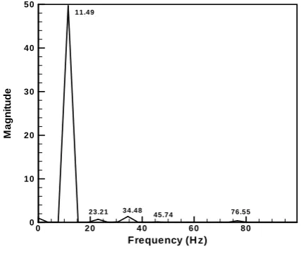
The Fast Fourier Transform (FFT) analysis of the computed root bending moment at 11.6 Hz is performed and the contribution of the effective modes is presented in Fig. 12. As it is evident, the first and second mode shapes of the wing have more contribution to the bending moment than the other mode shapes. However, the effect of the rigid body rotation or the related dynamic loads on the bending moment is very significant.
Figure 12. FFT results
Conclusions
A computational tool for the aeroelastic analysis of flapping wings was developed in this study. In this regard, a finite element model based on BFS element was established to simulate the structural dynamic behavior of flapping wings. Also, dynamic stiffening term due to foreshortening effect was considered. The aerodynamic loads were estimated using the developed quasi-steady aerodynamic model. To validate the structural dynamic behavior, the modal and transient analyses of a specified plate were performed. The obtained results revealed the accuracy and fidelity of the developed FEM tool. Also, the results showed that the foreshortening effect enhances the natural frequencies of a rotating plate by increasing the rotational speed.
Indeed, the aeroelastic analysis of an insect-like wing showed that the contribution of the inertial effect is greater than that of the elastic effect in the load determination process. However, the first pure bending and pure torsion mode shapes have a considerable contribution in the root loads than the other mode shapes. The shear force and root bending moment increase by
increasing the flapping frequency. Also, the use of quasi-steady aerodynamic will result in acceptable results and decrease computational efforts in low flapping frequencies (less than 9.07 Hz).
References
[1] DeLaurier, J. D., "An Aerodynamic Model for Flapping Wing Flight," Aeronautical Journal, Vol. 97, No. 964, 1993 pp. 125-130.
[2] Gogulapati, A., Friedmann, P.P. and Shyy, W., "Nonlinear Aeroelastic Effects in Flapping Wing Micro Air Vehicles," 49th AIAA/ASME/ASCE/AHS/
ASC Structures, Structural Dynamics, and Materials Conference, Schaumburg, Illinois, 2008, pp. 1-27.
[3] Ke, S., Zhigang, W. and Chao, Y., "Analysis and Flexible Structural Modeling for Oscillating Wing Utilizing Aeroelasticity," Chinese Journal of Aeronautics, Vol.2, No.1, 2008, 402-410.
[4] Kim, D. K., Lee, J. S., Lee, J. Y. and Han, J. H., "An Aeroelastic Analysis of a Flexible Flapping Wing Using Modified Strip Theory," SPIE’s 15th
Annual Symposium Smart Structures and Materials & Non-destructive Evaluation and Health Monitoring, San Diego, California, 6928 (69281O), 2008, pp. 1-8.
[5] Lakshminarayan, V. K. and Farhat, C., "Nonlinear Aeroelastic Analysis of Highly Flexible Flapping Wings Using an ALE Formulation of Embedded Boundary Method," AIAA 2014-0221, AIAA Science and Technology Forum and Exposition (SciTech 2014), National Harbor, Maryland, 2014, pp.13-17.
[6] Daniel, T.L. and Combes, S. A., "Flexible Wings and Fins: Bending by Inertial or Fluid Dynamic Forces," Integrative and Comparative Biology,
Vol.42, 2002, pp. 1044–1049.
[7] Combes, S. A. and Daniel, T. L., "Into Thin Air: Contributions of Aerodynamic and Inertial– Elastic Forces to Wing Bending in the Hawkmoth Manducasexta," Journal of Experimental Biology, Vol. 206, No. 17, 2003, pp. 2999-3006.
[8] Singh, B., Dynamics and Aeroelsticity of Hover Capable Flapping Wings Experiments and Analysis, (Ph. D Thesis), Department of Aerospace Engineering, University of Maryland, USA, 2006.
[9] Toomey, J. and Eldredge, J. D., "Numerical and Experimental Study of the Fluid Dynamics of a Flapping Wing with Low order Flexibility,"
Physics of Fluids, Vol. 20, 2008, pp. 1–10.
Frequency (H z)
M
a
g
n
it
ude
0 20 40 60 80
0 10 20 30 40 50
11 .4 9
23 .2 1 3 4 .4 8
20
/
Journal of Aerospace Science and TechnologyVol. 11/ No. 1/ Winter-Spring 2017 H.Shahverdi,A.S.Nobariand H.BahramiTorabi
[10] Gogulapati, A. and Friedmann, P.P., "Approximate Aerodynamic and Aeroelastic Modeling of Flapping Wings in Hover and Forward Flight," 52nd AIAA/ASME/ASCE/ AHS/ASC
Structures, Structural Dynamics and Materials Conference, Denver, Colorado, 20011.
[11] Nakata, T. and Liu, H., "A Fluid–structure Interaction Model of Insect Flight with Flexible Wings," Journal of Computational Physics, Vol. 231, 2012, pp. 1822–1847.
[12] Yang, W.Q., Song, B.F., Song, W.P. and Wang, L. G., "The Effects of Span-wise and Chord-wise Flexibility on the Aerodynamic Performance of Micro Flapping-wing," Chinese Science Bulletin, Vol. 57, No. 22, 2012, pp. 2887-2897.
[13] Pourtakdoust, S.H. and Karimain Aliabadi, S., "Evaluation of Flapping wing Propulsion Based on a new Experimentally Validated Aeroelastic Model," Scientia Iranica, Transition B: Mechnical Engineering., Vol. 19, No. 3, 2012, pp.472–482.
[14] Gordnier, R., Chimakurthi, S., Cesnik, C. and Attar, P., "High-Fidelity Aeroelastic Computations of a Flapping Wing with Spanwise Flexibility,"
Journal of Fluids and Structures, Vol. 40, 2013, pp. 86-104.
[15] Heathcote, S., Wang, Z. and Gursul, I., "Effect of Span Wise Flexibility on Flapping Wing
Propulsion," Journal of Fluids and Structures,
Vol. 24, No. 2, 2008, 183-199.
[16] Lee, N., Lee, S., Cho, H. S., Kwak, J.Y. and Shin, S.J., "Computational Analysis for Flapping Wing by Coupled CFD and CSD Solutions," 29th
Congress of the International Council of the Aeronautical Sciences (ICAS), St. Petersburg, Russia, 20014.
[17] Xue, D., Song, B. F, Yang, W. Q. and Fu, P., "Structural Damping Effect on Deformation of Flexible Flapping Wing," Asia-Pacific International Symposium on Aerospace Technology (APISAT2014), Shanghai, China, 2014.
[18] Qi, D. and Gordnier, R., "Effects of Deformation on Lift and Power Efficiency in a Hovering Motion of a Chord-wise Flexible Wing," Journal of Fluids and Structures, Vol. 54, 2015, pp.142–170.
[19] Meirovitch, L., Principles and Techniques of Vibrations, 1th Ed., Prentice Hall, London.
[20] Reddy, J. N., Mechanics of Laminated Composite Plates, 2nd Ed, CRC Press, London, 2004.
[21] Bahrami Torabi, H., Study of Aeroelastic Behavior of Flapping Wings, (M.Sc. Thesis), Department of aerospace engineering, Amirkabir University of Technology, 2012.

![Figure 9. Flapping and pitching motions at 11.6 Hz [8]](https://thumb-us.123doks.com/thumbv2/123dok_us/8946338.1855706/9.595.105.511.279.737/figure-flapping-pitching-motions-hz.webp)