Remote Automatic Meter Reading System
https://doi.org/10.3991/ijoe.v13i10.6751Wenbin Zheng, Zhe Yang, Lei Feng!!", Ping Fu Harbin Institute of Technology, Harbin, China
Abstract—This paper designed a remote wireless automatic meter reading device to achieve the actual needs of users such as transform data as the set time, history report, monitoring status of the meters and so on. STM32 (32-BitSTMicroelectronics Microcontroller) series single chips work well as the core control devices to satisfy the requirements, combined with surveillance cameras and a 3G wireless module to complete the hardware circuit design, which includes an STM32 control circuit, sensor data acquisition part, a 3G wireless module interface section, the analog video signal processing section and the analog video signal processing section. The software was designed ac-cording to the users’ needs, support multi-network system as well as upload pic-tures and parameters in time, the test results show that the device satisfied the requirements and could be used in the resource monitoring directly. This paper describes the overall design, the design of the hardware and software, calibrat-ing device and testcalibrat-ing device.
Keywords—Remote Wireless Automatic Meter Reading (RWAMR), Multi-network Standard, 3G, Smart City
1
Introduction
The development of automatic meter reading technology is closely connected with the development of electric power, electronics, computer and wireless communication technology, which is used to remote reading the consumption of gas, water, oil, elec-tricity and so on. This technology first appeared in the European and American coun-tries [1]. United States in 1986 founded the association for the study of automatic meter reading AMRA (Automation Meter Reading Association) [2] after nearly 30 years of developments, automatic meter reading scale gradually expanded. European countries are also unwilling to lag behind in this field, with the EUROAMRA (Europe Automation Meter Reading Association) and UKAMRA (United Kingdom Automa-tion Meter Reading AssociaAutoma-tion). Automatic meter reading technology has been ap-plied more and more widely in the power enterprise [3].
carrier, remote meter reading meter [7, 8]. The current application in the water supply industry still stays in artificial meter reading way. The contemporary application of the meter reading still has the following problems: limitations of water meter manu-facturers, bad environment, the cable network mode can't satisfy the needs of remote data collection, and line construction complex problems still exist [9]. Laying new water pipes with modern metering systems in pace of the existing water pipes would present an enormous cost and logistics challenge to the government, while possibly disrupting the daily lives of residents. However, there is a need for a new way of reading the meters other than the manual way presently being used. The solution provided must be convenient and low cost. The device should be strong, real-time and have stable communication transmission, fast response and low power consumption, replacing the traditional manual meter reading. The traditional manual meter reading method is inefficient and costly. The real-time availability and accuracy of the data can’t be guaranteed either.
Wireless meter reading technology is a process by devices that can automatically read and process data using wireless communication and computer network technolo-gy in a special way. Compared with the traditional meter reading technolotechnolo-gy, it not only saves the human resources, but the cost as well and helps the management de-partment to discover problems and take appropriate measures [10, 11].
Wireless automatic meter reading systems are based on the following wireless communication technologies: GSM (Global System for Mobile Communication, the global mobile communication system), GPRS (General Packet Radio Service), and infrared, Bluetooth and ZigBee [12]. GSM [13, 14] and GPRS, compared to other ways, have the advantages of stable transmission and communication distance [15- 17]. The wireless transmission distance of ZigBee communication technology is short, generally between 10-100m. The project reported in this paper covered areas far away from cities with servers at least a few kilometres to tens of kilometres away. Therefore, GSM and GPRS were chosen for communication.
2
Overall Design of RWAMR Module
In order to satisfy the requirements of the project, the hardware specifications of the device are as follows. The wireless network should support 2G (GSM, CDMA) and 3G (W-CDMA) and the function of system supports video capture with multi-plexed channel camera input interfaces, picture taken and uploaded regularly, 4-channel 4-20mA current input measurement, accuracy 0.1mA, to detect the current and 12V supply voltage measurement, accuracy 0.1V. The device needs a RS232 interface, two RS485 interfaces and an 8G Micro SD card interface. Besides, it should be able to configure the parameters through the server or the serial port and its maxi-mum working power consumption is 2W, standby power consumption is 20 mW.
According to the above indicators, this paper completed the overall design of the block diagram in Figure 1. RWAMR device is comprised of two parts that are the substrate and carrier boards. MCU (Micro Control Unit) as the core control device controls the work of the external circuit and data acquisition. MCU is connected with 3G wireless module through the serial port, and control 3G module in accordance with the AT (attention) instruction. The 4-channel cameras are attached to the input channel of the 4-to-1 analog switch. The MCU controls the working channel and analog signals collected by video processing circuit. The wireless module controls the video decoding chip to decode the video or image data, and the data are stored in the SD card. 3G wireless module establishes a FTP (File Transfer Protocol) connection and uploads the image data to the FTP server. Using of the STM32 internal ADC (Analog-to-Digital Converter) can monitor the supply voltage of 12V, turn 4-20mA current into voltage through the precision sampling resistor, and then through the low-pass filter and the voltage follower, input voltage to the MCU ADC channel. So the current can be indirectly measured. On the carrier board, there are a wireless module interface and a video processing circuit. The SD card used is still mounted on the base board under the wireless module SD card. In order for the SD card to be installed under the wireless module on the carrier board, use a 2 of 1 analog switch on the SD card interface circuit and all of these are controlled by MCU.
MCU Temperature
measurement circuit Voltage measurement
circuit Parameter modification
Interface
Digital input
3G module
Video processing
circuit
Multi-channel video input
SD card
SIM card
Antenna interface
Fig. 1. Hardware Overall Design Diagram
initialize
Serial port modificates parameters (optional)
Synchronizate time, parameter
Video capture (optional)
Sensor signal measurement
Take pictures and upload
Upload parameters
Save picture parameters (optional)
Upload historical data
Video capture (optional) Power on, switch input
Finished shooting?
Y
N
Voltage and temperature
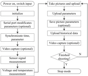
measurement Stop mode Fig. 2. Software Overall Design Flowchart
3
Hardware Design of RWAMR
ports (wireless module requires two serial ports. RS485 channel requires two serial ports. Serial port to modify the parameters part need 1 serial port), RTC, external interrupt input interface, IO (Input/Output) control interface. So STM32F103RC whose core is Cortex-M3 is used as the core control device. Its frequency can be up to 72MHz.
The kind of camera decides the resolution of the picture. Compared to USB (Uni-versal Serial Bus) camera and serial camera, the surveillance camera used in this de-sign has such advantages:
• The using of analog video signal transmission has strong anti-jamming ability in the signal transmission process.
• Video capture can be simple to achieve with the control of 3G module by using camera and video processing chip AK8856 program.
• Analog camera technology is stable. The huge number of the manufacturer market, low cost, mass production will not cause the supply problems of microcomputer production.
Due to poor industrial environment and the need of the power, the camera needs a long lead and anti-interference ability. USB camera can’t guarantee the requirement of the situation. In view of the above analysis, the design selected the surveillance camera.
The choice of 3G wireless module also has to adapt to the need of multi-network. This design requires 3G wireless module to support China Mobile and China Unicom, the two kinds of mobile communication network. The design of the program is the camera's output directly connected with the 3G wireless module. STM32 sends com-mands to control the work of the camera through the serial port. SIM5215E, devel-oped by SIM Group, is fully compliant with the above requirements.
This device has a minimum system based on MCU chosen which includes JTAG (Joint Test Action Group) debug interface circuit, reset circuit, crystal oscillator cir-cuit, chip Flash W25X16 circuit.
The five serial ports of STM32 are used for parameter modification, controlling 3G wireless module, RS485 data reception. The reset circuit adopts "RC (Resistance and Capacitor) power-on reset" structure [18].
3G module used SIM5215E version, which is fully compatible with the interface, which can support different network formats if only need to replace the 3G module and SIM card.
The peripherals that are mounted below the 3G wireless module are shown below: Micro SD card, Camera interface, SIM (Subscriber Identification Module) card and Serial port communicated with STM32.
One of the required function is the video processing before sending to the server. We have to choose one chip to pretreatment. SIM5215E has a digital image input interface, supporting 4:2:2 8bit YUV model [19], which can directly input image data generated from video processing chip.
AK8856’s work is decoding NTSC (National Television Systems Committee) or PAL (Phase-Alternative Line) mixed video signal to digital video data, and outputs a digital signal compatible with Y, Cb and Cr signal. The 3G module uses IIC (Inter-Integrated Circuit) bus to control the work of AK8856.
STM32 will send a series of commands when need pictures or videos, and the wireless module transformed these orders into other formats that can be identified by AK8856, specific controlling process is completely transparent to the user.
4
Software Design of RWAMR
4.1 Remote Synchronization Time and Parameter Configuration
Parameter configuration via serial interface is mainly used to write information such as device number, FTP related parameters, and current measurement calibration parameters when a new board needs to be configured. First, initialize the STM32 serial port 1and send data to the host computer to receive data request. Determine the validity of the data after the data obtained from the host computer. The chip will de-termine the validity of the data, when the data from the host computer to obtain. The host computer will send the data again after the data is sent to the host computer again. Then the data will be sent to the host computer again and the host computer will send the data again. If the device considers that the host computer update parame-ter operation has been completed, send "INI Parameparame-ter Finished" to the upper com-puter to indicate that the modification parameter is successful. Otherwise, send the error message to indicate that the modification parameter operation has failed. After the parameter information is successfully obtained from the host computer, it is also necessary to write the parameters to Flash.
Set up TCP connection
Send the device number
Get the return data
Perform MD5 checksum
Obtain time data Check consistent? Y N Y N Parameter configuration? Get the configuration parameters Close TCP connection
Set up TCP connection
Send response data Set the failure flag
Close TCP connection Set PDP
Close PDP
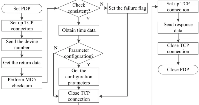
Fig. 3. The Flowchart of the Software Design of Remote Synchronization Time and Configu-ration Parameters
The remote parameter configuration operation is combined with the time synchro-nization operation to acquire the configuration data of the device while obtaining the time data. According to the format agreed in advance, it is possible to judge whether the synchronization operation needs to update the configuration parameters. Accord-ing to the device technical index analyzed in Section 2, the flowchart of the software design of remote synchronization time and configuration parameters is shown in Fig-ure 3.
4.2 Parameter Operation Updating and Picture Upload
The required parameters value must be update first to the server to record the in-formation and data, the device number, upload interval, camera channel, and so on are the default values, when the device leaves the factory. For different devices, the user need to modify the parameters ether using the serial port or the setting button on FTP to obtain the parameters.
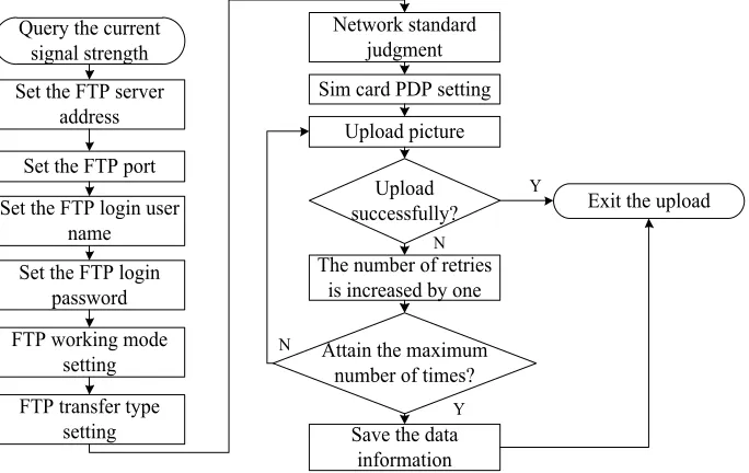
This sub-function will update the parameters and put them into the device, turn on the power to run in accordance with the new parameter configuration. In a working cycle, after access to such parameters, the parameters will be stored in the off-chip Flash W25X16. STM32 can also save the parameters when the power off. The flowchart of the work is shown in Figure 4.
Picture shooting and video are sharing a four-channel camera. The configuration parameters determine the camera to take pictures or take pictures. FTP (File Transfer Protocol) is an abbreviation of the text transfer protocol. FTP can be used to easily share files between hosts. FTP client is used to issue commands to the server to down-load files, updown-load files and delete files on the server.
W25X16 reads data W25X16 is normal and not updated parameters?
Y
N
Data validity judgment?
Invalid
Valid
Update the parameter Read status flag
Return
Fig. 4. The Flowchart of W25X16 Updating Parameter Operation
N
N
Y
Y Set the FTP server
address
Set the FTP port Set the FTP login user
name Set the FTP login
password FTP working mode
setting
Sim card PDP setting Upload picture
Upload successfully?
Attain the maximum number of times? The number of retries
is increased by one
Save the data information FTP transfer type
setting Query the current
signal strength
Exit the upload Network standard
judgment
5
Calibration and Testing of the Device
The device voltage measurement and current measurement are used within the STM32 ADC. The input of each channel was calibrated.
5.1 Calibration of the Device
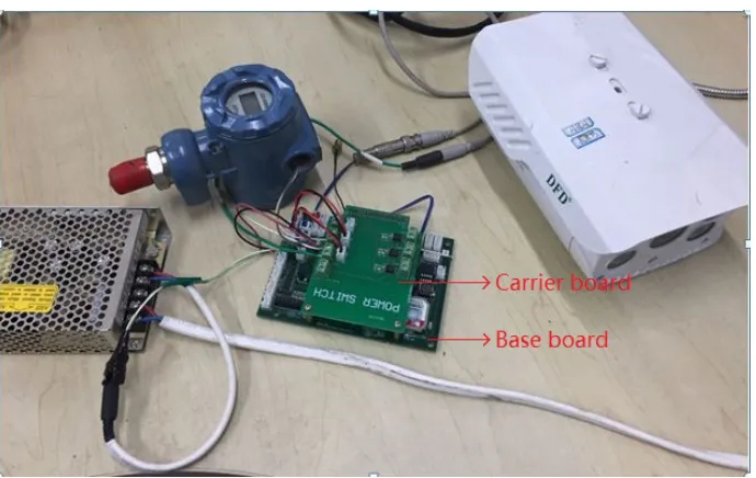
As shown in Figure 6, the board is composed of the base board and the carrier board.
Fig. 6. Wireless Automatic Meter Reading System
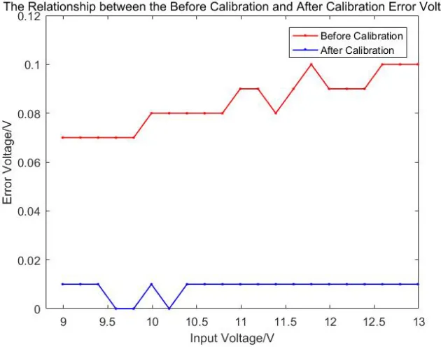
The source of error comes from the following aspects. The impact of the reference source: 3.3V output voltage accuracy of PT1102 is connected with the resistance value accuracy of the power circuit. Due to the discreteness of the resistance value, output voltage values of the same batch of different board are in different. The impact of ADC noise itself: the noise inside the ADC will affect the quantization accuracy, which may come from the environment, but also from the impact of temperature changes. The output noise of the operational amplifier: it introduces noise using the operational amplifier as the voltage follower in the measurement of 4-20mA input.
Device to be measured
Agilent E3631A voltage source
Computer
VICTOR-05 current source
Agilent 34410A desktop multimeter
Fig. 7. Current Calibration Circuit
As shown in Figure 7, the current measurement calibration circuit is established by the current source, power supply, desktop multi-meters, to be calibrated board and computer.
Fig. 8. The Relationship between the Before and After Calibration Error Voltage
Figure 9 shows the current values entered on Channel 1 for one of the boards and the measured current values before and after calibration.
As can be seen from the Figure9 above, the actual measured current value before calibration is smaller than the input current value, the maximum difference of 0.26mA, after the least squares calibration, only a maximum of 0.01mA voltage measurement error. This shows that the results of current measurement channel cali-bration meet the accuracy requirements of 0.1mA.
In summary, it can be seen that the deviation is large compared the measured pre-calibration value and the theoretical value, the error beyond the specified range. After calibrate the vale measured is approximately the same as the theoretical measured value, and the error is less than the specified range. It indicates that this method has achieved good results.
Fig. 9. The Relationship between the Before and After Calibration Error Current
5.2 Function Test of the Device
The Test of Serial Port Parameters!First of all the device sends the request of configuration parameters "Please input parameters:". And then enter the parameters to be configured in the string input box. The type of parameter is based on the beginning of the first two bit.
configura-tion parameters and calibraconfigura-tion coefficients. After receiving the data, the device will judge the validity of the data. If valid, it will prompt "Set PAR Finished".
The above operation can show that the data with different beginning of the first two bit can be updated to the system. Before the test, original parameters is 1000025_04_010_2211481982500,1000025 is device number,04 is enabled camera number,010 means upload parameters every 10 seconds, 22114819825 is related parameters on FTP server. Enter 011000025_01_010_22114819825 after "Please input parameters:" appeared. The return parameter is 1000025_01_010_22114819825 after "Set PAR Finished". It is a successful operation through the serial port to modify the parameters.
The Test of Synchronization Time and Modifying Parameters Remote-ly!After the device powered on, it will establish a TCP connection with the server and sends the device number of the device to the server. The server returns the current system time, all the parameter data corresponding to this number device and the MD5 [20] value calculated from these characters. The device receives the current time 2016061321551601000023, which means the time is year: 2016, date: June, 13th; time: 21:55:16. And the last ‘01000023’ is the reserved data bits. The followed flag means whether the parameters have to be modified. "0" means no modification is needed, and the configuration parameters of the device are behind it.
Fig. 10.The Photo of Site survey
Fig. 11.The Photo of Site survey
After all the functional and performance tests, the results show that the design of the device to meet the technical requirements.
6
Conclusions
The design of the remote wireless automatic meter reading module according to the technical requirements, completed the hardware circuit design and related program design. First, STM32 was used in the controller selection, because the STM32 series MCU not only has ADC, rich serial resources and IO pins, but also has good low power consumption and low cost. In this device, its performance plays to the extreme. Next, communication part selected 3G wireless module of "SIMCom" company. It supports different network standards and its pin is fully compatible to facilitate the design of the device board. SIM5215E supports the camera data acquisition and de-coding control, reduces the cost of video signal acquisition and improves the reliabil-ity of the device.
The design of the device satisfies the requirements by the water factory. After a lot of production testing, the device runs in a good condition, and all the functions satisfy the function requirements. The result indicates the design of the expected objectives is completed.
7
Acknowledgment
This work is supported in part by the Online Education Research Funds of Online Education Research Center of Ministry of Education (Quantong Education) (Grant No. 2016YB132) and “the Fundamental Research Funds for the Central Universities” (Grant No. HIT NSRIF.20169), Heilongjiang Postdoctoral Fund (Grant No. LBH-Z16081) and CERNET Innovation Project (Grant No.NGII20160610).
8
References
[1]K.Aksela, M.Aksela, J. (2011). Demand Estimation with Automated Meter Reading in a Distribution Network. Journal of Water Resources Planning and Management, 137(5): 456-467.
[2]S Palaniappan, R Asokan, S Bharathwaj, N Sujaudeen, J. (2015). Automated meter read-ing system-a study, International Journal of Computer Applications, 116(18):39-46. [3]BD Sawarkar, MSS Golait, J. (2015). A Review Paper on Automatic Meter Reading and
Instant Billing, International Journal of Advanced Research in Computer and Communica-tion Engineering.
[4]Tao Fang, Liangzhong Fan, C. Remote Automatic Meter Reading System Based on CAN-BUS. Proceedings of 2010 2nd International Conference on Multimedia and Computation-al Intelligence (ICMCI 2010).
[5]Zhihua Li, KuiLiDong Cui, Yingchen Wang, C. Hardware Design of Automatic Meter Reading System Based on Internet. Proceedings of 2008 IEEE International Symposium on Knowledge Acquisition and Modeling Workshop.
[6]Al Farabi M, MahdalizaIdrus S, Zulkifli N, J. (2016). A Wireless Utility Meter System: Design and Implementation. Recent Patents on Engineering, 6 (1): 58-64.
[7]Xiaoyan Wang, Qiang Wang, Guodong Wang, J. (2006). Measurement and Analysis of Transmission Characteristics of Overhead Distribution Lines and Power Shielded Cables. Power System Communications.
[8]K Zhao, (2015) Analyses the Carrier Communication Technology in the Application of the Remote Meter Reading, Wireless Internet Technology.
[9]MJ Huang, D. (2016). Design and Implementation of Power Meter Remote Reading and Data Analysis System Based on GPRS, Jilin University.
[10]A Biranje, SS Lokhande, J. (2015). Wireless ARM-Based Automatic Meter Reading & control system (WAMRCS), International Conference on Pervasive Computing.
[11] G Yao, H Zhang, Q Chen, (2014). A wireless automatic meter reading system based on digital image process and ZigBee-3G.International Conference on System Science & En-gineering. pp 128-132.
[12]G Yao, HZ hang, Q Chen, J. (2014). A wireless automatic meter reading system based on digital image process and ZigBee-3G, International Conference on System Science & En-gineering, 6:128-132.
[13]S Male, J. (2014). A Smart Wireless Electronic Energy Meter Reading Using Embedded Technology, International Journal of Engineering Research & Applications, 4(1).
[14]Shijiong,Yuan, J. (2011). Remote wireless automatic meter reading system based on GPRS [J], IEEE International Conference on Communication Software & Networks, pp 667-669. [15]MF Gong, FJ Yin, YW Li, MR Li, ZG Wang, J. (2014). Design of Remote Wireless Meter
Reading System Based on ZigBee and GPRS, Electronics Quality.
[16]ZHH Jun, YS Zhu, J. (2015). Wireless Remote Water Meter Design of Automatic Meter Reading System, International Journal of Smart Home, 9(12): 289-298.
[17]CM Vidhyapathi, MCSKrishna, CHReddy, GK Reddy, J. (2014). Image processing based energy meter reading using ZigBee and GSM, International Journal of Engineering Re-search, 9(18): 4997-5006.
[19]TJ Liu, YC Lin, W Lin, CCJ Kuo, J. (2013). Visual quality assessment: recent develop-ments, coding applications and future trends, Apsipa Transactions on Signal & Information Processing.
[20]P Gupta, S Kumar, J. (2014). A Comparative Analysis of SHA and MD5 Algorithm, Inter-national Journal of Computer Science & Information Technology, 5(3):4492-4495.
9
Authors
Wenbin Zheng is a lecturer of School of Electrical Engineering, Harbin Institute of Technology, No.2 Yikuang Street, Harbin, Heilongjiang Province, China, 150080. He received doctor degree in 2014 from Harbin Institute of Technology. His main research interests are cooperative transmission, wireless sensor, network and automat-ic test and control technology, mautomat-icrofluidautomat-ic technology and etc.
Lei Feng is an associate professor of School of Electrical Engineering, Harbin In-stitute of Technology, No.2 Yikuang Street, Harbin, Heilongjiang Province, China, 150080.
Zhe Yang is a master degree candidate of School of Electrical Engineering, Harbin Institute of Technology, No.2 Yikuang Street, Harbin, Heilongjiang Province, China, 150080. He received bachelor degree in 2015 from Harbin Institute of Technology. His main research interests are wireless sensor, automatic test and control technology, Android application development and etc.
Ping Fu is a professor of School of Electrical Engineering, Harbin Institute of Technology, No.2 Yikuang Street, Harbin, Heilongjiang Province, China, 150080. He received his Doctor Degree from Harbin Institute of Technology in 1999. His main research areas are image processing, compressive sensing and automatic test technol-ogy and etc.