www.adv-radio-sci.net/11/277/2013/ doi:10.5194/ars-11-277-2013
© Author(s) 2013. CC Attribution 3.0 License.
Radio Science
Polarimetric radar cross section under SAR geometry
N. Phruksahiran and M. Chandra
Professorship of Microwave Engineering and Electromagnetic Theory, Chemnitz University of Technology, Germany Correspondence to: N. Phruksahiran (narathep.phruksahiran@s2009.tu-chemnitz.de)
Abstract. In this paper, the radar cross section of canonical scatter, with perfectly conducting surface, under the synthetic aperture radar geometry and polarized electromagnetic wave, has been considered and a new approach of polarized scat-tered electric field approximation for its evaluation has been developed.
1 Introduction
The synthetic aperture radar (SAR) system works by trans-mitting electromagnetic waves to the area of interest to sur-vey or surveillance in case of disaster monitoring. The elec-tromagnetic wave signals can be modified or modulated to increase the resolution in the range direction. The key fea-ture of the electromagnetic wave which used in polarimetric SAR system is the property of different reflection or scatter-ing mechanism dependscatter-ing on different types of the subject or target by using the polarization of transmitted and received wave.
The level or the strength of the reflected electromagnetic wave signal are different and are based on the roughness of the surface, the distance and the structure of the target on the ground. There are many researchers, who try to simulate and to do experiments about the reflection of electromagnetic waves from various objects.
In this paper, we present a new approach to calculate the polarimetric radar cross section of canonical targets which represent the structure of the ground surface, e.g., the flat plate, the dihedral reflector and the trihedral reflector repre-sent the flat surface, the fence along the border wall or forest and the urban structure, respectively. The radar cross section was determined under the SAR geometry and polarization of incident and scattered electric fields by using physical optic approximation and far field radiation.
This paper is organized as follows. In Sect. 2, we review some basic and the mathematical definitions of the scattering process, the radar cross section and the simulation of
scat-tered fields using physical optic approximation. The new ap-proaches of polarimetric radar cross section are presented in Sect. 3. The experimental model, i.e., the ground based SAR geometry which was used in this paper and the target model, are presented in Sect. 4. In Sect. 5, we present the simulation results of the flat plate, the dihedral reflector and the trihedral reflector. The conclusion is addressed in Sect. 6.
2 Basics
The scattering mechanism of the object in far field can be modeled as a linear transformation between incident electric fieldsEiand scattered electric fieldsEs, described by a
scat-tering matrix Spqas shown by Lee and Pottier (2009):
Es=e
−j kR R
Spq
Ei (1)
or
Es=
Esh Evs
=e
−j kR R
ShhShv SvhSvv
Ehi Evi
. (2)
Where the distance between the antenna and the scatter-ing object is R,k is the wavenumber. The term e−j kR/R describes the wave propagation effects in amplitude and in phase. The parameters Spq are the complex scattering am-plitude element of the scattering matrixSpq
, in which the indexq andpstand for the incident and scattered polariza-tion, respectively. The index handv denote the horizontal and vertical polarization basis of the wave.
2.1 Radar cross section
effective surface which describes the electromagnetic reflec-tivity of the target in the direction back to the radar. It de-pends on target structure, the frequency of signal and the po-larization of incident and scattered electrical fields. The radar cross section is generally defined by using power comparison between the incident wave and the reflected wave and can be calculated as follows:
σpq= lim R→∞4π R
2
E
s
p(θs, φs)
2
E
i
q(θi, φi)
2 . (3)
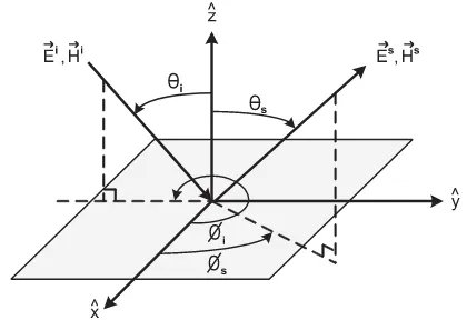
The angle designationθi, θs, φi and φs are presented in Fig. 1 by using the Cartesian coordinate systemx,ˆ yˆ andzˆ axis. It shows the direction of incident and scattered electric fields which was used in this paper. The angleθi is between thezˆaxis and the incident direction of the wave. The angle θs is between thezˆ axis and the scattered direction of the wave. The angleφi andφs can be determined by using the projection on the xy-plane with respect to thexˆaxis.
The components of scattering matrix
Spqare related to polarimetric radar cross sectionσpq and can be determined from the Eqs. (1) and (3) as follows:
σpq=4π
Spq
2
. (4)
2.2 Simulation of scattered fields using physical optic
In practice, the reflection on the perfectly conducting metal surface is considered. An important role is to determine the interaction between the incident waves and the scattering mechanism on the surface. In the physical optic approxima-tion, it can be assumed that the tangential component of the reflected magnetic field strength is equal to the tangential component of the incident magnetic field strength. So that the relationship between the current distribution on the scat-tering surfaceJs, the incident magnetic fieldHiand the unit
vector normal to the scatter surfacenˆ as shown by Balanis (1989):
Js=2nˆ×Hi (5)
The evaluation of the scattered electric field can be done by using the magnetic flux densityB and the vector poten-tialAwithB= ∇ ×A. By solving the Maxwell’s equation and definition of vector notation with r= xxˆ+yyˆ+zzˆ for observation point,r0= x0xˆ+y0yˆ+z0zˆ
for source point andψ as the angel between vectorr andr0, we get using R=r−r0cosψ:
A(x, y, z)= µ 4π
Z Z
S
Js x0, y0, z0
e−j kR R ds
0
≈ µe
−j kr
4π r N (6)
Fig. 1. Angle representation for the incident and scattered electrical fields.
with
N=
Z Z
S
Js x0, y0, z0ej kr
0cosψ
ds0. (7)
The scattered electric fieldEsin the far field region can be calculated from the vector-potentialAand the angular fre-quencyωas:
Es= −j ωA. (8)
To a good approximation in the spherical coordinate sys-temr,ˆθ,ˆ φˆ, the components of the scattered electric field can be assumed as follows:
Ers ≈0 (9)
Esθ ≈ −j ke
−j kr
4π r ηNθ (10)
Esφ≈ −j ke
−j kr
4π r ηNφ. (11)
Whereηis the impedance of free space. By using the co-ordinate transformation, the parameters Nθ andNφ in the spherical coordinate system can be described from the pa-rametersJx, JyandJzin the Cartesian coordinate system as: Nθ=
Z Z
S
Jxcosθscosφs+Jycosθssinφs−Jzsinθs
·ej kr0cosψ ds0 (12)
Nφ=
Z Z
S
−Jxsinφs+Jycosφs
ej kr0cosψds0. (13)
3 Polarimetric radar cross section approach
taken converts the electric field components, which can be calculated in spherical coordinate system, into the electric field components in Cartesian coordinate system as follows: Exs =Esrsinθscosφs+Eθscosθscosφs−Eφssinφs (14) Eys =Esrsinθssinφs+Eθscosθssinφs+Eφscosφs (15) Ezs =Esrcosθs−Eθssinθs . (16) The y component and the z component of the scattered elec-tric fields are used for the horizontal and the vertical received mode, respectively, so that we can define the polarized radar cross section as follows:
σhh(u, r)=4π r2
Esh(θs, φs)
2
Eih(θi, φi)
2 =4π r 2
E
s y(θs, φs)
2
Eih(θi, φi)
2 (17)
σvh(u, r)=4π r2
Esv(θs, φs)
2
Eih(θi, φi)
2 =4π r 2
Esz(θs, φs)
2
Eih(θi, φi)
2 (18)
σhv(u, r)=4π r2
Esh(θs, φs)
2
Eiv(θi, φi)
2 =4π r 2
E
s y(θs, φs)
2
Eiv(θi, φi)
2 (19)
σvv(u, r)=4π r2
Esv(θs, φs)
2
Eiv(θi, φi)
2 =4π r 2
Esz(θs, φs)
2
Eiv(θi, φi)
2 .(20)
The parameteru represents the position of the radar an-tenna along the flight line as shown in Fig. 2.
4 Experiment model
In this section, the geometry of the numerical calculations of the cross sections of the canonical target objects under the ground-based SAR and the target modeling are defined and presented.
4.1 Ground based SAR geometry
Figure 2 shows the geometry of ground based SAR system and the radar parameter. WhereL=10 m is the length of the rail of the radar,udefines the radar position,h=30 m is the height of the building,R0is the range of closest approach,
βr =45◦is the off nadir angel. At sensor positionA, the tar-get is just entering the radar beam and leaves the radar beam at positionC. At positionB, the point target lines in the cen-ter of the beam.
The special property of SAR system is, for different posi-tions of radar during the observation interval, the angle theta and phi, the component of magnetic field and the direction of incident and scattered field at the target are changed con-tinuously which has to be taken into account by numerical calculations.
4.2 Target modell and numerical calculation
Figure 3a–c present the canonical targets considered in this paper. The calculation for the flat plate consists of only one
Fig. 2. Experiment Modell with Ground Based SAR Geometry.
reflection on the surface. In case of dihedral reflector and tri-hedral reflector, we include the doubly reflected fields and triply reflected fields between each plate of the reflector into account. In this paper we consider only the interaction be-tween the plates without the diffracted field from the exterior edges. The main goal is the calculation of the current den-sity of the interaction between the incident magnetic field and the surface. Then the scattered electric field can be cal-culated with the help of the vector potential that is related to the current density and magnetic field.
4.2.1 Flat plate
The calculation for the flat plate consists of only one scat-tering mechanism on the surface, as shown in Fig. 4. The method of physical optics is used to determine the surface current distribution arising from the incident magnetic field. 4.2.2 Dihedral
A dihedral corner reflector can be considered as a composi-tion of two flat plates that are perpendicular to each other. From the geometry of the dihedral corner reflector, the nu-merical calculations of scattered electric field are divided into three groups as follows: Fig. 5a shows the caseR1of singly
reflected field from plate Nr. 1. The caseR21is presented in
Fig. 5b which can be calculated with PO-PO methodology. In this case the incident magnetic field on plate Nr. 1 induces the surface current densityJs1 that generates the magnetic
fieldHs2on plate Nr. 2. The surface current densityJs2on
plate Nr. 2 can be calculated with PO. Figure 5c shows the caseR121of triply reflected field in which the first reflection
from plate Nr. 1 to plate Nr. 2 can be calculated by using ge-ometrical optics (GO) method. In this case the incident mag-netic field on plate Nr. 2 induces the surface current density
Fig. 3. Target Modell (a) flat plate; (b) dihedral reflector; (c) trihe-dral reflector.
Fig. 4. Numerical calculation for flat plate.
surface current densityJs1on plate Nr. 1 can be calculated
with PO. The total cases of reflected fields of dihedral corner reflector areR1,R2,R21,R12,R121andR212.
4.2.3 Trihedral
From the geometry of the trihedral corner reflector as shown in Fig. 3c, the numerical calculations of scattered electric field can be divided into three groups like the dihedral cor-ner reflector as follows: Fig. 6a shows the caseR1of singly
reflected field from plate Nr. 1 that can be determined with PO. Figure 6b presents the caseR21 that can be calculated
with PO-PO methodology. In this case the incident magnetic field on plate Nr. 1 induces the surface current densityJs1
that generates the magnetic fieldHs2on plate Nr. 2. The
sur-face current densityJs2on plate Nr. 2 can be calculated with
PO to get the scattered electric field in far field. Figure 6c shows the caseR121of triply reflected field in which the first
reflection from plate Nr. 1 to plate Nr. 2 can be calculated by using geometrical optics (GO) method. In this case the inci-dent magnetic field on plate Nr. 2 induces the surface current densityJs2 that generates the magnetic fieldHs1 on plate
Nr. 1. The surface current densityJs1on plate Nr. 1 can be
determined with PO. The total cases of reflected fields of tri-hedral corner reflector areR1,R2,R3,R21,R31,R12,R32,
R13, R23, R121, R321, R131, R231, R212,R312,R132,R232,
R213,R313,R123andR323.
Fig. 5. Numerical calculation for dihedral corner reflector with (a) Singly reflected fields; (b) Doubly reflected fields; (c) Triply re-flected fields.
Fig. 6. Numerical calculation for trihedral corner reflector with (a) Singly reflected fields; (b) Doubly reflected fields; (c) Triply re-flected fields.
5 Results
This section presents the simulation results of polarimetric radar cross section witha=1 m andb=1 m and the geom-etry in Fig. 2. The frequency is 10 GHz. The results are pre-sented inσhh,σhv,σvhandσvvpolarization in dBsm (deci-bels relative to one square meter).
5.1 Flat plate
The polarization dependent radar backscatter cross section in Fig. 7a is the result of thehhpolarization. A maximum value of radar cross section is −19.58 dBsm and is in the middle of the calculation model (when SAR is closest to the scatter) and drops off sharply when the antenna away from the center of the geometry. The result ofσvv in Fig. 7d has the similar curve as the result of σhh with the maximum value −22.59 dBsm. The maximum values of σhv andσvh in Fig. 7b and c are−75.97 dBsm and−337.4 dBsm, respec-tively. Although the values ofσvhare very small. There are also regarded as interesting aspects of this cross-polar polar-ization.
5.2 Dihedral
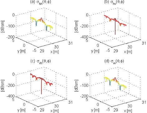
Fig. 7. Radar cross section of flat plate in (a)σhh; (b)σhv; (c)σvh and (d)σvvpolarization.
Fig. 8. Radar cross section of dihedral corner reflector in (a)σhh; (b)σhv; (c)σvhand (d)σvvpolarization.
5.3 Trihedral
Trihedral corner reflectors are commonly used as calibration targets or as a reference point in radar remote sensing. In this paper, the square trihedral corner reflector is used to evaluate the polarimetric radar cross section and the simulation results are presented in Fig. 9. Despite the similar curves of simu-lation results, there are different maximum values between each polarisation as follows:−12.54 dBsm, −15.89 dBsm, −26.63 dBsm und−17.79 dBsm forσhh,σhv,σvhandσvvin Fig. 9a, b, c and d, respecktively.
Figure 10 presents the comparison of simulation results of flat plate (green line), dihedral (blue line) and trihedral (red line) corner reflector of each polarization. Because the radar backscatter cross section is in addition to the frequency
Fig. 9. Radar cross section of trihedral corner reflector in (a)σhh; (b)σhv; (c)σvhand (d)σvvpolarization.
Fig. 10. Radar cross section of flat plate (green), dihedral (blue) and trihedral (red) corner reflector in (a)σhh; (b)σhv; (c)σvhand (d)
σvvpolarization.
strongly dependent on the aspect angle, the simulation results were calculated by using the SAR geometry which poses dif-ferent directions for the incident and scattered waves. An im-portant point to note is that the difference between the scat-tering maxima of each target conforms with standard theory, thus confirming the validity of the calculations.
6 Conclusions
section under SAR geometry. In this paper, three scatter ob-jects, i.e., flat plate, dihedral and trihedral corner reflector, are used to demonstration the capability of the new approxima-tion. The findings indicate that the SAR geometry has a large effect on backscatter cross section, because of continuously angle change during the observation time. Further work will also include the development of improved simulation method and target modelling for a better accuracy radar cross section, in particular the simulation efficiency.
References
Lee, J. S. and Pottier, E.: Polarimetric Radar Imaging from Basics to Applications, CRC Press, Boca Raton, 2009.