Adv. Radio Sci., 8, 109–115, 2010 www.adv-radio-sci.net/8/109/2010/ doi:10.5194/ars-8-109-2010
© Author(s) 2010. CC Attribution 3.0 License.
Advances in
Radio Science
Signal processing for plane wave actuators
T. Corbach, M. Holters, and U. Z¨olzer
Helmut-Schmidt-University, University of the Federal Armed Forces Hamburg, Germany
Abstract. Plane wave actuators without an enclosure per se have a forward and backward radiation. The backward ra-diation is unwanted in many applications when a single di-rection radiation is desired. To avoid the disadvantages of an enclosure a system is proposed, which provides a high sup-pression of the unwanted backward radiation using a pair of plane wave actuators. This is achieved by adapted input sig-nal filters. The influences of the second plane wave actuator to the forward radiated signal are suppressed as well. Addi-tionally, the system also provides for- and backward radiation of different signals with a high suppression of the radiation directions crosstalk. The required power for the signal sup-pression depends on the physical damping of the plane wave actuators and the space in between. The first realized pro-totype is designed for flat panel dipole loudspeakers to deal with the mentioned problems in the acoustic domain. The fil-ter design and a calibration algorithm for any given pairs of dipole loudspeaker are explained. The good performance of the developed system is proven by measurement results with the prototype system.
1 Introduction
Directed radiation is wanted in many applications to lower the effect of interference or to concentrate the radiated in-tensity to the target area. Most point source actuators per se radiate omnidirectional, whereas actuators of nearly plane waves mainly radiate to the forward and backward. Approx-imating a plane wave actuator by a two-dimensional array of point sources achieves similar directivity including the back-ward radiation. The backback-ward radiation of both, plane wave actuators and its point source approximation, is unwanted in
Correspondence to: T. Corbach ([email protected])
many applications when a single direction radiation is de-sired. However, an additional enclosure effectively suppress-ing the backward radiation increases the size and hence low-ers the good structural integration properties. The first real-ized prototype is designed for electrostatic flat panel dipole loudspeakers to deal with the mentioned problems in the acoustic domain. This paper presents alternative approaches to achieve a one sided radiation, describes the theory of the developed novel approach, demonstrates a practical realiza-tion and shows the results achieved with a DSP-based proto-type.
2 Alternative approaches
Different approaches to suppress acoustical or electro-magnetic traveling waves are available. Regardless the phys-ical domain one cancellation method suppressing backward travelling wave is to use a 180◦phase delayed second wave. The destructive superposition leads to a cancellation.
To suppress the backward radiation of an electrostatic flat panel loudspeaker by active measures a second parallel sim-ilar panel is used. A 180◦phase delay and an additional de-lay according to the panel distance cancels out one radiation direction (Olson, 1973). This approach only grants the sup-pression of the backward radiation but does not take the in-fluences on the forward radiation into account. Due to the dipole character of both panels the forward radiation is in-evitably disturbed by the signal of the second panel.
110 T. Corbach et al.: Signal processing for plane wave actuators
filter 1
filter 2
radiation
suppression
loudspeaker
input signal
Fig. 1. Scheme of the proposed system with the desired radiation.
3 Functionality
In this section the theory and functionality of the single-sided radiation is explained first, followed by a short explanation of the mentioned stereo expansion. Unlike the alternative approaches the developed system is able to treat forward and backward radiation as independent channels with a low crosstalk.
The proposed system is based on a parallel double elec-trostatic dipole loudspeaker with a digital signal processing of the input signal. The desired digital filters are gained by transfer functions of the system which have to be determined. These transfer functions represent the behavior of every sin-gle subsystem which the system can be divided into. Once the subsystems are described and determined it is possible to compute the desired filter transfer functions as well as the fil-ter impulse responses in time domain (Corbach et al., 2009). 3.1 Subsystem transfer function
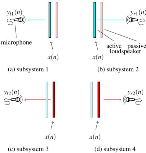
The system is divided into subsystems according to the ac-tive panels∈ {1,2} controlled by the discrete input signal x(n)and the occurring discrete output signalysk(n)at a ref-erence position at the observed radiation directionk∈ {l,r}. Due to the assumption of plane waves one reference position on axis is sufficient. For 2 panels and 2 possible radiation di-rections of the whole system, there is a total of 4 subsystems as depicted in Fig. 2.
To suppress the backward radiation of an electrostatic flat
panel loudspeaker by active measures a second parallel
sim-ilar panel is used. A 180
◦phase delay and an additional
de-lay according to the panel distance cancels out one radiation
direction Olson (1973). This approach only grants the
sup-pression of the backward radiation but does not take the
in-fluences on the forward radiation into account. Due to the
dipole character of both panels the forward radiation is
in-evitably disturbed by the signal of the second panel.
A further approach of suppressing the backward radiation
is the use of passive measures like an enclosure. But a high
degree of suppression with passive measures is achieved at
the cost of the structural integration properties of the
radia-tor. Furthermore, the enclosure itself causes reflections
dis-turbing the forward radiation. It has to be noted that these
reflections can be suppressed with the proposed approach as
well.
3
Functionality
In this section the theory and functionality of the single-sided
radiation is explained first, followed by a short explanation
of the mentioned stereo expansion. Unlike the alternative
approaches the developed system is able to treat forward
and backward radiation as independent channels with a low
crosstalk.
The proposed system is based on a parallel double
elec-trostatic dipole loudspeaker with a digital signal processing
of the input signal. The desired digital filters are gained by
transfer functions of the system which have to be determined.
These transfer functions represent the behavior of every
sin-gle subsystem which the system can be divided into. Once
the subsystems are described and determined it is possible to
compute the desired filter transfer functions as well as the
fil-ter impulse responses in time domain (Corbach et al., 2009).
3.1 Subsystem transfer function
The system is divided into subsystems according to the active
panel
s
∈ {
1
,
2
}
controlled by the discrete input signal
x(n)
and the occurring discrete output signal
y
sk(n)
at a reference
position at the observed radiation direction
k
∈ {
l
,
r
}
. Due
to the assumption of plane waves one reference position on
axis is sufficient. For 2 panels and 2 possible radiation
direc-tions of the whole system, there is a total of 4 subsystems as
depicted in Fig. 2.
In time domain the occurring output signals of the
subsys-tems are
y
l1(n) =
h
l1(n)
∗
x(n)
,
(1)
y
r1(n) =
h
r1(n)
∗
x(n)
,
(2)
y
l2(n) =
h
l2(n)
∗
x(n)
, and
(3)
y
r2(n) =
h
r2(n)
∗
x(n)
.
(4)
For example the impulse response
h
l1(n)
of subsystem 1
(Fig. 2a) describes all influences to the input signal
x(n)
radi-ated by loudspeaker 1 and the output signal
y
l1(n)
is observed
on the left side of the double dipole. The impulse response
h
r1(n)
(Fig. 2b) describes all influences to the input signal
x(n)
radiated by the same loudspeaker and the output signal
y
r1(n)
is observed on the opposite side of the double dipole.
All reflections and transmission through the passive and
ac-tive panels are included in the particular impulse response.
It has to be noted that this special case of a symmetric
con-figuration of similar panels leads to equal impulse responses
for the subsystems 1 and 4 (Fig. 2 (a) and (d)), as well as for
the subsystems 2 and 3 (Fig. 2 (b) and (c)). To keep the filter
computation general this simplification is not done here.
The subsystem transfer functions can be determined by
common measuring techniques like swept sine or noise
se-quences. Here the logarithmic swept sine technique (Farina,
2007) is used. The desired subsystem impulse responses are
defined by
h
l1(N
−
n) =
y
l1(n)
∗
x
−swp1(n)
,
(5)
h
r1(N
−
n) =
y
r1(n)
∗
x
−swp1(n)
,
(6)
h
l2(N
−
n) =
y
l2(n)
∗
x
−swp1(n)
, and
(7)
h
r2(N
−
n) =
y
r2(n)
∗
x
−swp1(n)
,
(8)
where
x
swp(n)
denotes the sweep test signal,
x
−swp1(n)
denotes
the inverse sweep and
y
s,k(n)
the measured sequence at the
observed side. The test signal
x
swp(n)
and its inverse
x
−swp1(n)
are both of length
N
.
As the measurements take place at just one point, the
func-tionality of the system is guaranteed in exactly this
measur-ing point. The high directivity and the low distance between
x(n)
yl1(n)
microphone
(a) subsystem 1
x(n)
yr1(n)
active passive loudspeaker
(b) subsystem 2
x(n)
yl2(n)
(c) subsystem 3
x(n)
yr2(n)
(d) subsystem 4
Fig. 2.Partition of the system into its subsystems (a) to (d)
accord-ing the actuated panel and the observed side of the system.
Fig. 2. Partition of the system into its subsystems (a) to (d)
accord-ing the actuated panel and the observed side of the system.
In time domain the occurring output signals of the subsys-tems are
yl1(n)=hl1(n)·x(n), (1) yr1(n)=hr1(n)·x(n), (2)
yl2(n)=hl2(n)·x(n), and (3)
yr2(n)=hr2(n)·x(n). (4)
For example the impulse response hl1(n) of subsystem 1 (Fig. 2a) describes all influences to the input signalx(n) ra-diated by loudspeaker 1 and the output signalyl1(n)is ob-served on the left side of the double dipole. The impulse re-sponsehr1(n)(Fig. 2b) describes all influences to the input signalx(n)radiated by the same loudspeaker and the output signalyr1(n)is observed on the opposite side of the double dipole. All reflections and transmission through the passive and active panels are included in the particular impulse re-sponse.
It has to be noted that this special case of a symmetric con-figuration of similar panels leads to equal impulse responses for the subsystems 1 and 4 (Fig. 2a and d), as well as for the subsystems 2 and 3 (Fig. 2b and c). To keep the filter computation general this simplification is not done here.
T. Corbach et al.: Signal processing for plane wave actuators 111 defined by
hl1(N−n)=yl1(n)·xswp−1(n), (5) hr1(N−n)=yr1(n)·xswp−1(n), (6) hl2(N−n)=yl2(n)·xswp−1(n), and (7) hr2(N−n)=yr2(n)·xswp−1(n), (8) wherexswp(n)denotes the sweep test signal,xswp−1(n)denotes the inverse sweep andys,k(n)the measured sequence at the observed side. The test signalxswp(n)and its inversexswp−1(n) are both of lengthN.
As the measurements take place at just one point, the func-tionality of the system is guaranteed in exactly this measur-ing point. The high directivity and the low distance between the panels enlarge the area of controlled radiation nearly to the full sphere.
3.2 Filter impulse response
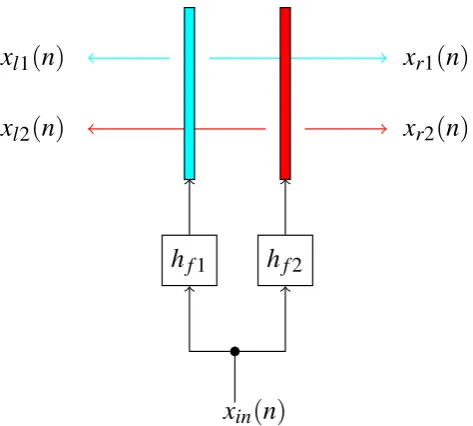
To determine the desired filter impulse responses the whole system is described by the subsystems’ impulse responses. This is achieved by expressing all appearing signal parts by the input signal, the desired filter impulse response, and the subsystems’ impulse responses. The signal part on the left side, created by input signalxin(n) convolved with the un-known filter impulse response hf1(n) and the impulse re-sponsehl1of subsystem 1, can be denoted by
xl1(n)=hl1(n)·hf1(n)·xin(n)
| {z }
x1(n)
. (9)
Similarly, the other signal parts on both radiation sides of the double dipole loudspeaker can be denoted by
xr1(n)=hr1(n)·hf1(n)·xin(n)
| {z }
x1(n)
, (10)
xl2(n)=hl2(n)·hf2(n)·xin(n)
| {z }
x2(n)
and (11)
xr2(n)=hr2(n)·hf2(n)·xin(n)
| {z }
x2(n)
. (12)
In the further equations the substitutions
x1(n)=hf1(n)·xin(n)and (13) x2(n)=hf2(n)·xin(n) (14) are done.
Figure 3 shows the whole system with its signal parts xl1(n),xr1(n),xl2(n)andxr2(n)of the different subsystems. To realize a single-sided radiation by the filtered excitation, the signal parts have to result in the behavior of a single panel xl1(n)+xl2(n)=hl1(n)·xin(n) (15) for the desired radiation side.
To achieve the suppression of the second, unwanted radi-ation direction the filtered excitradi-ation has to result in signal parts cancelling out each other. By equation this yields xr1(n)+xr2(n)=0 . (16) Inserting Eqs. (9) and (11) into Eq. (15), and Eqs. (10) and (12) into Eq. (16) results in the required equations to describe the desired radiation characteristic by the subsystems and its signal parts:
hl1(n)·x1(n)+hl2(n)·x2(n)=hl1(n)·xin(n) (17) hr1(n)·x1(n)+hr2(n)·x2(n) =0 . (18) The final computation of the filter impulse responseshf1(n) andhf2(n)is done in the frequency domain. Therefore the time signals of Eqs. (17) and (18) are transformed into fre-quency domain by the Fourier transform with adequate time domain zero padding:
Hl1(ej )X1(ej )+Hl2(ej )X2(ej )=Hl1(ej )Xin(ej )(19) Hr1(ej )X1(ej )+Hr2(ej )X2(ej )=0 . (20) The back substitutions in frequency domain
X1(ej )=Hf1(ej )Xin(ej )and (21) X2(ej )=Hf2(ej )Xin(ej ), (22) as well as solving the Eqs. (19) and (20) for the filter transfer functionsHf1(ej )andHf2(ej )gives
Hf1(ej )=
Hl1(ej )Hr2(ej )
Hl1(ej )Hr2(ej )−Hr1(ej )Hl2(ej )
and (23) Hf2(ej )=
−Hr1(ej ) Hr2(ej )
Hf1(ej ). (24)
Finally the inverse DFT is applied to the filter transfer func-tions to obtain the desired filter impulse responseshf1(n) andhf2(n):
Hf1(ej )s chf1(n) Hf2(ej )s chf2(n). (25)
3.3 Signal computation
h
f1h
f2x
l1(n)
x
l2(n)
x
r1(n)
x
r2(n)
x
in(n)
Fig. 3. Scheme of the entire system including all signal parts
radi-ated by the single panels.
3.4 Synthetic filter impulse response
To clarify the systems functionality a filter computation with the use of synthetic subsystem impulse responses is done. Therefore, the plane wave sources are assumed to be ideal and equal at a sample-distance ofd, and the wave transmis-sion through the source is assumed to have a frequency inde-pendent attenuation ofg.
Due to the symmetry this leads to equal impulse responses hd(n)=hl1(n)=hr2(n)=δ(n−dd) (28) for the subsystems 1 and 4, withdd representing the sam-ples needed from the source to the reference position. Since the subsystems 2 and 3 describe the transmission through a source to the reference point, adt-delayed and attenuated unit impulse yields their impulse response
ht(n)=hl2(n)=hr1(n)=g·δ(n−dt). (29) With direct delay ofdd=5, transmission delay ofdt=9, and an attenuation ofg=0.8 the subsystems are described by the impulse responseshd(n)andht(n)depicted in Figs. 4 and 5. The Fourier transform yields the subsystems’ transfer functionHl1(ej ),Hr2(ej ),Hl2(ej ), andHr1(ej ). The desired filter transfer functionsHf1(ej )andHf2(ej )are computed using Eqs. (23) and (24). The inverse Fourier transform then gives the desired filter impulse responses hf1(n)andhf2(n)depicted in Figs. 6 and 7. The sample-distance d between each impulse in the filter impulse re-sponse exactly amounts
d=dt−dd=9−5=4 , (30) hd
(
n
)
nin samples -1
0 1
0 10 20 30 40 50 60
Fig. 4. Synthetic impulse response of the sub systems 1 and 4.
ht
(
n
)
nin samples -1
0 1
0 10 20 30 40 50 60
Fig. 5. Synthetic impulse response of the sub systems 2 and 3.
hf
1
(
n
)
nin samples -1
0 1
0 10 20 30 40 50 60
Fig. 6. Computed impulse responsehf1(n).
hf
2
(
n
)
nin samples -1
0 1
0 10 20 30 40 50 60
T. Corbach et al.: Signal processing for plane wave actuators 113
x
l1(
n
)
x
l2(
n
)
x
r2(
n
)
x
r1(
n
)
Fig. 8. Signal parts of each loudspeaker after about 70 samples with
an unit impulse input signalxin(n)=δ(n).
and each impulse decreases by a factor ofg. This gains an equation for the filter impulse responses
hd(n)= N X
k=0
g2k·δ(n−d·2k) (31)
ht(n)= N X
k=0
g2k+1·δ (n−d (2k+1)). (32)
For this example the impulse response is cut after 64 samples. A closer look athf1(n)andhf2(n)explains the behavior of the system. Let us assume a single unit impulse as input sig-nalxin(n)=δ(n), which has to be radiated to the radiation di-rection. The first impulsehf1(0)=1 represents this desired radiation of the untouched signal to the radiation direction. The first impulse at the second radiatorhf2(d)=ggains the needed 180◦phase shifted, attenuated wave to suppress the unwanted backward radiation. Note, that there already is a 180◦phase shift between forward and backward radiated sig-nal of each source due to its dipole character. Since the sec-ond radiator itself has a backward radiation, too, a further, again attenuated impulsehf1(2d)=g2is needed to keep the desired radiation uninfluenced. The attenuation leads to an exponential decay of needed signal “echoes” to achieve the single sided radiation.
Figure 8 shows the signal parts of the sources after about 70 time steps. This shows the direct dependency of the addi-tionally needed power and the physical attenuation from the origin of the wave to origin of the 180◦phase shifted wave. 3.5 Stereo radiation
Besides the single-sided radiation this approach allows the radiation of independent signals to each direction. The sup-pression of the crosstalk between the directions is equal to the suppression of backward radiation of the single-sided ra-diation. The stereo radiation is easily achieved by applying the filter unit (hf1(n),hf2(n)) to both input signalsxin1(n) andxin2(n). The filter outputs are summed up by choosing different radiation directions for each filter unit as shown in
h
f1h
f2h
f1h
f2+
+
x
l1(
n
)
x
l2(
n
)
x
r1(
n
)
x
r2(
n
)
x
in1(
n
)
x
in2(
n
)
x
A(
n
)
x
B(
n
)
Fig. 9. Scheme of the system with dedicated signal processing for
every independent input signal summed up to stereo radiation.
Fig. 9. Now the sum of the output of filterhf1(n)driven by input signalxin1(n)and the output of filterhf2(n)driven by input signalxn2(n)has to actuate panel 1. Panel 2 has to be actuated by the sum of the output of filterhf1(n)driven by xin2(n)and output of filterhf2(n)driven byxin1(n). xA(n)=hf1(n)·xin1(n)+hf2(n)·xin2(n) (33) xB(n)=hf1(n)·xin2(n)+hf2(n)·xin1(n) (34) Certainly this causes higher restriction to the needed damp-ing factor to avoid clippdamp-ing (see Sect. 3.3).
4 Prototype system
| Hrad
(
f
)
|
in
dB
f in Hz
-6 -4 -2 0 2 4
200 1k 10k
Fig. 10. Difference of the compared frequency responses at the
radiation side between enabled and disabled signal processing.
5 Measurement results
The measurements are done on axis with microphones on both sides at the same distance of about 20 cm. Once again the exponential sine sweep method is applied to get the im-pulse responses and transfer functions of the entire system. The reflections of the walls at the measurement location are removed in the computed transfer functions by windowing its impulse responses.
The transfer functions of the entire system are measured twice for enabled and disabled signal processing. That means for the case of disabled signal processing the panel located to the radiation side is actuated, whereas the panel to the suppression side stays passive. The achieved differences be-tween enabled and disabled signal processing at both sides |Hrad(f )|and|Hsup(f )|are depicted in Figs. 10 and 11. The behavior on the radiation side of the double dipole with acti-vated signal processing was desired to have low differences to a single radiating dipole loudspeaker.
The measured result in Fig. 10 shows only minor differ-ences between the enabled and disabled signal processing of less than 4 dB. For most audio signals like speech or mu-sic the auditory impression approves nearly no perceivable differences when activating the signal processing.
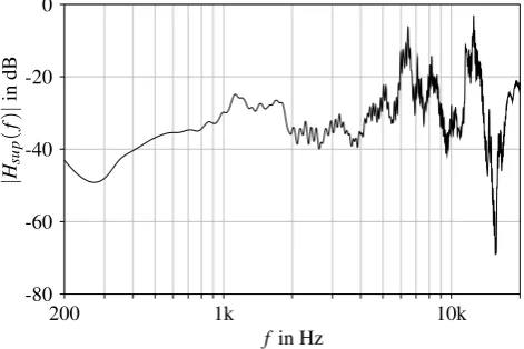
However, the second radiation direction was desired to be suppressed by the system to achieve a single-sided ra-diation by dipoles. Figure 11 shows the difference of the transfer function for disabled and enabled signal processing of the system. A high broadband active attenuation is ob-servable. For increased frequencies(>5 kHz)the attenua-tion values show higher fluctuaattenua-tions. Explanaattenua-tions for this behavior could be the used passive amplifiers providing the required bias voltage for the electrostatic panels. For higher frequencies the capacitive behavior of the panels causes a high current. The used combination of the passive adapter and a common hi-fi amplifier is not sufficient to provide ac-curate signals.
|
Hsu
p
(
f
)
|
in
dB
fin Hz
-80 -60 -40 -20 0
200 1k 10k
Fig. 11. Difference of the compared frequency responses at the
suppression side between enabled and disabled signal processing.
6 Discussion
A limitation of this approach is the additional power needed to suppress all occurring “echoes”. To avoid quantization clipping the filters have to be normalized. As countermeasure to the digital normalization a higher amplification is needed to get a similar effective output compared to single source radiation. This additional power needed directly depends on the attenuation of radiating through an actuator and requires amplification headroom of the sources for low attenuation values. The decay of the filter impulse response, hence the required filter length, depends on the attenuation as well. The attenuation through a typical actuator is usually sufficient in the audio domain, leading to reasonable ampflications and filter lengths.
In principle the proposed approach of controlling the ra-diation of plane wave actuators with forward and backward radiation should work independently of the physical domain of the wave. The advantages of this approach compared to passive methods have to be investigated separately for each physical domain. However, it makes use of the cancellation by destructive superposition of waves, hence it is applicable wherever sources of travelling waves radiate into 2 opposite directions.
7 Conclusion
T. Corbach et al.: Signal processing for plane wave actuators 115 radiation direction. This approach of suppressing the
sec-ond radiation direction of dipole loudspeakers is applicable wherever loudspeakers have to be integrated and no further passive efforts to suppress the backward radiation is wanted or possible.
According to this developed system further applications can be found beyond the single-sided radiation. For example the extension to a stereo radiation of different independent signals to both sides is already realized.
References
Panphonics Oy, Audio Element Manual v1.1, Panphonics, http: //www.panphonics.com/pdf/AudioElementManualv1-1.pdf, 2009.
Corbach, T., Holters, M., and Z¨olzer, U.: Flat loudspeaker radiation characteristics controlling method, involves compensating sound signals that are emitted from loudspeaker by phase shifted com-pensation signal in moment of passage via another loudspeaker, German Patent – DE102007049407A1, 2009.
Farina, A.: Advancements in impulse response measurements by sine sweeps, in: 122nd AES Convention, Vienna, Austria, 2007. Olson, H. F.: Gradient Loudspeakers, Journal of the AES, 21, 86–