ORIGINAL ARTICLE
Experimental Study on Wear Characteristics
of PCBN Tool with Variable Chamfered Edge
Tao Chen
*, Lixing Song, Suyan Li and Xianli Liu
Abstract
Owing to heavy dynamic and thermal loads, PCBN tools are seriously worn during hard cutting, which largely con-strains the improvement of their machining performance. Therein, the chamfered structure of a cutting edge has a notable influence on the tool wear. Thus, a comparative study was carried out on the wear morphology and wear mechanism of PCBN tools with either a variable chamfered edge or an invariable chamfered edge. The results indicate that, for a PCBN tool with a variable chamfered edge, the rake wear area is far from the cutting edge and slowly extends toward it. A shallow large-area crater wear occurs on the rake face, and the flank wear area has a long trian-gular shape with a smaller wear area and width, and the cutting edge remains in a good state during the cutting pro-cess. In contrast, for a PCBN tool with an invariable chamfered edge, a deep small-area crater appears on the rake face, and the wear area is close to the cutting edge and quickly extends toward it. Thus, it is easy for chips to accumulate in the crater, resulting in large-area and high-speed wear on the flank face. In addition, the tool shows a weak wear resistance. In the initial wear stage, the rake wear mechanism of the two cutting tools is a mixture of abrasive, oxida-tion, and other types of wear, whereas their flank wear mechanism is dominated by abrasive wear. With an aggrava-tion of the tool wear, the oxidaaggrava-tion and diffusion wear mechanism are both increasingly strengthened. The rake wear of the cutter with a variable chamfered edge showed an obvious increase in the oxidation and diffusion wear, as did the flank wear of the cutter with an invariable chamfered edge. This study revealed the wear mechanism of the PCBN tool with a variable chamfered edge and provided theoretical and technological support for its popularization and application in the machining of high-hardness materials.
Keywords: Hard cutting, Variable chamfered edge, PCBN tool, Wear morphology, Wear mechanism
© The Author(s) 2019. This article is distributed under the terms of the Creative Commons Attribution 4.0 International License (http://creat iveco mmons .org/licen ses/by/4.0/), which permits unrestricted use, distribution, and reproduction in any medium, provided you give appropriate credit to the original author(s) and the source, provide a link to the Creative Commons license, and indicate if changes were made.
1 Introduction
Characterized by a high hardness, strength, and fragil-ity, but a poor thermal conductivfragil-ity, hardened steel is typically regarded as a difficult-to-machine material [1], and its finish cutting is usually conducted using PCBN tools. During the machining hardening of steel, heavier mechanical and thermal loads occur in the cutting area [2, 3], and thus at high temperature and high pressure, the tool-workpiece and tool-chip friction become severe, resulting in quick rake and flank wear. In particular, when the tool wear develops beyond a certain extent, the cut-ting force and cutcut-ting temperature clearly increase and vibrations will even occur [4–7], which will cause further
breakdowns such as chipping, fragmenting, rupturing, and peeling. This has a serious impact on the machining surface quality, and improvements of the hard machining performance plateau.
Scholars both at home and abroad have carried out numerous related studies on PCBN tool wear. Chou et al. [8] researched the effects of the CBN content on the tool wear during hard machining, and concluded that a tool with a low CBN content has a relatively smaller wear rate than a tool with a high CBN content, and its machin-ing surface quality is more satisfactory. Zhou et al. [9] conducted an experimental study on the machining of hardened steel 100Cr6 using a PCBN tool, and deter-mined the effects of the chamfer angles on the tool wear. Based on an experiment on the cutting of hardened steel AISI4340, Coelho et al. [10] studied the influence of the coating types on the PCBN tool wear, and found that
Open Access
*Correspondence: [email protected]
a TiAlN nano coating cutting tool is the least worn, a tool coated with TiAlN is less worn, a tool coated with AlCrN is more worn, and an uncoated tool is the most worn. Arsecularatne et al. [11] studied the effects of the cutting parameters on the tool wear in the machining of hardened steel AISI D2 using a PCBN tool, and pro-posed optimum cutting parameters aiming at the tool life and volume of the material removal. Poulachon et al. [12] investigated the influence laws of the PCBN tool wear morphology, based on different hardened steels, and revealed that the tool flank grooves have a correla-tion with the microstructure of these steels. Zhao et al. [13] focused on the surface roughness evaluation dur-ing hard turndur-ing and found that the cuttdur-ing-edge radius of the PCBN tool has a significant influence on the sur-face roughness and tool wear. Das et al. [14] carried out an experiment on the hard turning of AISI 4140 steel using ceramic tools coated with PVD-TiN and revealed that the surface roughness is mainly influenced by the feed and cutting speed. Anmark et al. [15] researched the fine machining of carburizing steel using PCBN tools, and determined the correlation between the tool wear mechanism and the inclusion components in the work-piece materials. Ramanuj et al. [16] compared the wear characteristics in the hard turning of AISI D2 steel using a coated carbide cutter and a ceramic cutter individu-ally, and found that the wear mechanisms of the coated carbide tool are mainly abrasion, diffusion, and notching wear, whereas the ceramic tool showed a good stability without a catastrophic failure. Mahfoudi et al. [17] inves-tigated the tool wear that occurs when the PCBN tool is used to machine harden steel AISI 52100 at a high speed, and established a crater wear prediction model based on the temperature distribution in the tool-chip contact area. In addition, Huang et al. [18] built a model for pre-dicting the rake crater wear depth of a PCBN tool, and verified its accuracy experimentally, during which the PCBN tool was used to cut hardened steel AISI 52100. Combining FEA with the cutting experiments, Özel et al. [19, 20] conducted comparative research into the wear morphology and wear process of two different PCBN tools with a variable rounded edge and an invari-able chamfered edge. In addition, other researchers have focused on the tool wear mechanisms, such as abrasive wear, bond wear, diffusion wear, and chemical wear, dur-ing hard turndur-ing [21–24].
In conclusion, the current study on tool wear during hard turning focuses on PCBN tools with an invariable chamfered edge. In comparison, a tool with a variable cutting edge can form a spatially curved edge and there-fore improve the thermolysis of the chip removal and tool life, reducing the cutting resistance. Such merits have drawn the attention from concerned scholars, and have
been preliminary explored regarding tool fabrication techniques [25–27] and the cutting performance [28–30]. A PCBN tool with a variable chamfered edge was stud-ied, and research into its wear morphology and mecha-nism was carried out based on a high-speed hard turning experiment.
2 Structural Characteristics of PCBN Tool with Variable Chamfered Edge
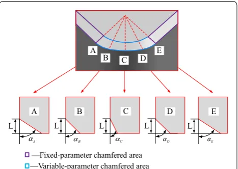
A PCBN tool with a variable chamfered edge and such a tool with an invariable chamfered edge differ in their chamfered structures. The chamfered structure of the latter has a fixed width and angle, whereas that of the former consists of a fixed-parameter area and a variable-parameter area. The fixed-variable-parameter area, whose cham-fer width and angle are both fixed, starts at the linear edge and extends toward the rake face, whereas the vari-able-parameter area begins from the curved edge, and its chamfer width is fixed, but its chamfer angle is variable, as shown in Figure 1.
To further illustrate the structural characteristics of a variable chamfered edge, five cross-sections were extracted, namely, A, B, C, D, and E. In Figure 1, the value of chamfer width L was fixed, and the chamfer angle αi
was variable and varied linearly along the corner radius, forming only two symmetrical reverse spiral edge lines. The chamfer width was 0.15 mm, the minimum chamfer angle was − 15°, and the maximum angle was − 30°.
3 Experimental Scheme
A corresponding high-speed hard turning experiment was designed in this study to investigate the wear mor-phology and wear mechanism of the cutting tool with a variable chamfered edge. The experiment was conducted on a numerically controlled lathe CK6150, in which a
—Fixed-parameter chamfered area —Variable-parameter chamfered area
L A
A
α
B L
B α
L
C α
L E
D α
D L
E α C
A
B C D E
GCr15 bearing outer ring with a hardness of 60 ± 2 HRC served as the workpiece, and its outer diameter was 62 mm, its width was 17 mm, and its major chemical composition was as shown in Table 1. Self-made PCBN tools with a variable chamfered edge and an invari-able chamfered edge were both used in the experiment. The two tools shared the same specifications, namely, CNGA1204. Specifically, the granularity was 1.5 μm, the CBN content was 50%, the invariable chamfer parameter was 0.15 mm × 30°, the corner radius was 0.8 mm, the tool shank was a DCLNR 2525M12, and after the cutting tool was set, the rake angle was − 6°, the clearance angle was 6°, the cutting edge angle was 95°, and the minor ting edge angle was 5°. The experimental system and cut-ting tools are as shown in Figure 2.
During the experiment, the fixed cutting parame-ters were as follows. The cutting speed was 150 m/min, the cutting depth was 0.1 mm, and the feed rate was 0.2 mm/r. A PCBN tool with a variable chamfered edge and a tool with an invariable chamfered edge were suc-cessively used in the cutting experiment. For every 20 feeds, the workpiece and chips were kept for a subsequent
testing of the surface quality and chip micromorphology; in addition, an extended depth field microscope (VHX-1000) and an electronic scanning microscope (FEI, Sirion 200) were used to test the tool wear, and the cutting forces were measured using a piezoelectric dynamom-eter (Kistler, 9257B) until the blade damage ended the experiment.
4 Experimental Results and Analysis 4.1 Wear Morphology of Cutting Tool
Figure 3 shows the rake and flank wear morphology of the two PCBN tools with different chamfered edges when the flank wear reached 0.1 mm. Figure 3(a) focuses on the tool with an invariable chamfered edge; its rake wear was crater-shaped and mainly concentrated on the chamfered surface, and the wear area was smaller. In contrast, Fig-ure 3(b) focuses on the tool with a variable chamfered edge, in which two crater wear zones occurred on its rake face, and the wear area was clearly large, namely, beyond the chamfered surface and extended to the rake face. Fig-ure 3(c) shows the flank wear zone of the tool with an invariable chamfered edge, which has a flat-arc, and the wear area was distributed evenly and almost indistinc-tively. In Figure 3(d), however, the wear zone of the tool with a variable chamfered edge was a long triangle and distributed in a relatively dispersive manner, in which the
Table 1 Major chemical composition of GCr15 (mass fraction, %)
Element C Mn Si Cr S P
Composition 0.95–1.05 0.20–0.40 0.15–0.35 1.30–1.65 < 0.020 < 0.027
Figure 2 Experimental system and PCBN tool
areas of both ends J and N were less worn, and the mid-dle area was more worn. In addition, the wear width b of the tool with a variable chamfered edge was larger than that of the tool with an invariable chamfered edge; none-theless, the wear area size of both tools showed a small difference.
To further analyze the change law of wear morphology of the two tools above as time passed, corresponding test indicators were needed to define the geometrical charac-teristics of the tool wear area. The rake crater wear had a significant influence on the cutting edge strength, which was evaluated by indicators such as the wear area S, wear depth KT, and distance from the crater wear bottom to the cutting edge L. Owing to the complexity of the cra-ter wear morphology, a white-light incra-terferomecra-ter was used to test the relative indicators. First, the crater wear area was scanned using the white-light interferometer, as shown in Figure 4(a). The related parameters were then extracted using a hole feature instrument, as shown in Figure 4(b). That is, the surface parameters included the crater wear area S, the maximum depth of which was the crater wear depth KT. Finally the sectioning function of the white-light interferometer was used to extract the crater wear section H, as shown in Figure 4(c), and the distance from the crater wear bottom to the cutting edge
L can be obtained from the section contour. The flank face is a key factor influencing the machined surface
quality, and thus the maximum wear width VBmax and wear depth b were chosen as indicators, and an extended depth of field microscope VHX-1000 was used to test them.
Figure 5 shows the change curves of the rake crater wear area and depth of the two cutting tools with dif-ferent chamfered edges as the cutting time continued. It can be seen from Figure 5 that the wear curves of the two cutting tools had a minor difference during the initial 4 min, but both the crater wear area and depth clearly increased as the cutting proceeded, and the cut-ting tools were quickly worn. When the cutcut-ting time passed 12 min, the wear areas of both cutting tools slowly increased and the wear depth grew explosively; their wear morphology is approximated herein. How-ever, when the cutting time passed 16 min, the wear morphology of both cutting tools began to clearly dif-fer. Namely, the wear area of the cutting tool with a variable chamfered edge increased to 92215 μm2 from 53469 μm2, which is a growth of 72.5%. At this point, the second crater wear zone occurred on the rake face, and its wear area was clearly larger than that of the cutting tool with an invariable chamfered edge, which resulted from the extension of the tool-chip contact area under the effect of the chip removal mechanism of the spiral cutting edge on the cutting tool with a vari-able chamfered edge. By further observing the wavy chip morphology formed during the cutting process, it
can be clearly found that, as the cutting proceeded, the contact length between the chips and rake face (namely, the distance between two peaks of the chips) increased gradually and bent, and as the contact area extended beyond the second crater zone in particular, the chips gradually broke.
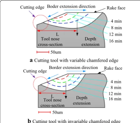
Figure 6 shows the extension of the crater wear cross-section H of the two tools with different cham-fered edges as the cutting time continued. It can be seen from Figure 6 that the crater wear began with the chamfered surface close to cutting edge, but as the cut-ting proceeded, the crater wear area extended gradually toward the two directions of the rake face and cutting edge, and the crater depth gradually increased. When the cutting time passed 16 min, the crater wear border of the tool with a variable chamfered edge extended toward the cutting edge by 34 μm and toward the rake face by 115 μm, whereas that of the tool with an invari-able chamfered edge extended toward the cutting edge by 70 μm and toward the rake face by 72 μm. At this moment, the crater wear area of the tool with a vari-able chamfered edge was already beyond the chamfered surface and extended toward the rake face, whereas that of the tool with an invariable chamfered edge was still concentrated at the chamfered surface. This proves that, for the tool with a variable chamfered edge, its wear area extended more slowly toward the cutting edge; in addition, the distance from the crater wear bot-tom to the cutting edge L was clearly larger than that of the tool with an invariable chamfered edge. Therefore, in comparison, the tool with a variable chamfered edge
has an ideal retentivity of the cutting edge, which helps prolong the tool life.
Figure 7 shows the change curves of the maximum flank wear width VBmax and flank wear length b of the two tools with different chamfered edges as the cut-ting time continued. It can be seen from Figure 7 that, as the cutting proceeded, the flank wear length b of the tool with a variable chamfered edge varied less and was approximately 1.2-times as long as that of the tool with an invariable chamfered edge. When the cutting time passed 12 min, the flank wear VBmax of the tool with a vari-able chamfered edge reached 52 μm, which is obviously smaller than that of the tool with an invariable chamfered edge, that is, approximately one half. Moreover, the sec-ond crater wear area of the tool with a variable chamfered edge exerted a smaller impact on the flank wear VBmax; in addition, it grew approximately linearly, but clearly more slowly than that of the tool with an invariable chamfered edge. When the cutting time reached 32 min, the cutting edge of the tool with a variable chamfered edge showed an obvious chipping, and meanwhile the corresponding workpiece surface morphology was clearly deteriorated, whereas that of the tool with invariable chamfered edge was already broken when cutting for 24 min.
4.2 Analysis of Tool Wear Mechanism
Figure 8(a) and (b) show the wear morphology of the tool with a variable chamfered edge when the flank wear was 52 μm, whereas Figure 8(c) and (d) show the wear mor-phology of the tool with an invariable chamfered edge when the flank wear was 55 μm. For an analysis of the wear mechanism of the tool with a variable chamfered edge, a scanning electron microscope with an inbuilt EDS was used to analyze the changes in energy spectrum
Boder extension direction
Cutting edge Rake face
Depth extension Tool nose cross-section 50um 4 min 8 min L 12 min 16 min
a Cutting tool with variable chamfered edge
Tool nose cross-section
Depth extension Border extension direction
Cutting edge Rake face
50um L 4 min 8 min 12 min 16 min
b Cutting tool with invariable chamfered edge
Figure 6 Extension of crater wear cross-section H of the two different tools
4 12 20 28 36
250 200 150 100 50 Maximu mw ear width VB ma x (μ m)
Cutting timeT(min)
We ar leng th b (μ m) 900 180 360 540 720 chipping 0 2.0 1.0 0 um um 4.0 2.0 0 ④ ③ ② ①
①—Wear length of cutting tool with variable chamfered edge
②—Wear length of cutting tool with invariable chamfered edge
③—Maximum wear width of cutting tool with invariable chamfered edge
④—Maximum wear width of cutting tool with variable chamfered edge
of all elements to find the reasons for the tool wear. Thus, four test points were chosen in different wear areas of the rake face, namely, point I at the brim of the cutting edge, points II and IV at the crater bottom, and point III at the border of the crater wear area, as shown in Figure 8(a). In the same way, three test points were chosen in differ-ent wear areas of the flank face, that is, VI in the mid-dle, and V and VII at both ends, as shown in Figure 8(b). In addition, in the corresponding rake and flank wear areas of the tool with an invariable chamfered edge, three test points were also chosen, namely, VIII, IX, and X, as shown in Figure 8(c) and (d).
4.2.1 Analysis of Rake Wear Mechanism
Figure 9 shows the element composition of all test points on the rake face of the tool with a variable chamfered edge. It can be seen that the elements Fe, O, and C were added in the crater wear, of which the elements Fe and C were from the workpiece, whereas element O was from the outer environment. Considering the existence of the elements above, it can be judged initially that the oxida-tion wear and diffusion wear both occurred in the wear area. Through a further comparison of the element con-tent of all points I, II, III, and IV, it can be seen that the content of Fe and O at point II of the crater wear bot-tom was the highest, and was clearly higher than that at point IV, which indicates the above-mentioned for-mation sequence of the two wear areas. Meanwhile, the O content was apparently higher than the Fe content, which indicates that O reacted with Fe, forming the
corresponding oxides, or even reacted in a complicated manner with the other elements. Compared with point VIII, the contents of Al and Ti at point I were higher, whereas those of Fe and Si were lower and approximated the tool matrix element content, which showed that the cutting edge wear of the tool with a variable cham-fered edge was minor and that the cutting edge was well protected. Compared with point IX of the tool with an invariable chamfered edge, the higher O content of point IV at the crater wear bottom of the tool with a variable chamfered edge indicated that the oxidation and diffu-sion wear mechanism in the rake wear of the tool with a variable chamfered edge had clearly a higher proportion than the tool with an invariable chamfered edge.
4.2.2 Analysis of Flank Wear Mechanism
It can be easily seen from Figure 8(b) that a large num-ber of long groove-shaped dents occurred on the flank wear face because hard spots in the machined surface material exerted scraping and a grinding impact on the flank face, which wore the binder down, and as a result, CBN granules peeled off easily and formed grooves. Here, the abrasive wear occurred similarly to the wear mechanism of the tool with an invariable chamfered edge. Through the energy spectrum analysis of points V, VI, and VII, it was found that only a few Fe, O, and Si elements existed at the above three points, whereas more Al and Ti elements were shown from the binder. Nonetheless, no obvious oxidation and diffusion wear occurred, and here the abrasive wear was still the main factor. The contents of all elements at point VI were further tracked, and the variation with the maximum
Figure 8 SEM morphology of two tools with different chamfered edges
a Element analysis of two tools with different chamfered edges
bElement analysis in the rank wear area of the tool with variable chamfered edge
Fe O
Point IV
Ti Al Si
Cr V
1.0 2.0 3.0 4.0 5.0 6.0 7.0 Energy-keV
Fe O
Point IX
Ti Si Al
1.0 2.0 3.0 4.0 5.0 6.0 7.0 8.0 Energy-keV
50 40 30 20 10
Point I Point III Point IV
Al Ti
Fe Si O Others
Wt/%
Point II
wear width VBmax was analyzed, as shown in Figure 10. With an increase in VBmax, the contents of Fe, O, and Si increased, whereas those of Al and Ti decreased, which indicated that the proportion of oxidation and diffusion wear increased. By comparing the contents of the elements at test points VI and X, when VBmax was 0.05 mm, it was shown that the flank oxidation and dif-fusion wear of the tool with a variable chamfered edge had a smaller proportion than the tool with an invari-able chamfered edge. By comparing the contents of the elements at test points V, VI, and VII in the flank wear area of the tool with a variable chamfered edge, it was found that the contents of O, Fe, and Si at point VI were evidently higher than those at points V and VII, which showed that the oxidation and diffusion wear at the middle point VI were more serious than those at both end areas. This is because, during the cutting process, the cutting load concentration and poor thermolysis in area M resulted in an accumulation of the cutting temperature. Consequently, the oxidation and diffusion wear were aggravated, and the cutting-edge strength decreased, which also partly explain why the wear pro-portion of area M was higher than that of areas J and N.
4.3 Analysis of the Effect of Tool Wear on Cutting Force Figure 11 shows the varying curves of the cutting forces of the two tools with different chamfered edges dur-ing the wear process. It can be seen from Figure 11
that, with the aggravation of the tool wear, all cutting forces of the two cutting tools varied almost identically, i.e., all cutting forces gradually increased, namely, the radial force Fy clearly varied, whereas the axial force Fx and tangential force Fz slightly increased. In addition,
Fy and Fx of the tool with a variable chamfered edge were both minor to those of the tool with an invariable chamfered edge because the flank wear of the former was slighter than that of the latter, while Fz was bigger for the tool with a variable chamfered edge than that of the tool with an invariable chamfered edge because the spiral edge line of the tool with a variable chamfered edge increased the contact area between the tool and workpiece, and when moving along the feed direction the tool bore increased the cutting load. As the cut-ting proceeded, during the occurrence of the second crater wear, all cutting forces of the tool with a variable chamfered edge decreased, and here obvious troughs appeared, which is attributed to the fact that the for-mation of the second crater wear area increased the chip-breaking area, and thus the chips were more easily removed. As a result, all cutting forces decreased.
a Element analysis of two tools with different chamfered edges
50 40 30 20 10
Point VI Point VII
Al Ti
Fe Si O Others
Wt/%
Point V
b Element analysis in the flank wear area of the tool with variable chamfered edge
50 60 70 80 90
40 30 20 10 O,F e,S ic on tent Wt (% )
Maximum wear widthVBmax (µm)
Al,Ti conten t Wt (% ) 15 30 45 60 100 O Fe Si Al Ti
0 0
cElements analysis in the flank wear area of the tool with variable chamfered edge under different wear conditions
Fe O Point VI
Ti Si Al
1.0 2.0 3.0 4.0 5.0 6.0 7.0 8.0
Energy-keV
Fe O Point X
Si Ti Al V
1.0 2.0 3.0 4.0 5.0 6.0 7.0 8.0
Energy-keV
Figure 10 Element analysis of the flank wear area
3 9 15 21 27
280 230 180 130 30 Cut ting forc e F (N )
Cutting timeT(min) 33 39 80 Valley ① ② ③ ④ ⑤ ⑥
①üRadial force Fyof the tool with invariable chamfered edge
②üRadial force Fyof the tool with variable chamfered edge
③üTangential force Fzof the tool with variable chamfered edge
④üTangential force Fzof the tool with invariable chamfered edge
ĻüAxial force Fx of the tool with invariable chamfered edge
5 Conclusions
Based on a comparative cutting experiment of two PCBN tools, one with a variable chamfered edge and the other with an invariable chamfered edge, a study on the tool wear morphology and wear mechanism was carried out, and the effect of the tool wear on the cutting forces was analyzed. Thus, the following conclusions were drawn.
1. The variable chamfered structure improves the abil-ity of the PCBN tool to remove the chips. A shallow large-area crater wear forms on the rake face and is far from the cutting edge, whereas a long triangular wear occurs on the flank face and is not a large or wide area.
2. The rake wear of the two cutting tools begins with a chamfered face at the cutting edge, and gradually extends toward both the rake face and cutting edge with an aggravation of the tool wear. In contrast to the cutter with an invariable chamfered edge, the cut-ter with a variable chamfered edge extends its rake wear slowly toward the cutting edge, but quickly toward the rake face, which demonstrates a better cutting edge maintenance.
3. The cutter with a variable chamfered edge clearly shows more oxidation and a greater diffusion wear mechanism on its rake face than the cutter with an invariable chamfered edge, which is particularly obvi-ous in the first crater wear area. Its flank wear mech-anism is mainly abrasive wear, and it becomes more complicated with an aggravation of the tool wear, including many wear mechanisms, such as oxidation wear, and diffusion wear.
4. The variable chamfered structure forms a helical cut-ting edge, which is helpful in partially decomposing the radial and axial cutting forces, and effectively improves the stressed conditions of the cutting edge. Even under a state of serious wear, all cutting forces increase more slowly than a cutter with an invaria-ble chamfered edge, and thus a cutter with a variainvaria-ble chamfered edge possesses a better cutting perfor-mance.
Authors’ Contributions
TC was in charge of the whole trial; TC and LS wrote the manuscript; SL and XL assisted with sample preparation and experimental analysis. All authors read and approved the final manuscript.
Authors’ Information
Tao Chen, born in 1979, is currently a professor at Harbin University of Science and Technology, China. He received his PhD degree from Harbin University of Science and Technology, China, in 2009. His research interests include high-speed hard machining and high-high-speed cutting tools.
Lixing Song, born in 1995, is a MS candidate at Harbin University of Science and Technology, China. He works on tool wear study.
Suyan Li, born in 1972, is a PhD candidate at Harbin University of Science and Technology, China. Her research interests include the design of cutting tool and its optimization.
Xianli Liu, born in 1961, is currently a professor and a PhD supervisor at Harbin University of Science and Technology, China. His main research interests include high efficiency cutting and cutting tool technology.
Competing Interests
The authors declare that they have no competing interests.
Funding
Supported by National Natural Science Foundation of China (Grant No. 51475125), and Heilongjiang Provincial Natural Science Foundation of China (Grant No. E2016047).
Received: 10 September 2018 Accepted: 8 April 2019
References
[1] S Chinchanikar, S K Choudhury. Machining of hardened steel: Experi-mental investigations, performance modeling and cooling techniques: A review. International Journal of Machine Tools and Manufacture, 2015, 89: 95–109.
[2] G Bartarya, S K Choudhury. State of the art in hard turning. International Journal of Machine Tools and Manufacture, 2012, 52: 1–14.
[3] C S Kumar, S K Patel. Application of surface modification techniques dur-ing hard turndur-ing: Present work and future prospects. International Journal of Refractory Metals and Hard Material, 2018, 76: 112–127.
[4] M Dogra, V S Sharma, A Sachdeva, et al. Tool wear, chip formation and workpiece surface issues in CBN hard turning: A review. International Journal of Precision Engineering and Manufacturing, 2010, 11(2): 341–358. [5] S Saini, I S Ahuja, V S Sharma. Residual stresses, surface roughness, and
tool wear in hard turning: A comprehensive review. Materials and Manu-facturing Processes, 2012, 27(6): 583–598.
[6] O Gutnichenko, V Bushlya, J M Zhou, et al. tool wear and vibrations generated when turning high-chromium white cast iron with pcbn tools. Procedia CIRP, 2016, 46: 285–289.
[7] F Klocke, H Kratz. Advanced tool edge geometry for high precision hard turning. CIRP Annals-Manufacturing Technology, 2005, 54(1): 47–50. [8] Y K Chou, C J Evans, M M Barash. Experimental investigation on CBN
turn-ing of hardened AISI 52100 steel. Journal of Materials Processing Technol-ogy, 2002, 124(3): 274–283.
[9] J M Zhou, H Walter, M Andersson, et al. Effect of chamfer angle on wear of PCBN cutting tool. International Journal of Machine Tools and Manufacture, 2003, 43(3): 301–305.
[10] R T Coelho, E G Ng, M A Elbestawi. Tool wear when turning hardened AISI 4340 with coated PCBN tools using finishing cutting conditions. Interna-tional Journal of Machine Tools and Manufacture, 2007, 47(2): 263–272. [11] J A Arsecularatne, L C Zhang, C Montross, et al. On machining of
hardened AISI D2 steel with PCBN tools. Journal of Materials Processing Technology, 2006, 171(2): 244–252.
[12] G Poulachon, B P Bandyopadhyay, I S Jawahir, et al. The influence of the microstructure of hardened tool steel workpiece on the wear of PCBN cutting tools. International Journal of Machine Tools and Manufacture, 2003, 43(2): 139–144.
[13] T Zhao, J M Zhou, V Bushlya, et al. Effect of cutting edge radius on surface roughness and tool wear in hard turning of AISI 52100 steel. Interna-tional Journal of Advanced Manufacturing Technology, 2017, 91(9–12): 3611–3618.
[14] S R Das, D Dhupal, A Kumar. Study of surface roughness and flank wear in hard turning of AISI 4140 steel with coated ceramic inserts. Journal of Mechanical Science and Technology, 2015, 29(10): 4329–4340.
[15] N Anmark, T Bjork, A Ganea, et al. The effect of inclusion composition on tool wear in hard part turning using PCBN cutting tool. Wear, 2015, 334–335: 13–22.
during hard turning. International Journal of Machining and Machinability of Materials, 2018, 20(4): 320–344.
[17] F Mahfoudi, G List, A Molinari, et al. High speed turning for hard material with PCBN inserts: tool wear analysis. International Journal of Machining and Machinability of Materials, 2008, 3(1/2): 62–79.
[18] Y Huang, T G Dawson. Tool crater wear depth modeling in CBN hard turn-ing. Wear, 2005, 258(9): 1455–1461.
[19] T Özel. Computational modelling of 3D turning: Influence of edge micro-geometry on forces, stresses, friction and tool wear in PCBN tooling. Journal of Materials Processing Technology, 2009, 209(11): 5167–5177. [20] T Özel, Y Karpat, A Srivastava. Hard turning with variable micro-geometry
PCBN tools. CIRP Annals-Manufacturing Technology, 2008, 57(1): 73–76. [21] J Angseryd, H O Andrén. An in-depth investigation of the cutting speed
impact on the degraded microstructure of worn PCBN cutting tools. Wear, 2011, 271(9–10): 2610–2618.
[22] K Katuku, A Koursaris, I Sigalas. Wear mechanisms of PCBN cutting tools when dry turning ASTM Grade 2 austetmpered ductile iron under finish-ing conditions. Wear, 2010, 268(1): 294–301.
[23] E Uhlmann, H Riemer, D Schroter, et al. Investigation of wear resistance of coated PCBN turning tools for hard machining. International Journal of Refractory Metals and Hard Materials, 2018, 72: 270–275.
[24] L H Tang, Y J Sun, B D Li, et al. Wear performance and mechanisms of PCBN tool in dry hard turning of AISI D2 hardened steel. Tribology Interna-tional, 2019, 132: 228–236.
[25] B Denkena, J Köhler, C VenturaInt. Grinding of PCBN cutting inserts. Inter-national Journal of Refractory Metals and Hard Materials, 2014, 42(1): 91–96. [26] C Ventura, J Köhler, B Denkena. Strategies for grinding of chamfers in
cut-ting inserts. Precision Engineering, 2014, 38: 749–758.
[27] T Chen, D Y Wang, S Y Li, et al. Manufacture and grinding accuracy detec-tion of pcbn tools with variable chamfer edge. Journal of Mechanical Engineering, 2018, 54(11): 214–221. (in Chinese)
[28] B Denkena, J Köhler, B Breidenstein, et al. Influence of the cutting edge preparation method on characteristics and performance of PVD coated carbide inserts in hard turning. Surface and Coatings Technology, 2014, 254: 447–454.
[29] C Venture, J Kohler, B Denkena. Influence of cutting edge geometry on tool wear performance in interrupted hard turning. Journal of Manufac-turing Processes, 2015, 19: 129–134.