International Journal of Engineering
J o u r n a l H o m e p a g e : w w w . i j e . i rAnalysis of the Impact of Managed Pressure Drilling Technology on Current Casing
Program Design Methods
Y. Xu, Zh. Guan*, Hu. Zhang, Ho. Zhang, K. Wei
Department of Petroleum Engineering, China University of Petroleum (East China), Qingdao, China
P A P E R I N F O
Paper history: Received 12 June 2013
Received in revised form 12 July 2013 Accepted in 22 August 2013
Keywords:
Managed Pressure Drilling Casing Program Design Impact Analysis
Multi-pressure System Formation
A B S T R A C T
This paper analyzed the characteristics of managed pressure drilling (MPD) technology and impact of wellhead back pressure on the wellbore annulus pressure profile, and found that the application of this technology provides situation for improvement in the current casing program design. Meanwhile, the equivalent density of drilling fluid in wellbore annulus needs to consider the impact of back pressure. On this basis, casing program design for top-down design approach and multi-pressure system formation in MPD are established. Comparing and analyzing the results of casing program design in MPD and conventional drilling, it can be concluded that for the top-down design method, each layer of casing can reachto a deeper depth. It can also reduce the casing level for the multi-pressure system formation using wellhead back pressure to make the wellbore annulus pressure profiles bend. Thus, it can cleverly pass through the complex formation which needs multi-layer intermediate casings in conventional drilling. In this condition, the well structure can be simplified.
doi:10.5829/idosi.ije.2014.27.04a.18
1. INTRODUCTION1
Managed Pressure Drilling technology (MPD) applies certain back pressure at the wellhead based on different conditions to achieve precise control of wellbore pressure and make it in the safe density window, so that implementing balanced drilling [1-5]. The MPD uses closed drilling fluid circulating system. When a connection or tripping is made, the pressure in well fluctuate. In order to maintain the stability of the pressure, we need to add back pressure at the wellhead [1, 6, 7]. With comparison to conventional drilling, the drilling fluid density in MPD is lower. Its annulus vertical pressure gradient is also less than conventional drilling [5, 8-12]. Moreover, the wellhead back pressure provides a non-gradient pressure. It leads to the MPD annulus pressure profile which is different with conventional drilling [8, 13-16]. Therefore, it would impact the casing level and running depth when designing the casing program. In fact, MPD through the use of low-density drilling fluid and wellhead back pressure maintain the stability of pressure in the
*Corresponding Author Email: [email protected] (Zhichuan
Guan)
wellbore which indirectly broadens the adjustable range of drilling fluid density. Thus, thereby it gives room for improvement to the current casing program design [8, 17-19].
Current casing program design methods [20] are top-down, bottom-up, from middle to sides, and so on, which do not take to account the wellhead back pressure into influence on the equivalent density curve. Therefore, these are not entirely suitable for MPD casing program design. Through investigation and research, the current MPD technology does not form a new casing program design methods. If the current casing program design method is applied directly, it cannot be only out of touch with the scene actual, but also will result in unnecessary waste or even losses.
Therefore, it is necessary to study the changes of wellbore annulus equivalent density curves under managed pressure conditions. By calculating the well structure under different managed pressure conditions, different design methods, and different formation conditions, we analyze the impact of MPD technology on current casing program design methods. Thus, thereby we provide guidance for establishing new casing program design method which is suitable for MPD.
2. MATERIAL AND METHODS
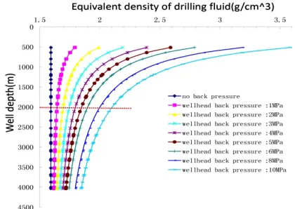
2. 1. The Influence of Wellhead Back Pressure on Annulus Pressure Profiles In MPD, the wellhead back pressure provides annulus pressure, a non-gradient pressure, which can certainly cause changes in the annulus pressure profile. In order to study the impact of wellhead back pressure, we calculated wellbore annulus equivalent density curves with different wellhead back pressure, shown in Figures 1 and 2. Since the upper data points have larger span, and have no practical significance for the study and also in order to show more conveniently, we remove the data points above 500 m.
As can be seen from the mentioned two graphs, the impact of wellhead back pressure on wellbore annulus pressure distribution is relatively significant. In shallow formations, the variation rate of equivalent density of drilling fluid is significantly increased with a decrease in depth. However, below 2000m, the equivalent density curves with different wellhead back pressure are close to straight lines. Thus, we can ignore the influence of depth. As a result, the wellhead back pressure changes can cause drilling fluid equivalent density curve translation. This shows that, during the MPD casing program design, wellhead back pressure must be considered into the equivalent density. We must also consider the wellbore annulus pressure profile bending situations.
2. 2. Constraint Conditions for Safe Open Hole Section in MPD we can see in MPD which wellhead exerted certain back pressure, the equivalent density of drilling fluid in wellbore annulus needs to consider the impact of back pressure. Therefore, the constraint conditions for safe open hole section in MPD need to be amended. Considering the impact of wellhead back pressure, drilling fluid density in MPD is required to meet the following criteria:
Anti-collapse and BOP:
(
)
{
max max}
( ) max ,
Em Hi p Sb c
r ³ r + + Dr r (1)
Ensure that the drilling fluid density can hold down formation to prevent the occurrence of kick and collapse.
Sticking prevention:
(
rE m (Hi)-rpm in)
´Hpm in´0 .0 09 8 1£ DP (2)Ensure that the differential pressure of drilling fluid density and the minimum formation pore pressure coefficient is less than differential pressure sticking margin.
Leak proof:
min ( )
Em Hi Sg Sf f
r + + £r (3)
Figure 1. Well depth 1000m, drilling fluid density 1.2, applying different back pressure, equivalent density curve
Figure 2. Well depth 4000m, drilling fluid density 1.6, applying different back pressure, equivalent density curve
Ensure that the drilling fluid density is not too large to prevent the formation pressure leakage.
Leak proof when shut-in:
1 1
( ) i ( )
Em i f k f n
n
H
H S S H
H
r r
-+ + ´ £ (4)
When shut-in, ensure that the drilling fluid density in the depth of the upper level casing shoe is not too large to prevent the formation pressure leakage.
Plus:
( ) BP
Em i m
i P H
gH
r =r + (5)
coefficient; rEm(Hi)is equivalent density of drilling
fluid;
r
pmaxis the maximum formation pore pressure coefficient of the calculation point and above; rcmaxis the maximum hole stability coefficient of the calculation point and above; rpminis the minimum formation pore pressure coefficient of the calculation point and above; DP is differential pressure sticking margin; Sf is security added value of formation fracture pressure; Dris the added value of the drilling fluid density; rfminis the minimum formation fracture pressure coefficient of the calculation point and above;min
p
H is the depth of minimum formation pore pressure;
1
-n
H is depth of the casing shoe of the up one level casing.
2. 3. Method for Determining the Structure and Setting Depth of Casing in MPD
2. 3. 1. The Casing Program Design Method of Top-down Model in MPD The equivalent circulating density of drilling fluid in MPD only need to suppress the formation which means equal to the pore pressure. However, conventional methods need to have some safety margin. This feature of the MPD technology will make the casing setting depth of each section deeper than the conventional drilling process. For some special formation, adopting the MPD method maybe reduce one layer of casing. This will make up for the shortcomings that the top-down method costs higher than the bottom-up method.
The steps of casing program method in MPD:
(1) Determining the setting depth of the surface casing H0; can refer to the traditional design methods and base on geological data for calculations. Currently, the top-down approach has not surface casing depth calculation methods. It generally relies on regional drilling experience. Specifically, the setting depth of surface casing should meet requirements such as the safety of well control and sealing the shallow aquifers, loose strata, gravel layers and so on. Finally, it should take a certain depth into the solid rock formation. (2) Determining the safe density window of the depth of upper level casing shoe, and use minimum value of safe density window as the initial valuer0 . (3) In steps of 1 meter, start fromH0, continue putting into the constrain Equations (5)-(9) for judgment until it cannot meet the constraint condition, then record the depth H1m (m=0);
(4) In steps of 0.01 g/ cm3 , increase the density of
drilling fluid to r1, then continue putting r1 into the
third step to get H1m (m=1) until rm become the maximum density window of the drilling fluid. At last, we get M numbers ofH1m , find the maximum as the
setting depth of the first intermediate casing;
(5) Then start fromH1, repeat steps 3 and 4, so that get the setting depth of the next casingH2;
(6) And so on, until we drill the destination layer. As can be seen from the design steps, the difference between the MPD method and conventional method is the calculation of equivalent density of drilling fluid. The MPD method considers well head back pressure. The circulation needs to be stopped in the operating process of pipe connection. During connection, the annulus drilling fluid density reduces the value of circulating pressure loss because of loop stops, while the wellhead back pressure makes compensation for the equivalent density of drilling fluid loss in the annulus. In the design calculations, we take 1 meter and 0.01
3
cm /
g as steps, and contrast the equivalent density of
drilling fluid with security open hole constraints. So, we can realize automatic well structure design by programming.
2. 3. 2. The Casing Program Design of Multi-pressure System Formation in MPD The multi-pressure system formation contains several sets of pressure systems in the same open hole. During the drilling process, the density of drilling fluid is determined by pressure profile such as pore pressure, fracture pressure and formation collapse pressure. Meanwhile, it must be adjusted according to the different lithology and different pressure systems in real time. When we drill low pressure region, especially in the lower strata which encountered a low pressure, due to the deeper depth, the drilling fluid density is difficult to ensure that the pressure of the drilling fluid column not only suppress the upper strata but also maintain a balance with fracturing gradient in the abnormal low pressure section at the same time. Thus, it easily leads to lost circulation and differential sticking and other underground complex issues which seriously impact on the safety and efficiency of drilling.
lower part of the borehole size will be greatly constraint and even by drilling, we cannot reach to the target layer so that end-of-life. Therefore, looking for a way to save the casing levels as well as safely drill though the abnormal low pressure formation is very necessary. Another characteristic of the MPD technology is using dynamic back pressure at the wellhead, the equivalent density curve of drilling fluid in the wellbore annulus bend (Figure 2). We can use this feature to find out the optimal value of the drilling fluid density and wellhead back pressure for certain multi-pressure system formation, which can achieve the purpose of only use one layer of casing to safely drill through the strata (For other strata, it may needs more than one layer casing, but we can minimize the casing layers using this design).
3. RESULTS AND DISCUSSION
3. 1. Comparative Analysis of Top-down Model Select a deep well in Heba block as the research object, then use the conventional top-down casing program design and the MPD condition method given in chapter 2.3.1 to design this well.
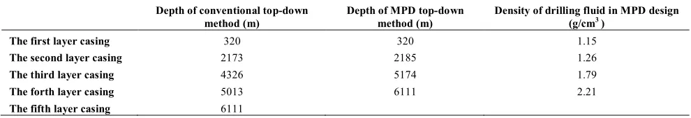
The formation specific design parameters are as follows: Design depth is 6100m, swabbing pressure coefficient is 0.05 g/cm3, security added value of formation fracture pressure is 0.06 g/cm3, surge pressure coefficient is 0.05 g/cm3, kick fair value is 0.06 g/cm3, normal pressure differential fair value is 13MPa, abnormal pressure differential fair value is 16MPa. The design results are shown in Figures 3a and 3b and Table 1.
As can be seen from the contrastive results: under MPD conditions, we can use lower density drilling fluid for drilling, and each layer can reach to the limit depth (the equivalent circulating density of drilling fluid is equal to the formation pore pressure). For the formation selected, only four casings are used to drill to the target depth safely, so a layer of casing can be saved compared with conventional methods. For the precise control of wellbore annulus pressure in MPD technology, when the equivalent density of drilling fluid is equal to formation pore pressure, it makes balanced pressure drilling, which can also help to protect the oil and gas reservoirs.
3. 2. Comparative Analysis of Multi-pressure System Formation Select a well which stratigraphic profile is shown in Figure 4 as the research object, respectively use the conventional top-down casing program design and the MPD multi-pressure system formation method given in chapter 2.3.2 to design this well.
Figure 3a. Conventional top-down casing program design results
Figure 3b. MPD design results
TABLE 1 Comparison results of casing program design
Depth of conventional top-down method (m)
Depth of MPD top-down method (m)
Density of drilling fluid in MPD design (g/cm3)
Figure 4. Fracture pressure and pore pressure profile of multi-pressure system formation
Figure 5. Comparison of equivalent drilling fluid density curve and formation pressure profile
Figure 6. Design processes of three points
Figure 7. MPD design in multi-pressure system formation
Figure 8. Conventional up-down method
MPD design: Through calculating annulus pressure distributions under different conditions of drilling fluid density and wellhead back pressure, we obtain a series of equivalent drilling fluid density curves. Take the drilling fluid density of 1.5 g/cm3 as an example (Figure 5). Identify the curve which can safely drill through the formation of multi-pressure system. Then, we can use the drilling fluid density
r
and wellhead back pressure0
BP
contrast with the stratigraphic profiles of the formation pore pressure and fracture pressure. We found that the equivalent density curve with 8MPa wellhead back pressure can safely cross the formation. Therefore, we can choose the drilling fluid density 1.5 g/cm3, wellhead back pressure 8MPa for managed pressure drilling to drill the multi-pressure system formation. It should be noted that different drilling fluid density corresponds to different curve distribution. We need to identify the best drilling fluid density (it’s 1.5 in this paper) by comparing, on this basis, find the best wellhead back pressure.
The casing program design can start from the lower strata of the multi-pressure system formation by bottom-up model. Put the equivalent density curve with 8Mpa wellhead back pressure into the formation pressure profile, so it meets with fracture pressure profile at the point A (Figure 6). Considering security added value of formation fracture pressure and surge pressure coefficient, A should move left a certain distance to B. Then, do vertical line through point B, it meets with equivalent density curve at the point C, so the depth of point C is depth of the upper layer casing shoe. Now, we can use the conventional bottom-up method to do the casing program design. Specific design results are shown in Figure 7:
As can be seen in Figure 7, the yellow line is the MPD equivalent density curve which can drill though the multi-pressure system formation safely. At about 2500m, the equivalent drilling fluid density curve and the pore pressure profile is tangent. When making a connection or other operations, we can calculate the required wellhead back pressure value by MPD design method for the narrow density window formation [21]. Thus, we must effectively avoid the wellbore stability problems caused by pressure fluctuations in the well during making connection operations.
Comparing the MPD design result with conventional method result (see Figure 8), we can see that the MPD design just use three layers of casing to drill through the formation safely, saving a layer of casing, and saving well construction costs.
4. CONCLUSION
1. Wellhead back pressure in MPD makes the wellbore annulus pressure profile bend and translate. Thus, in the casing program design, the influence of wellhead back pressure should be considered to equivalent density of drilling fluid. 2. Establishing the top-down casing program design
method in MPD and comparing with conventional top-down method reveal that the former each casing setting depth is deeper, which is conducive to deep and ultra-deep drilling. For some strata, it can reduce the casing level.
3. The casing program design approach of multi-pressure system formation in MPD was established, and the method was applied to analyze an example. Through comparative analysis of the casing program design methods under conventional drilling, we found that in the multi-pressure system formations, using the wellhead back pressure to make the wellbore annulus pressure profiles bend and translate. Therefore, it can cleverly pass through the complex formation which needs multi-layer intermediate casings in conventional drilling, and then the well structure can be simplified.
5. ACKNOWLEDGEMENT
The authors would like to acknowledge the academic and technical supports of China University of Petroleum (East China). This paper is supported by Key Project of Chinese National Programs for Fundamental Research and Development (973 Program) (2010CB226706). It is also supported by the Graduate Innovation Project Foundation (CX2013011).
6. REFERENCES
1. Hannegan, D. and Fisher, K., "Managed pressure drilling in
marine environments", in International Petroleum Technology Conference, (2005) 2-4.
2. McCaskill, J., "MPD-Managing Wellbore Pressure while
Drilling", Drilling Contractor Magazine, (2006).
3. H, M. G. and B, R. P. B., "DistinctVariations of Managed
Pressure Drilling Exhibit Application Potential", World Oil SPE, (2006 ).
4. Herrmann, R. and Shaughnessy, J., "Two methods for achieving
a dual gradient in deepwater", in SPE/IADC drilling conference. (2001).
5. Kozicz, J., "Managed Pressure Drilling-Recent Experience,
Potential Efficiency Gains and Future Opportunities", in IADC/SPE Asia Pacific Drilling Technology Conference and Exhibition. (2006).
6. Vieira, P., Arnone, M., Cook, I., Moyse, K., Haojie, H., Qutob,
H., Yuesheng, C., and Qing, C., "Constant bottomhole pressure: Managed-pressure drilling technique applied in an exploratory well in Saudi Arabia", in SPE/IADC Managed Pressure Drilling and Underbalanced Operations Conference and Exhibition. (2008).
7. Solvang, S., Leuchtenberg, C., Gil, I. and Pinkstone, R.,
"Managed-Pressure Drilling Resolves Pressure Depletion-Related Problems in the Development of the High-Pressure High-Temperature Kristin Field", in SPE/IADC Managed Pressure Drilling and Underbalanced Operations Conference and Exhibition, (2008).
8. Saponja, J., Adeleye, A. and Hucik, B., "Managed-pressure
drilling (MPD) field trials demonstrate technology value", in IADC/SPE Drilling Conference. (2006).
9. Malloy, K., "Managed pressure drilling-What is it anyway?",
10. Ayling, L., Jenner, J. and Elkins, H., "Continuous circulation drilling", in Offshore Technology Conference. (2002).
11. Jenner, J., Elkins, H., Springett, F., Lurie, P. and Wellings, J., "The continuous circulation system: an advance in constant pressure drilling", SPE Drilling & Completion, Vol. 20, No. 3, (2005), 168-178.
12. Bern, P., Hosie, D., Bansal, R., Stewart, D. and Lee, B., "A new downhole tool for ECD reduction", in IADC/SPE Underbalanced Technology Conference and Exhibition. (2003). 13. Hannegan, D., Richard, J., Pritchard, D. and Jonasson, B.,
"MPD-uniquely applicable to methane hydrate drilling", in SPE/IADC Underbalanced Technology Conference and Exhibition. (2004).
14. Bern, P., Armagost, W. and Bansal, R., "Managed pressure drilling with the ECD reduction tool", in SPE Annual Technical Conference and Exhibition. (2004).
15. B? rre, F. and Sigbj? rn, S., "Managed pressure drilling for subsea applications; well control challenges in deep waters", in SPE/IADC Underbalanced Technology Conference and Exhibition. (2004).
16. Fossli, B. and Sangesland, S., "Controlled mud-cap drilling for subsea applications: well-control challenges in deep waters",
SPE Drilling & Completion, Vol. 21, No. 2, (2006), 133-140. 17. Soto, R., Malave, J., Medina, M. and Diaz, C., "Managed
Pressure Drilling (MPD): Planning a Solution for San Joaquin Field, Venezuela", in IADC/SPE Drilling Conference. (2006). 18. Tonnessen, T., Larsen, B. and Ronneberg, A., "Underbalanced
e—quipment meets challenges in MPD applications offshore
Norway", Drilling contractor, Vol. 3, No. 4, (2006), 48-50. 19. Miller, A., Boyce, G., Moheno, L., Arellano, J., Murillo, J.,
Aguilar de la Serna, M., Lopez, A., and Corona, A., "Innovative MPD techniques improve drilling success in Mexico", in First International Oil Conference and Exhibition in Mexico. (2006). 20. Zhi, G., "A Method For Designing Casing Program In Deep And
Superdeep Wells [J]", Journal of The University of Petroleum,
China, Vol. 6, (2001).
21. Guo, W., Honghai, F. and Gang, L., "Design and calculation of a
MPD model with constant bottom hole pressure", Petroleum
Analysis of the Impact of Managed Pressure Drilling Technology on
Current Casing Program Design Methods
TECHNICAL NOTE
Y. Xu, Zh. Guan, Hu. Zhang, Ho. Zhang, K. Wei
Department of Petroleum Engineering, China University of Petroleum (East China), Qingdao, China
P A P E R I N F O
Paper history: Received 12 June 2013
Received in revised form 12 July 2013 Accepted in 22 August 2013
Keywords:
Managed Pressure Drilling Casing Program Design Impact Analysis
Multi-pressure System Formation
هﺪﯿﮑﭼ
هﺪﺷﻢﯿﻈﻨﺗرﺎﺸﻓيرﺎﻔﺣيروﺎﻨﻓتﺎﯿﺻﻮﺼﺧﻪﻟﺎﻘﻣﻦﯾا
(MPD)
ﻪﻘﻠﺣرﺎﺸﻓﻞﯾﺎﻓوﺮﭘيورهﺎﭼﻪﻧﺎﻫدﯽﺘﺸﮔﺮﺑرﺎﺸﻓﺮﺛاو
دﺎﺠﯾايرﺎﺟﺶﺷﻮﭘﻪﻣﺎﻧﺮﺑﯽﺣاﺮﻃردﺖﻓﺮﺸﯿﭘياﺮﺑارﯽﺘﯿﻌﻗﻮﻣيروﺎﻨﻓﻦﯾادﺮﺑرﺎﮐﻪﮐﺖﺳاﻪﺘﻓﺎﯾردوهدﺮﮐﻞﯿﻠﺤﺗارهﺎﭼ
ﺪﻨﮐﯽﻣ
. ﺮﻈﻧردارﯽﺘﺸﮔﺮﺑرﺎﺸﻓﺮﺛاﻪﮐدرادزﺎﯿﻧهﺎﭼﻪﻧﺎﻫدﻪﻘﻠﺣرديرﺎﻔﺣلﺎﯿﺳلدﺎﻌﻣﻪﺘﯿﺴﻧاد،ﻦﻤﺿرد دﺮﯿﮕﺑ
. ﻦـﯾاﺮﺑ
ﻻﺎﺑﯽﺣاﺮﻃشورياﺮﺑﺶﺷﻮﭘﻪﻣﺎﻧﺮﺑﯽﺣاﺮﻃ،سﺎﺳا
-
ردﻪﻧﺎﮔﺪﻨﭼرﺎﺸﻓﻢﺘﺴﯿﺳﻞﯿﮑﺸﺗوﻦﯿﯾﺎﭘ
MPD
ﺖﺳاهﺪﺷﺲﯿﺳﺎﺗ
.
ردﺶﺷﻮﭘﻪﻣﺎﻧﺮﺑﯽﺣاﺮﻃﺞﯾﺎﺘﻧﻞﯿﻠﺤﺗوﻪﺴﯾﺎﻘﻣﺎﺑ
MPD
شورياﺮـﺑﻪـﮐﺪـﯾآﯽـﻣﺖﺳدﻪﺑﻪﺠﯿﺘﻧﻦﯾاﯽﺘﻨﺳيرﺎﻔﺣو
ﻻﺎﺑﯽﺣاﺮﻃ
-ﻪﺑﺪﻧاﻮﺗﯽﻣﺶﺷﻮﭘﻪﯾﻻﺮﻫ،ﻦﯿﯾﺎﭘ
ﺪﺳﺮﺑﺮﺗﻦﯿﯾﺎﭘﻖﻤﻋ
.
ﻞﯿﮑـﺸﺗياﺮـﺑﺶﺷﻮﭘﺢﻄﺳﺪﻧاﻮﺗﯽﻣنآ،ﻦﯿﻨﭽﻤﻫ
ﺶﻫﺎﮐهﺎﭼﻪﻧﺎﻫدﻪﻘﻠﺣرﺎﺸﻓﻞﯾﺎﻓوﺮﭘندﺮﮐهﺪﯿﻤﺧرﻮﻈﻨﻣﻪﺑهﺎﭼﻪﻧﺎﻫدﺖﺸﮔﺮﺑرﺎﺸﻓزاهدﺎﻔﺘﺳاﺎﺑارﻪﻧﺎﮔﺪﻨﭼرﺎﺸﻓﻢﺘﺴﯿﺳ ﺪﻫد .
ﻔﺣردﻪﯾﻻﺪﻨﭼﻪﻄﺳاونﺎﯿﻣيﺎﻫﺶﺷﻮﭘﻪﺑزﺎﯿﻧﻪﮐﺲﮑﻠﭙﻤﮐﻞﯿﮑﺸﺗزاﯽﮕﻧرزﺎﺑنآ،ﻦﯾاﺮﺑﺎﻨﺑ
ﯽﻣرﻮﺒﻋدرادﯽﺘﻨﺳيرﺎ
ﺪﻨﮐ . دﻮﺷهدﺎﺳﺪﻧاﻮﺗﯽﻣهﺎﭼرﺎﺘﺧﺎﺳ،ﻂﯾاﺮﺷﻦﯾارد .