Please cite this article as: D. B. Zhang*, Y. Zhang, T. Cheng, J. Y. Yuan, New Analytic Method for Subgrade Settlement Calculation of the New Cement Fly-ash Grave Pile-slab Structure, International Journal of Engineering (IJE), TRANSACTIONS A: Basics Vol. 29, No. 10, (October 2016) 1364-1371
International Journal of Engineering
J o u r n a l H o m e p a g e : w w w . i j e . i rNew Analytic Method for Subgrade Settlement Calculation of the New Cement
Fly-ash Grave Pile-slab Structure
D. B. Zhang*, Y. Zhang, T. Cheng, J. Y. Yuan
School of Civil Engineering, Hubei Polytechnic University, Huangshi, China
P A P E R I N F O
Paper history: Received 08 July 2016
Received in revised form 24 July 2016 Accepted 27 August 2016
Keywords:
Cement Fly-ash Grave Pile New Pile-slab Structure Settlement Calculation New Analytic Method
A B S T R A C T
At present, reducing subgrade settlement of soft soil foundation is a key problem in high-speed railway construction. Pile-slab structure is a widely-utilized form of foundation structure to reduce the subgrade settlement in China. In order to save the engineering cost for high-speed railway construction in developing countries, the author developed a pile-slab structure and named it as the new Cement Fly-ash Grave (CFG) pile-slab structure. This work analyzed the settlement controlling effect of new CFG pile-slab structure and summarized two calculation methods on its subgrade settlement which are further formulated into an analytic method. Three methods were used to calculate the subgrade settlement of CFG pile-slab structure for a soft soil foundation in Chinese Shanghai-chengdu high-speed railway. The research showed that: (1) The settlement controlling effect of CFG pile-slab structure can satisfy the requirement of high-speed railway construction. (2) The new analytic method is proved to be more accurate and can reflect the mechanism of load transferring. Furthermore, the new analytic method can provide theoretical guidance for engineering designs and constructions of the CFG pile-slab structure.
doi: 10.5829/idosi.ije.2016.29.10a.06
NOMENCLATURE
CFG Cement Fly-ash Grave P External load
S Settlement of the pile-slab structural subgrade S1 Subjacent bed deformation of reinforced field S2 Compression deformation of soil around the pile S3 Compression deformation of bearing slab
GreekSymbols
w Water content(%) γ Specific weight(KN/m 3)
g Gravity( m/s2) Es
Elasticity modulus of soil(Mpa) e Void ratio
1. INTRODUCTION1
Composite foundations have been widely used in civil engineering practices such as water engineering, construction engineering, transportation engineering and municipal engineering. It is especially important in highway and railway constructions. These engineering works usually involve large-scale oil tanks and deep excavation in the deep soft soil foundation of coastal regions which require high technology in the composite foundation construction. The techniques of applying
1*Corresponding Author’s Email:
[email protected] (D. B. Zhang)
various composite foundations are rapidly developed nowadays [1-5].
With the fast development of economy, there is an increasing traffic demands in developing countries. More and more high-speed railways will be built in the next decades. Controlling the subgrade settlement of soft soil foundation becomes a key problem in high-speed railway construction.
reinforced concrete pile and bearing slab of reinforced concrete. The reinforced concrete slab is usually rigidly connected to the pile. Engineering practice has proved that the settlement-controlling of pile-slab structure can satisfy the requirement of high-speed railway, but the cost is too high to be adopted in developing countries [11-13]. Okyay et al. [14] studied the impedance functions of slab foundations with rigid piles by using numerical simulation and experiment. Zhan et al. [15] studied the dynamic deformation characteristics of pile-slab structure by carrying out the indoor dynamic model test. The test results show that the settlement after construction of subgrade satisfies the requirement of settlement for building ballastless track on soil subgrade for high-speed railway. Yan Jiang et al. [10] used hydraulic numerical model to analyze the settlement. It shows the results of load distribution between soil-pile and excess pore water pressure of pile–slab supported railway embankment.
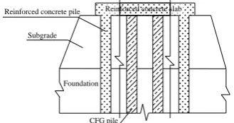
Because the reinforced concrete pile is rigid and rigidly connected to the slab, the pile-soil stress ratio of normal pile-slab structure is large. Therefore, the structure will failure before the piles reach their bearing limits and then cause some waste. In order to cut the cost and improve the efficiency for high-speed railway construction, the CFG pile are substituted for the reinforced concrete piles, except the piles under the slab edges, and connected to the slab. The reinforced concrete piles under the slab edges are still rigidly connected to the slabs as to limit their horizontal displacement. The improved structure is named as the new CFG pile-slab structure (Figure 2). CFG is a kind of composite material which is composed of cement, fly-ash and gravel. CFG pile is a new kind of high strength pile which uses CFG as the pile body material.
At present, the new CFG pile-slab structure is used for settlement controlling common for Shanghai-chengdu high-speed railway for the first time. But there is no corresponding design code for the new CFG pile-slab structure. The theoretical research seriously lags behind engineering practice, so it is necessary to establish a formula to accurately calculate the settlement and provide theoretical guidance for the engineering designs.
2. MECHANISM OF THE NEW STRUCTURE
The main mechanism of new CFG pile-slab structure is: the upper loads from the vehicles transfer from the slab to the pile; the pile spreads the loads to the adjacent soil and the soft foundation. The interactions between pile, slab and the soft foundation help to reduce the settlements and deformation of the whole soft soil subgrade. The strengthening mechanism of CFG pile-slab structural subgrade can be summarized as pile effects of replacement, compaction and reinforcement as
well as slab effects of adjusting and homogenizing the external loads. The slab
,
bottom soil, soil between pile and the soil under the pile tip are all involved in taking the vertical loads. The slab, pile groups and soil form a system of interaction and cooperation which improve the bearing capacity of new CFG pile-slab structure. In the design of new CFG pile-slab structure, the slab is generally regarded as a component which contacts each piles and transfers the upper loads to the piles. It is studied that the mechanism between pile and bearing slab is the same as that between concrete and steel in reinforced concrete which redistribute and adjust stresses to each other.In fact, the main part of pile and bearing slab share loads together with the soil. With the increase of upper loads, more loads begin to transfer from soil to the pile. While more loads transfer to the pile, smaller loads will be assigned to the soil. For the friction pile group, the sink of bearing slab could cause the sink of the soil and then the bearing slab will transfer some loads to the pile. The pile settlements will increase due to the increased load which will cause further compression force between soil and piles. Pile penetration deformation and compression of the soil between piles go through the cyclic and coordinating process. It can be said that the interaction and mutual influence between the pile and slab could be a way to control the foundation settlement.
3.CURRENT CALCULATION METHODS
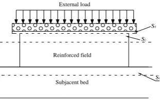
The settlement of the pile-slab structural subgrade can be recognized as three parts, the settlement deformation diagram is shown in Figure 3.
Subgrade
Foundation
Reinforced concrete pile
Reinforced concrete slab
Figure 1. Illustration of normal pile-slab structure
CFG pile Subgrade
Foundation
Reinforced concrete pile Reinforced concrete slab
Reinforced field
Subjacent bed External load
S3
S2
S1
Figure 3. Settlement of the pile-slab structural subgrade
Calculation of this settlement is given in formula (1).
1 2 3
S S S S (1)
In formula 1, S is the settlement of the pile-slab structural subgrade, S1 the subjacent bed deformation of reinforced field, S2 the compression deformation of soil around the pile, and S3 the compression deformation of bearing slab.
Because the slab has very small thickness and large stiffness, the compression deformation of bearing slab can be neglected. There are two kinds of common methods to calculate the S1 and S2in China. These are discussed as below.
3. 1. Stress Correction Method The basic idea
of stress correction method is: Suppose the compression of piles and soil between piles are identical, the compression amount of new CFG pile-slab structure can be calculated according to the compression amount of soil. When calculating the compression space of the soil between piles, the effect of pile bodies is neglected. Based on the load transfer between soil and piles, the settlement of the pile-slab structural subgrade can be calculated by layer-wise summation method. The additional stresses at reinforced field caused by external loads are used to calculate S1, and the additional stresses at subjacent bed caused by external loads are used to calculate S2.
When the external loads are less than the bearing capacity of new CFG pile-slab structure, the settlement can be calculated by the following formula.
2 1
1 2
1 1
n m
j i
i j
i si j sj
S S S h h
E E
(2)where n and m are the number of soil layers in reinforced field and in subjacent bed.
1i
and
2j
are
average additional stress at the layer i in reinforced field and at the layer j in subjacent bed.
si
E and Esjare the compression modulus of layer i in reinforced field and layer j in subjacent, hi and hj are the thickness of layer i in reinforced field and layer j in subjacent bed.
the empirical coefficient which can be selected in Chinese railway standard (TB10106—2010).
3. 2. Composite Modulus Method The principle of composite modulus method is: regarding the reinforcement field area and subjacent bed area of new CFG pile-slab structure as a whole. The compression property of the whole composite is characterized by a composite compression modulus Es, and the layer-wise summation method is used to calculate the compression of reinforcement area.
In the calculation, the foundation is divided into several layers according to the geological conditions [16, 17]. It is assumed that the composite soil in the reinforcement area is homogeneous, i.e. it is the same as the layers of natural foundation, but the compression modulus of composite soil is expanded ξ times, so the settlement of the reinforcement area and the subjacent bed can be calculated by layer-wise summation method.
When the external loads are less than the bearing capacity of new CFG pile-slab structure, the total settlement S is given by:
1 2
1 1
n m
i i
i j
i i si j n sj
S S S h h
E E
(3)where
n
is soil layers of reinforced field, m totals
oil layers,i
average additional stress at the layer i,
si
E
the compression modulus of layer i,
i
h the thickness of
layer i, and
i amplification factor of compression modulus for soil at layer i and is given by:,
sp k i
ki
f
f
(4)where ƒsp is standard value of bearing capacity for new
CFG pile-slab structure subgrade, and ƒkstandard value
of bearing capacity for natural foundation.
The composite modulus method needs to calculate the stress of the pile body, but the stress calculation of pile body involve some parameters which is difficult to obtain such as the distribution of friction resistance. Therefore, it is necessary to further establish a new calculation method which is suitable for new CFG pile-slab structure.
4. NEW ANALYTIC METHOD
4. 1. Calculation Method In order to overcome the
4. 1. 1. Establishment of Differential Equation
Because the slabs are laid out along the longitudinal direction of subgrade, the slabs can be supposed to be a beam with infinite length, so the boundary conditions of a single slab can be assumed to be fixed as shown in Figure 4. Figure 4 shows the model of slab settlement under the concentrated load P, according to Winkler foundation model, there is a differential equation as following. 0 ) ( d ) ( d 4 2 uyx x
x y
EI (5)
Then the slab is divided into 2 parts as AC and CB, the solutions of Equation (1) can be given by:
x e C x e C x e C x e C x x x x x β β β β β β β β cos sin cos sin ) ( y 4 3 2 1 1
(6)
x e D x e D x e D x e D x x x x x β β β β β β β β cos sin cos sin ) ( y 4 3 2 1 2
(7)
where EI is the flexural rigidity of the slab, u the bracing stiffness of subgrade under the slab and
4 4EI u β .
In order to simplify the calculation, let
) sin (cos s ) sin -(cos cos 4 3 2 1 x x e x f x in e x f x x e x f x e x f x x x x β β ) (β β ) (β β β ) (β β ) (β β β β β (8)
Then Equations (6) and (7) can begiven by:
)] ( ) ( ) ( ) ( [ 4 ) ( y )] ( ) ( ) ( ) ( [ 2 ) ( y )] ( ) ( ) ( ) ( [ 2 ) ( y )] ( ) ( ) ( ) ( [ ) ( y ) ( ) ( ) ( ) ( ) ( y 1 4 3 3 1 2 3 1 4 ) 4 ( 1 4 4 2 3 4 2 2 1 3 1 3 4 1 3 3 2 1 1 2 1 2 4 4 3 2 2 4 1 1 1 4 3 3 1 2 3 1 1 x f C x f C x f C x f C x x f C x f C x f C x f C x x f C x f C x f C x f C x x f C x f C x f C x f C x x f C x f C x f C x f C x β β β β β β β β β β β β β β β β β β β β β β β β (9)
Figure 4. Stress analysis model of slab
)] ( ) ( ) ( ) ( [ 4 ) ( y )] ( ) ( ) ( ) ( [ 2 ) ( y )] ( ) ( ) ( ) ( [ 2 ) ( y )] ( ) ( ) ( ) ( [ ) ( y ) ( ) ( ) ( ) ( ) ( y 1 4 3 3 1 2 3 1 4 ) 4 ( 2 4 4 2 3 4 2 2 1 3 2 3 4 1 3 3 2 1 1 2 2 2 4 4 3 2 2 4 1 2 1 4 3 3 1 2 3 1 2 x f D x f D x f D x f C x x f D x f D x f D x f C x x f D x f D x f D x f C x x f D x f D x f D x f D x x f D x f D x f D x f D x β β β β β β β β β β β
β β β
β β β β β β β β β β (10)
4. 1. 2. Boundary Conditions According to Figure 4, there are boundary conditions as follows. When X1=0,
0 ) 0 ( y ) ( y 0 ) 0 ( y ) ( y 1 1 1 1 1 1 x x
when X1=a, X2=0, P a a a a ) 0 ( EIy ) ( EIy -) 0 ( y ) ( y ) 0 ( y ) ( y ) 0 ( y ) ( y 2 1 2 1 2 1 2 1
when X2=L-a=b,
0 ) ( y 0 ) b ( y 2 2 b
According to the above 8 boundary conditions, 8 equations can be formulated:
0 4 2 C
C (11)
0
4 3 2
1C C C
C (12) 4 2 1 4 3 3 1 2 3 1 D D a f C a f C a f C a f C
(β( β)) (β ) (β ) (13)
4 3 2 1 2 4 4 3 2 2 4 1 D D D D a f C a f C a f C a f C
(β( β))(β ) (β ) (14)
3 1 3 4 1 3 3 2 1 1 D D a f C a f C a f C a f C
(β( )β) (β ) (β ) (15)
4 3 2 1 3 4 4 2 3 4 2 2 1
2 EI D D D D
P a f C a f C a f C a f C β ) β ( ) β ( ) (β ) (β (16) 0 b b 1 4 3 3 1 2 3 1
D (βf( β)b) (β ) (β ) f D f D b f D (17)1 0 b b 2 4 4 3 2 2 4 1
Using D4 to replace D1 to D3 in Equations (13), (14) and (15), then 4 1 4 3 3 3 4 1 3 4
1 (2 )
D a f C a f C a f C a f C C D
( β ) (β()β )(β ) (19)
4 1 4 3 3 1 4 3 3 4
2 (2 )
D a f C a f C a f C a f C C D
( β) (β( )β)(β ) (20)
4 3 4 3 1 4 3
3 ( ) ( )
D a f C C a f C C D
(β ) (β ) (21)
Substituting Equations (19), (20) and (21) into Equation (16), then ) ( 8 ) ( 1 ) ( ) ( 3 3 3 4 3 1 4 3 a f EI P a f D a f a f C C β β β β β (22) Let ) ( 8 3 3 1 a f EI P P β β
(23) ) ( ) ( m 3 1 a f a f β β (24) ) ( 1 n 3 a
f β
(25)
ThenEquation (22) can be changed to:
n
m
44 1
3
P
C
D
C
(26) Let)]
(
)
(
[
P
P
2
1
f
1β
a
f
3
β
a
(27))] ( ) ( [ )] ( ) ( ) ( 2 [ 3 1 1 3 1 a f a f m a f a f a f J β β β β β (28) 1 )] ( ) (
[ 1 3
n f a f a
K β β (29)
)] ( ) ( [ P
P3 1 f3βa f3 βa (30)
)] ( ) ( [ )] ( ) ( ) ( 2 [ 3 3 1 1 3 a f a f m a f a f a f g β
β β β β
(31)
1
)]
(
)
(
[
3
3
n
f
a
f
a
h
β
β
(32))]
(
)
(
[
P
P
4
1
f
1
β
a
f
3
β
a
(33))] ( ) ( [ )] ( ) ( [ 3 1 1 3 a f a f m a f a f r β β β β
(34)
1
)]
(
)
(
[
1
3
n
f
a
f
a
h
β
β
(35)Substituting Equations (26)- (35) into Equations (19)- (21), then K D J C P
D1 2 4 4 (36)
h D g C P
D2 3 4 4 (37)
t D r C P
D3 4 4 4 (38)
Let )] ( ) ( ) ( [ 3 4 1 3 3 2 5 b f P b f P b f P P
β β β
(39)
) ( ) ( g ) ( 3 1 3 b f r b f b f J u
ββ β
(40)
) ( ) ( ) ( h ) ( 1 3 1 3 b f b f t b f b f K v
β β β β
(41)
)] ( ) ( ) ( [ 4 4 2 3 4 2 6 b f P b f P b f P P
β β β
(42)
) ( ) ( g ) ( 4 2 4 b f r b f b f J s
ββ β
(43)
) ( ) ( ) ( h ) ( 2 4 2 4 b f b f t b f b f K w
β β β β
(44)
Substituting Equations (36)- (44) into Equations (13)- (14), then u w s v w P v P C
6 5
4 (45) u w s v s P u P D
6 5
4 (46)
4. 2. Steps of Solving the Equations
4. 2. 1. Solving The Intermediate Variable Step
1, ―P1‖, ―m‖and ―n‖ can be solved by substituting
known conditions into Equations (23)- (25).
Step 2, ―P2‖, ―J‖and ―K‖ can be solved by substituting
known conditions into Equations (27)- (29).
Step 3, ―P3‖, ―g‖and ―h‖ can be solved by substituting
known conditions into Equations (30)- (32).
Step 4, ―P4‖, ―r‖and ―t‖ can be solved by substituting
known conditions into Equations (33)- (35).
Step 5, ―P5‖, ―u‖ and ―v‖ can be solved by substituting
known conditions into Equations (39)- (41).
Step 6, ―P6‖, ―s‖ and ―w‖ can be solved by substituting
known conditions into Equations (42)- (44).
(26)
(27)
(28)
(29)
(30)
(31)
(32)
(33)
(34)
(35)
(36)
(37)
(38)
(39)
(40)
(41)
(42)
(43)
4. 2. 2. For C1~C4 and D1~D4 Step 1, ―C4‖ and
―D4‖ can be solved by substituting intermediate variable
into Equations (41)- (42).
Step 2, ―D1‖, ―D2‖ and ―D3‖ can be solved by
substituting intermediate variable and solutions from Step1 into Equations (36)- (38).
Step 3, ―C3‖ can be solved by substituting intermediate
variable and solutions above into Equation (26).
Step 3, ―C1‖ and ―C2‖ can be solved by substituting solutions above into Equations (11) and (12).
4. 2. 3. Other Solutions Substituting C1-C4 and D1
-D4 into Equations (9) and (10), the displacement, shear force, bending moment and ground reaction force can be solved.
5. FIELD MONITORING AND CALCULATION OF NEW CFG PILE-SLAB STRUCTURAL SUBGRADE
This study selects a sample soft soil subgrade of high-speed railway and use the above calculation method to calculate the settlement of soft soil subgrade. We aim to find the best method for settlement calculation of CFG pile-slab structural subgrade through the comparative analysis among the above 3 methods.
5. 1. Basic Parameters of Foundation Soil The
soft soil foundation taken from Shanghai -chengdu high-speed railway soft soil subgrade in China is analyzed in this study. The detailed information of each soil layer from top to bottom are given as follows: Level 1: clay, taupe, wet, loose, including life and construction waste. Layer thickness: 0.50~ 1.00 m. Level 2: silty clay, puce, soft plastic, local plastic flow. Layer thickness: 12~ 30 m.
Level 3: clay loam, tawny, soft plastic, local plastic flow. Layer thickness: 10~13 m.
Level 4: silt, taupe, soft plastic, section slightly smooth. The underground water depth is 4.8~5.2m, the underground water consists of Quaternary pore water and bedrock fissure water. The physical and mechanical properties of each soil layers are shown in Table 1.
5. 2. Problem Specification The pile diameter is
0.5 m. The effective pile length is 15 m.
TABLE 1. Summary table of physical and mechanical properties of the layered soil
Layer
number Soil layer W (%) (kN/m3) e
Es (MPa)
1 clay 31.9 19.2 0.89 4.61
2 silty clay 43.5 17.9 1.22 2.55
3 clay loam 35.0 18.8 0.97 8.77
4 Silt layer - - - 28.25
Pile spacing is 2.5 m. The size of bearing slab is 12.5 m (length)×10 m(width)×0.70 m(thickness). The ultimate bearing capacity of a single pile is 500KPa. The vertical external loads are acting on the top of the bearing slab. The bearing capacity of composite foundation is required to reach 240 KPa.
5. 3. Settlement Control of New CFG Pile-slab
Structure The measuring point was laid out at
the engineering field. The high precision electronic equipment recorded the settlement of natural foundation and new CFG pile-slab structure. According to the comparative analysis between the settlement of
natural foundation and new CFG pile-slab structure (Figure 5), it is seen that the settlement of new CFG pile-slab structure is smaller than natural foundation for the same load. The new CFG pile-slab structure can reduce the settlement of natural foundation from 88.3mm to 33.4mm when p=300 kPa. The settlement of new CFG pile-slab structure was also smaller than the admissible value of high-speed railway subgrade of China. It can be concluded that the settlement control of new CFG pile-slab structure can satisfy the engineering requirement.
5. 4. Results and Discussion Based on the above
three methods for calculating the settlement of CFG pile slab structure, the results are compared with the field monitoring data and are shown in Figures 6 and 7.
Figure 5. The contrast picture of ground subsidence when p=300kPa
Figure 6. The relationship between force and settlement
0 10 20 30 40 50 60 70 80 90 100
S(m
m)
Natural foudation New CFG pile-slab structure
Admissible value
0 5 10 15 20 25 30 35 40 45
0 50 100 150 200 250 300 External force(KPa)
Set
tlem
ent
(mm
)
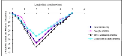
Figure 7. The settlement curves along the longitudinal coordinate when p=300 kPa
Figures 5 and 6 show that the biggest settlement of the new CFG pile-slab structure measured by field monitoring is 33.4 mm while the biggest settlement calculated by new analytic method is 34.6 mm. The settlements at the slab edges calculated by all the three methods are totally similar, but the calculated settlements at the middle parts of slabs are different. The settlement curves of new analytic method are most similar with curves of field monitoring. Therefore, it can be concluded that the new analytic method can reflect the common deformation and mechanism of the new
CFG pile-slab structure and should be suitable for its use in engineering designs.
6.CONCLUSION
This paper proposed a new CFG pile-slab structure and derived the new analytic method for settlement calculation. A comparative study is performed on the calculation of settlement for new CFG pile-slab structural subgrade based on three settlement calculation method. The following conclusions can be drawn: 1) The interactional and mutual influence between the CFG piles, reinforced concrete piles and slab cause the foundation settlement controlling effect. Both the field monitoring results and calculations show that the new CFG pile-slab structure can reduce the settlement of
natural foundation and meet the settlement requirement of high-speed railway subgrade in China.
2) The new analytic method is proved to be more accurate than stress correction method and composite modulus method.With the new analytic method presented in this paper,the flexure deformation of slab, and the load bearing between different piles and slab can be solved. The calculation result can reflect the common mechanical properties of the CFG pile-slab structure. Furthermore,it can provide theoretical guidance for future research and engineering designs.
7. ACKNOWLEDGEMENTS
The authors gratefully acknowledge the support of Natural Science Foundation of Hubei Province
(2015CFB359), Natural Science Foundation of Hubei Provincial Department of Education (Q20154403), and
HBPU’s Foundation of Innovative
talents(15xjz02C).
8. REFERENCES
1. X, Z. and J, S., "Least squares support vector machine for constitutive modeling of clay", International Journal of
Engineering Transaction B: Applications, Vol. 28, (2015),
1571-1578.
2. Zhang, X., Yang, G. and Chen, R., "Field test study of pile-soil stress ratio and cushion effect of cm-piles composite foundation", Rock and Soil Mechanics, Vol. 36, No., (2015), 357-360.
3. Shafabakhsh, G. and Ahmadi, S., "Evaluation of coal waste ash and rice husk ash on properties of pervious concrete pavement",
International Journal of Engineering-Transactions B:
Applications, Vol. 29, No. 2, (2016), 192-201.
4. QI, L., SHI, J.-y. and HOU, Q., "Research on pile penetration into cushion of composite ground", Rock and Soil Mechanics, Vol. 3, (2011), 815-819.
5. Jin-bo, L., Jiang, H.-d. and Zheng, Y.-y., "Calculation and analysis of composite pile-soil stress ratio of composite foundation with capped rigid pile", Chinese Journal of
Geotechnical Engineering, Vol. 27, No. 11, (2005),
1300-1305.
6. Abusharar, S.W., Zheng, J.-J. and Chen, B.-G., "Finite element modeling of the consolidation behavior of multi-column supported road embankment", Computers and Geotechnics, Vol. 36, No. 4, (2009), 676-685.
7. Guang-Hua, Y., Bu-Kun, S. and You-Liang, Q., "Method for calculating settlement of rigid-pile composite foundation",
Chinese Journal of Rock Mechanics and Engineering, Vol.
28, No. 11, (2009), 2193-2200.
8. Ng, C.W., Poulos, H.G., Chan, V.S., Lam, S.S. and Chan, G.C., "Effects of tip location and shielding on piles in consolidating ground", Journal of Geotechnical and Geoenvironmental
Engineering, Vol. 134, No. 9, (2008), 1245-1260.
9. Baojun, L., Kunquan, M. and Xinxin, Z., "Study on dynamic property of pile-plank embankment used in high-speed railway with slab-track", Journal of Shijiazhuang Tiedao University
(Natural Science), Vol. 1, (2011), 63-68.
10. Jiang, Y., Han, J. and Zheng, G., "Numerical analysis of a pile– slab-supported railway embankment", Acta Geotechnica, Vol. 9, No. 3, (2014), 499-511.
11. Moayed, R.Z., Izadi, E. and Mirsepahi, M., "3d finite elements analysis of vertically loaded composite piled raft", Journal of
Central South University, Vol. 20, No. 6, (2013), 1713-1723.
12. Huang, Q. and Liu, F., "Research on pile-sheet structure of loess subgrade in passenger railway line from baoji to lanzhou",
Journal of Lanzhou Institute of Technology, Vol. 23, (2016),
15-18.
13. Z, L., H, B. and Q, S., "Applicability analysis of non-embedded pile-board subgrade in soft soil area", Railway Engineering, Vol. 39, (2016), 135-138.
14. Okyay, U., Dias, D., Billion, P., Vandeputte, D. and Courtois, A., "Impedance functions of slab foundations with rigid piles",
Geotechnical and Geological Engineering, Vol. 30, No. 4,
(2012), 1013-1024.
15. Zhan, Y.-x., Yao, H.-l. and Jiang, G.-l., "Design method of pile-slab structure roadbed of ballastless track on soil subgrade",
Journal of Central South University, Vol. 20, (2013), 2072-2082.
0 5 10 15 20 25 30 35 40 45
0 1 2 3 4 5 6
Longitudinal coordinate(mm)
Set
tlem
ent
und
er
the
ext
erna
l
forc
e(m
m)
16. Kermani, H., Behnamfar, F. and Morsali, V., "Seismic design of steel structures based on ductility and incremental nonlinear dynamic analysis", International Journal of
Engineering-Transactions A: Basics, Vol. 29, No. 1, (2015), 23.
17. Shooshpashaa, I., Mola-Abasia, H. and Amirib, I., "Evaluation of static and dynamic methods for determining the bearing capacity of the driven pipe piles", International Journal of
Engineering, Vol., No. 2, (2014), 307-314.
New Analytic Method for Subgrade Settlement Calculation of the New Cement
Fly-ash Grave Pile-slab Structure
D. B. Zhang, Y. Zhang, T. Cheng, J. Y. Yuan
School of Civil Engineering, Hubei Polytechnic University, Huangshi, China
P A P E R I N F O
Paper history: Received 08 July 2016
Received in revised form 24 July 2016 Accepted 27 August 2016
Keywords:
Cement Fly-ash Grave Pile New Pile-slab Structure Settlement Calculation New Analytic Method
ديكچ ه
ُزٍرها صّاک تسطً رتسب کاخ مرً لکطه لصا ی رد تخاس ٍ زاس ُار يّآ اّراطق ی تػرس تسلااب . راتخاس ىَتس
ِتخت ا ی ی ک عًَ رتسب رپ دربراک ارب ی صّاک تسطً رتسب رد رَطک چ ی ي تسا . ِب رَظٌه صّاک سّ ی ٌِ اّ ی سذٌْه ی رد
تخاس ُار يّآ اب تػرس لااب رد اّرَطک ی رد لاح ،ِؼسَت ًَ ی ُذٌس ی ا ی ي ِلاقه ی ک راتخاس غوض لاد حارط ی ٍ ىآ ار اب
ماً CFG راتخاس غوض لاد ذج ی ذ فرؼه ی ُدرک تسا . رد ا ی ي ،صٍّژپ تارثا لرتٌک ی تسطً راتخاس CFG ذج ی ذ لحت ی ل ٍ
ٍد شٍر ِبساحه تسطً رتسب فرؼه ی ُذض ٍ سپس اب ِب ترَص ی ک شٍر تابساحه ی ِصلاخ ُذض تسا . ارب ی ِبساحه
رتسب اپ ی ِ ی کاخ مرً ُار يّآ رس ی غ اْگًاض ی -ٍذگٌچ ِب شٍر CFG زا ِس شٍر ُدافتسا ذض . صٍّژپ ىاطً داد ِک ( : 1 )
رثا لرتٌک ی CFG راتخاس غوض لاد ه ی ذًاَت ً ی زا ِب تخاس ٍ زاس يّآ رس ی غ ار ُدرٍآرب دزاس ( . 2 ) شٍر لحت یل ی ذج ی ذ
تباث ُدرک تسا ِک قد ی ق رت تسا ٍ ه ی ذًاَت راکٍزاس لاقتًا راب ار سکؼٌه ذٌک . ٍُلاػ رب ا ی ،ي شٍر لحت یل ی ذج ی ذ ه ی
ذًاَت اوٌّار ی رظً ی بَخ ی ار ارب ی حرط اّ ی سذٌْه ی ٍ ُزاس اّ ی CFG راتخاس غوض لاد نّارف ذٌک