Please cite this article as: M. H. Holakooie, M. B. Banna Sharifian,M.R. Feyzi, Sensorless Indirect Field Oriented Control of Single-Sided Linear Induction Motor With a Novel Sliding Mode MRAS Speed Estimator, International Journal of Engineering (IJE), TRANSACTIONS A: Basics Vol. 28, No. 7, (July 2015) 1011-1020
International Journal of Engineering
J o u r n a l H o m e p a g e : w w w . i j e . i rSensorless Indirect Field Oriented Control of Single-sided Linear Induction Motor
With a Novel Sliding Mode MRAS Speed Estimator
M. H. Holakooie*, M. B. Banna Sharifian, M. R. Feyzi
Department of Electrical and Computer Engineering, University of Tabriz, Tabriz, Iran
P A P E R I N F O
Paper history: Received 12 January 2015
Received in revised form 21 March 2015 Accepted 11 June 2015
Keywords:
Indirect Field Oriented Control (IFOC) Model Reference Adaptive System (MRAS) Sensorless
Sliding Mode Control (SMC)
Single-Sided Linear Induction Motor (SLIM)
A B S T R A C T
This paper proposes a new sliding mode control (SMC) based model reference adaptive system (MRAS) for sensorless indirect field oriented control (IFOC) of a single-sided linear induction motor (SLIM). The operation of MRAS speed estimators dramatically depends on adaptation mechanism. Fixed-gain PI controller is conventionally used for this purpose which may fail to estimate the speed correctly in different condition such as variation in the machine parameters. In this paper, PI controller is replaced by SMC based adaptation mechanism. One of the major problems of SMC is high-frequency chattering due to switching control function. In order to alleviate this problem, a new switching control function is presented. The SMC parameters are tuned using an off-line method through chaotic optimization algorithm (COA) because no design criterion is given to provide these values. The operation of sliding mode MRAS speed estimators (SM-MRAS) is validated by numerical simulation especially at very low speed because this range of speed is very critical for estimators. The simulation results confirm the efficiency of proposed adaptation mechanism.
doi: 10.5829/idosi.ije.2015.28.07a.07
NOMENCLATURE s
i ,ir Primary and secondary currents Rs, Rr Primary and secondary resistances
j Imaginary unit TvLp/vl Time of traverse an imaginary point by the primary core
p K
,KI Proportional and integral gains of PI controller vs, vr Primary and secondary voltages
v
K SMC positive integral gain vl, vˆl Real and estimated linear speed
ls
L ,Llr Primary and secondary leakage inductance Greek Symbols
m
L Magnetizing inductance s,r Primary and secondary flux linkages
s
L ,Lr Primary and secondary self inductances Pole pitch
p
L Primary length r,ˆr Real and estimated angular velocity
m,M Moving mass, modified magnetizing inductance e Synchronous angular velocity
c
M , Mp Conventional and proposed SMC positive control gains sl Slip angular velocity p, P Differential operator, pole number
1. INTRODUCTION1
Recently, linear induction motors (LIMs) have been widely used in industrial applications such as transportation systems, conveyer in factory production
1 1*Corresponding Author’s Email:[email protected](M. H. Holakooie)
M. H. Holakooie et al./ IJE TRANSACTIONS A: Basics Vol. 28, No. 7, (July 2015) 1011-1020 1012
longitudinal and transversal direction which creates the so-called longitudinal end effect and transversal edge effect, respectively. These phenomena increase the complexity of the SLIM model as well as complicate proper control of electromechanical characteristics of the SLIM such as thrust, magnetic flux and linear speed [1-3].
Utilization of an efficient dynamic model for LIMs, including longitudinal end effect and transversal edge effect strongly influences on the quality of control variables. From the viewpoint of modeling, the dynamic and steady-state behaviour of LIM has been vastly developed in technical literatures. Winding function is an accurate and powerful approach to analysis the performance of all types of machine, especially healty/faulty three-phase and multi-phase rotary induction motors (RIMs) [4, 5] and also LIMs. In the case of LIM, Nondal et al. [6] and Wei xu et al. [7] have obtained equivalent circuit using winding function theory for high speed double-sided linear induction motor (DLIM) and SLIM respectively. Pai et al. [8] have proposed an equivalent circuit based on field theory which longitudinal end effect, transversal edge effect, field diffusion in the secondary sheet and back-iron saturation has been considered. Moreover, some researchers utilize one-dimensional (1-D) and two-dimensional (2-D) field theory to obtain equivalent circuit of the LIM [9-11]. However, the majority of these equivalent circuits describe the steady-state behavior of the LIM. Huang et al. [12] consider longitudinal end effect as a braking force in mechanical equation of the SLIM. This model is based on the fact that the final impact of the longitudinal end effect is creating of a braking force as a function of linear speed. Duncan in [13], describes the longitudinal end effect as a coefficient related to the linear speed. This coefficient is used to modify the magnetizing branch of the SLIM equivalent circuit. Some details of this approach, due to employing in this paper, are presented in the following section.
Satisfactory control of electromechanical characteristics of the SLIM is another challenging problem for the researchers. To address the mentioned subject, indirect field-oriented control (IFOC) strategies have been developed based on duncan's model [14, 15]. The direct field-oriented control (DFOC) and direct torque control (DTC) methods have been discussed in [16] and [17], respectively. For each of control strategies with the speed loop, the speed/position is conventionally measured by a linear encoder which is expensive and has low reliability. Therefore, obtaining a high-performance sensorless control of the SLIM is very important work. In the case of RIM, many sensorless approaches are successfully tested such as MRAS based speed estimator [18, 19], sliding-mode observer [20], Kalman's filter observer [21], Reduced-order nonlinear observer [22] and full-Reduced-order Luenberger
observer [23], while due to complexity of the SLIM model, very few investigations have been proposed in this way. In particular, MRAS based speed estimator has been introduced in [24]. A fuzzy observer has been presented to estimate the linear speed and secondary flux [25]. Full-order Luenberger observer has also been investigated to estimate all state-space variables of the SLIM [26].
In this paper, a new SM-MRAS speed estimator is presented for sensorless IFOC of SLIM. The SMC strategy is adopted instead conventional PI controller as the adaptation mechanism to estimate linear speed from speed tuning signal, especially at very low speeds because of poor operation of the MRAS speed estimator at low speeds. Moreover, the IFOC strategy, which has been described in [15], is used to proper control of the magnetic flux and the linear speed. Optimum parameters of SMC are determined by an off-line method through COA. The performance and robustness of the proposed SM-MRAS speed estimator are verified in different conditions, including normal condition, noisy condition, load force change and machine parameter change.
This paper is organized as follows. Section 2 introduces the dynamic model of SLIM. Section 3 describes secondary flux estimator. Section 4 presents the structure of MRAS speed estimator. Section 5 deals with SMC based adaptation mechanism. The COA is discussed in Section 6. Simulation results are presented in Section 7. Finally, Section 8 summarizes the finding and concludes the paper.
2. DYNAMIC MODEL of SLIM
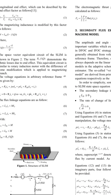
The structure of SLIM is shown in Figure 1. It consists of primary (moving part), secondary sheet, back iron and three-phase winding. The primary part is similar to the stator in the rotary induction motor (RIM). Moreover, total secondary sheet and back iron (In summary, the secondary part) is operated as squirrel-cage rotor in the RIM. In the LIM, during the primary movement, the secondary is continuously replaced by a new material. Because of appearance of this new material, the air-gap flux density is gradually (not suddenly) increased at the entry of primary with total secondary time constant which is described by:
r lr m
r L L R
longitudinal end effect, which can be described by the end effect factor as follows[13]:
r lr m l p r v R L L v L T T Q / ) ( / (1)
The magnetizing inductance is modified by this factor as follows:
)) ( 1
( f Q
L
M m (2)
where,
Q e Q
f( )1 Q (3)
The space vector equivalent circuit of the SLIM is shown in Figure 2. The term Rrf(Q) demonstrate the ohmic losses due to end effect. This equivalent circuit is similar to rotary induction motor with the difference of some modification which is applied to magnetizing branch.
The voltage equations in arbitrary reference frame are given by:
) (s r sh s s s s
s Ri j p R i i
v (4)
r r r r r r sh s r
v 0 R i j ( ) p R i i( ) (5)
The flux linkage equations are as follow:
r s s sLi Mi
(6)
s r r r Li Mi
(7)
With:
M L
Ls ls (8)
M L
Lr lr (9)
) (Q f R
Rsh r (10)
Figure 1.Structure of SLIM
Figure 2.Space vector equivalent circuit of SLIM
The electromagnetic thrust generated by the LIM is calculated as follows:
) Re( 2 2 3 s s
e P j i
F
(11)
3. SECONDATY FLUX ESTIMATORS BASED on MACHINE MODEL
The amplitude and angle of flux linkage are two important variables which exactly need to be estimated in DFOC and IFOC strategy. The flux estimators are generally obtained from voltage equations in the same reference frame. Therefore, one of the flux estimators always depends on the linear speed. Employing the flux models in the adaptive scheme, establish MRAS speed estimator. The so-called “voltage model” and “current model” are derived from primary and secondary voltage equations respectively as the flux estimators.
In order to simplicity, some assumptions are applied to SLIM state space equation [8, 16]:
The secondary leakage inductance is almost zero. (Llr 0)
The rate of change of linear speed is almost zero.
( dt 0 dvl
)
Using Equation (4) in stationary reference frame (0) and Equations (6) and (7) and with some mathematical manipulation, the voltage model is derived as follows:
r sh s ls s s s
r v Ri pL i RM
p (12)
Using Equation (5) in stationary reference frame and Equations (6) and (7), the current model is obtained as follows: r r r sh r s r
r Ri R MR j
pˆ ˆ ˆ ˆ (13)
where, superscript “^” denotes the estimated secondary flux by current model. As regards that ˆr P v2 ˆl
M. H. Holakooie et al./ IJE TRANSACTIONS A: Basics Vol. 28, No. 7, (July 2015) 1011-1020 1014
Figure 3.The structure of voltage and current model
Figure 4.MRAS speed estimator
The voltage model and the current model, described by Equation (14), are shown in Figure 3. It should be noted that, the current model needs the linear speed to obtain secondary flux whereas the voltage model decouples from the linear speed.
4. MRAS SPEED ESTIMATOR
Among different schemes for sensorless control of induction machine, MRAS speed estimator is widely used because of the simple structure and low computational [18]. This estimator constitutes from two
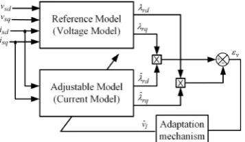
different models that both of them estimate the same state variable. One of these models is called reference model, and the other one is called adjustable model. The voltage and current model, described in previous section, are considered as reference and adjustable model, respectively. In this paper, the MRAS speed estimator is based on secondary flux, i.e. the voltage and current models estimate the secondary flux.
In the MRAS speed estimator strategy, the linear speed is operated as adaptive parameter and continuously returned to current model by an adaptation mechanism. The adaptation mechanism must be designed to ensure the stability of system. For this purpose, MRAS speed estimator is designed according to Popov’s hyperstability theory [27]. If Popov’s criterion is applied to state-space equation of SLIM by consideration a proper candidate adaptation mechanism such as PI controller, the speed tuning signal is acquired as follows:
rq rd rd rq
v
ˆ ˆ (15)
The structure of the MRAS speed estimator based on aforementioned speed tuning signal is shown in Figure 4.
In the conventional MRAS schemes, the PI controller is used as adaptation mechanism as follows:
p v I v
l K K
vˆ (16)
where vˆl is the estimated linear speed obtained from PI controler.
The PI controllers are generally used in industrial application because of simple structure. This controller can properly estimate the linear speed over wide range of speed.
However, some factors, such as the variation of the machine parameters, nonlinear properties of voltage source inverter and noise of measurement equipment, impress the operation of PI controller, especially at low speed [18]. In the next sections, the concept of utilization of a novel SMC as adaptation mechanism is proposed for SLIM.
5. SMC BASED ADAPTATION MECHANISM
variation of machine parameters, disturbance and measurement noise. Moreover, SMC has a simple structure for implementation in industrial applications [29]. From basic concept of SMC, the stability is guaranteed by keeping the system states on sliding surface. In this work, sliding surface is defined based on speed tuning signal as follows:
v Kv vs (17)
where, Kv is positive constant gain. In order to reaching the states of system to sliding surface and also to keep the trajectory of these states on the sliding surface, a switching control law must be defined using Lyapunov theory. For this purpose, Lyapunov function candidate is defined as follows [29]:
2
2 1s
v (18)
Regarding to Lyapunov stability theory, if the time derivative of Lyapunov function v is negative definite, the system states trajectory will continue in the sliding surface. The derivative of Lyapunov function can be calculated as follows:
s s
v (19)
According to Equation (17), the derivative of sliding surface s can be calculated as follows:
v v
v K
s (20)
and finally, from Equations (14) and (15), the derivative of speed tuning signal v can be written as follows:
2 1 vˆk
k l
v
(21)
with ) ˆ ˆ ( ) ( ˆ ˆ 1 rd rq rq rd sh r rd sq rq sd r rq rd rd rq M R R i i R k (22) ) ˆ ˆ ( 2
2 P rq rq rd rd
k
(23)
Substituting Equations (20) and (21) in (19) gives:
) ˆ
(k1 vlk2 Kv v
s
v (24)
Equation (24) is negative definite if the control law, for estimated linear speed, is provided as follows:
s e
l u u
vˆ (25)
Figure 5.Proposed and conventional control functions for SMC strategy
Figure 6.Adaptation mechanism based on proposed SMC
where, ue and us are the equivalent and switching control functions. The term ue can be written as follows: 2 1 k K k
ue vv (26)
The switching control functionsusmust continuously ensure the stability of system with respect to sign of sliding surface s. The sign function is conventionally adopted for this purpose. In this case, the term us is written as follows:
0 )
(
sign
c c
s M s M
u (27)
where, Mc is a positive control gain and
0 1 0 1 ) (
sign s ss (28)
One of the main problems of SMC is high-frequency chattering of estimated state of system (in here linear speed) due to switching control law. This problem becomes more complex when the system states are reached to sliding surface [18]. In fact, utilization of sign function in SMC strategy causes this problem and it is not possible to completely eliminate it. In this paper, in order to reduce the impact of chattering problem, the sign function is replaced by a new smooth function because of sudden changes in sign function. variation of machine parameters, disturbance and
measurement noise. Moreover, SMC has a simple structure for implementation in industrial applications [29]. From basic concept of SMC, the stability is guaranteed by keeping the system states on sliding surface. In this work, sliding surface is defined based on speed tuning signal as follows:
v Kv vs (17)
where, Kv is positive constant gain. In order to reaching the states of system to sliding surface and also to keep the trajectory of these states on the sliding surface, a switching control law must be defined using Lyapunov theory. For this purpose, Lyapunov function candidate is defined as follows [29]:
2
2 1s
v (18)
Regarding to Lyapunov stability theory, if the time derivative of Lyapunov function v is negative definite, the system states trajectory will continue in the sliding surface. The derivative of Lyapunov function can be calculated as follows:
s s
v (19)
According to Equation (17), the derivative of sliding surface s can be calculated as follows:
v v
v K
s (20)
and finally, from Equations (14) and (15), the derivative of speed tuning signal v can be written as follows:
2 1 vˆk
k l
v
(21)
with ) ˆ ˆ ( ) ( ˆ ˆ 1 rd rq rq rd sh r rd sq rq sd r rq rd rd rq M R R i i R k (22) ) ˆ ˆ ( 2
2 P rq rq rd rd
k
(23)
Substituting Equations (20) and (21) in (19) gives:
) ˆ
(k1 vlk2 Kv v
s
v (24)
Equation (24) is negative definite if the control law, for estimated linear speed, is provided as follows:
s e
l u u
vˆ (25)
Figure 5.Proposed and conventional control functions for SMC strategy
Figure 6.Adaptation mechanism based on proposed SMC
where, ue and us are the equivalent and switching control functions. The term ue can be written as follows: 2 1 k K k
ue vv (26)
The switching control functionsusmust continuously ensure the stability of system with respect to sign of sliding surface s. The sign function is conventionally adopted for this purpose. In this case, the term us is written as follows:
0 )
(
sign
c c
s M s M
u (27)
where, Mc is a positive control gain and
0 1 0 1 ) (
signs ss (28)
M. H. Holakooie et al./ IJE TRANSACTIONS A: Basics Vol. 28, No. 7, (July 2015) 1011-1020 1016
With regard to this replacement, the proposed switching control function is defined as follows:
) (s G M
usp p (29)
similarly Mpis a positive control gain and
1 1
2 )
( 2
s
e s
G (30)
Regarding above equation, when s yields the 1
) (s
G . Hence, the final behaviour of the proposed function is similar to sign function. Around zero point,
) (s
G is varied depend on sliding surface s to ensure the stability of the system with reduced chattering. Figure 5 shows conventional and proposed control functions for SMC strategy. Moreover, Figure 6 depicts the adaptation mechanism based on the proposed SMC strategy.
6. CHAOTIC OPTIMIZATION ALGORITHM
Many problems such as optimal design of SMC in the complex nonlinear system, can be developed as an optimization problem. Global optimum detection is one of the important factors in optimization algorithms. Many heuristic optimization algorithms have been introduced in technical literatures such as genetic algorithm (GA), particle swarm optimization (PSO), simulated annealing (SA) and chaotic optimization algorithm (COA), which try to find the global optimal point. The main features of COA are as follows [30, 31]:
It distinguishes between local and global optimal points by its inherent powerful structure,
It does not produce repetitive numbers in searching progress,
It is easily implemented and its running time is fairly short.
The COA usually has two main steps as follows[30]:
Step 1:Mapping a generated sequence of chaotic points from the chaotic space to the solution space and then providing the current optimum point with respect to the objective function.
Step 2: Obtaining the global optimal point using the current optimal point and chaotic dynamics.
Accurate determination of SMC parameters has a significant role in quality of estimated parameter. A trial-and-error method is conventionally adopted for such nonlinear problems. However, optimum
coefficients of the controllers may not be obtained by this method. An optimization technique such as COA, provides an intelligent trial-and-error process. As a result, in this paper, the COA is adopted to determine SMC coefficients. For this purpose, an objective function is defined as follows:
tsimt vldt f
0 (31)
where,
v
l is the error of real and estimated speed andsim
t
is the simulation time. The results of the COA for SMC coefficients are given in Appendix.7. RESULTS AND DISCUSSION
The operation of MRAS speed estimator with the proposed adaptation mechanism is verified using numerical simulation. For this purpose, the Matlab/Simulink software is adopted. The block diagram of the computer simulation model is shown in Figure 7. According to this figure, the linear speed is obtained using the terminal voltages and currents of the SLIM using MRAS speed estimator. Afterward, the estimated speed is used in the current decoupling network to provide the command values of currents in the synchronous reference frame. The current decoupling network provides both decoupled currents and accurate secondary flux position using secondary voltage (Equation (5)) in the synchronous reference frame. In the IFOC scheme, the flux position is calculated as
dt
dt e
r
sl
( ˆ ) (32)
whereslip angular velocity sl isrelated to SLIM parameters, thrust and secondary flux command [15]. The error of currents is applied to PI controller to provide voltage commands similarly in the synchronous reference frame. Some other details of IFOC strategy are presented in [15]. The parameters of SLIM used in this study are given in Appendix.
In this paper, in order to evaluate the performance of the proposed adaptation mechanism, the integral of the time multiplied absolute value of the error (ITAE) is used as an index in the following way:
tsimt vldt ITAE
0
Moreover, in this paper, the main focus is on the operation of the MRAS speed estimator at very low speeds because this range of speed is the most critical case for the estimators. The speed command is chosen
s m/ 2 .
0 which is 5% its nominal value.
The operation of MRAS speed estimator with PI, conventional and proposed SMC adaptation mechanisms in normal condition is shown in Figure 8 (a).The values of ITAE are 23.039, 28.285 and 24.353 for PI, conventional and proposed SMC, respectively. From these numbers, it is clear that in normal condition, by proper setting of adaptation mechanisms parameters with the COA, the performance of the all adaptation mechanisms are almost similar.
Figure 7.Block diagram of sensorless IFOC
Figure 8.The operation of MRAS speed estimator for (a) normal condition (b) noisy condition (c) load force change
Figure 9.The operation of MRAS speed estimator for secondary resistance change
Moreover, in this paper, the main focus is on the operation of the MRAS speed estimator at very low speeds because this range of speed is the most critical case for the estimators. The speed command is chosen
s m/ 2 .
0 which is 5% its nominal value.
The operation of MRAS speed estimator with PI, conventional and proposed SMC adaptation mechanisms in normal condition is shown in Figure 8 (a).The values of ITAE are 23.039, 28.285 and 24.353 for PI, conventional and proposed SMC, respectively. From these numbers, it is clear that in normal condition, by proper setting of adaptation mechanisms parameters with the COA, the performance of the all adaptation mechanisms are almost similar.
Figure 7.Block diagram of sensorless IFOC
Figure 8.The operation of MRAS speed estimator for (a) normal condition (b) noisy condition (c) load force change
M. H. Holakooie et al./ IJE TRANSACTIONS A: Basics Vol. 28, No. 7, (July 2015) 1011-1020 1018
The operation of MRAS speed estimator with PI, conventional and proposed SMC adaptation mechanisms at noisy condition is shown in Figure 8 (b). In this case, a white noise is applied in measured voltage and current signals. These signals are used as the input of the secondary flux estimators (voltage and current model). The ITAE is 133.959, 86.252 and 84.787 for PI, conventional and proposed SMC, respectively. The PI controller is dramatically impressed by measurement noise whereas the SMC adaptation mechanisms are more robust against noise. On the other hand, the proposed SMC alleviates high-frequency chattering compared with conventional SMC.
The behavior of the speed estimator with PI, conventional and proposed SMC adaptation mechanisms is shown in Figure 8 (c) when the load force disturbance is applied to the SLIM. In this case, the load force disturbance is increased, as a step function, from 0N to 50N at t2s.This case also confirms the robustness of SMC adaptation against PI controller.
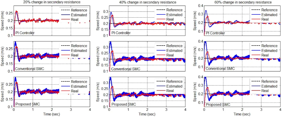
Finally, Figure 9 shows the operation of MRAS speed estimator with PI, conventional and proposed SMC adaptation mechanisms when secondary resistance increases 20, 40 and 60% due to some factors such as increase of secondary sheet temperature. For the 20% change in secondary resistance, the ITAE index is 43.435, 48.778 and 46.348 for PI, conventional and proposed SMC, respectively. These numbers are 103.777, 70.322 and 69.222 for the 60% change, by the same order. Regarding the aforementioned values, it is completely obvious that the SMC strategy is more robust against variations in the machine parameters. A summary of results about ITAE index in four described conditions is given in Table 1.
TABLE 1.The values of ITAE
Operating conditions controllerPI ConventionallSMC ProposedSMC
Normal condition 23.039 28.485 24.353
Noisy condition 133.959 86.252 84.787
Load force change 28.312 28.997 24.814
Secondary resistance change
20% 43.435 48.778 46.348
40% 74.140 61.174 59.152
60% 103.777 70.322 69.222
8. CONCLUSION
This paper deals with MRAS speed estimator for sensorless IFOC of an SLIM. In this regard, a new SM-MRAS speed estimator is presented. In this scheme, the adaptation mechanism is based on SMC strategy. One of the major problems of SMC is high-frequency chattering which this problem is investigated by defining a new control function instead of sign function. Moreover, the COA is adopted to determine the optimum values of SMC parameters as an intelligent trial-and-error process. In order to consider the integrity of research, four different operation conditions are considered, i.e., normal condition, noisy condition, load force change and secondary resistance change. The introduced performance index, i.e. ITAE, demonstrate that SMC improves the quality of speed estimation compared with conventional PI controller, particularly at very low speeds. On the other hand, comparison between conventional and proposed SMC shows that the proposed scheme has better performance because it alleviates chattering by defined control function.
9. REFERENCES
1. Boldea, I. and Nasar, S.A., "Linear electric actuators and generators", in Electric Machines and Drives Conference Record,. IEEE International, IEEE., (1997), MA1/1.1-MA1/1.5. 2. Boldea, I., "Linear electric machines, drives, and maglevs
handbook, CRC Press, (2013).
3. Gieras, J.F., "Linear induction drives, Oxford University Press, (1994).
4. Ojaghi, M., Sabouri, M., Faiz, J. and Ghorbanian, V., "Exact modeling and simulation of saturated induction motors with broken rotor bars fault using winding function approach",
International Journal of Engineering-Transactions A: Basics, Vol. 27, No. 1, (2013), 69-76.
5. Taheri, A. and Sabouri, M., "Magnetic saturation impacts on fault analysis of squirrel-cage six phases induction motors using winding function approach", International Journal of Engineering-Transactions C: Aspects, Vol. 27, No. 9, (2014), 1359.
6. Nondahl, T. and Novotny, D., "Three-phase pole-by-pole model of a linear induction machine", Electric Power Applications, IEE Proceedings B, Vol. 127, No. 2, (1980), 68-82.
7. Xu, W., Sun, G., Wen, G., Wu, Z. and Chu, P.K., "Equivalent circuit derivation and performance analysis of a single-sided linear induction motor based on the winding function theory",
Vehicular Technology, IEEE Transactions on, Vol. 61, No. 4, (2012), 1515-1525.
8. Pai, R., Boldea, I. and Nasar, S., "A complete equivalent circuit of a linear induction motor with sheet secondary",Magnetics, IEEE Transactions on, Vol. 24, No. 1, (1988), 639-654. 9. Gieras, J., Dawson, G. and Eastham, A., "A new longitudinal
conversion, IEEE Transactions on, Vol., No. 1, (1987), 152-159.
10. Xu, W., Zhu, J.G., Zhang, Y., Li, Z., Li, Y., Wang, Y., Guo, Y. and Li, Y., "Equivalent circuits for single-sided linear induction motors",Industry Applications, IEEE Transactions on, Vol. 46, No. 6, (2010), 2410-2423.
11. Faiz, J. and Jagari, H., "Accurate modeling of single-sided linear induction motor considers end effect and equivalent thickness",
Magnetics, IEEE Transactions on, Vol. 36, No. 5, (2000), 3785-3790.
12. Huang, C.-I. and Fu, L.-C., "Adaptive approach to motion controller of linear induction motor with friction compensation",
Mechatronics, IEEE/ASME Transactions on, Vol. 12, No. 4, (2007), 480-490.
13. Duncan, J., "Linear induction motor-equivalent-circuit model", in IEE Proceedings B (Electric Power Applications), IET. Vol. 130, (1983), 51-57.
14. Sung, J.-h. and Nam, K., "A new approach to vector control for a linear induction motor considering end effects", in Industry Applications Conference, 1999. Thirty-Fourth IAS Annual Meeting. Conference Record of the, IEEE. Vol. 4, (1999), 2284-2289.
15. Kang, G. and Nam, K., "Field-oriented control scheme for linear induction motor with the end effect", in Electric Power Applications, IEE Proceedings-, IET. Vol. 152, (2005), 1565-1572.
16. Pucci, M., "Direct field oriented control of linear induction motors",Electric Power Systems Research, Vol. 89, (2012), 11-22.
17. Takahashi, I. and Ide, Y., "Decoupling control of thrust and attractive force of a lim using a space vector control inverter",
Industry Applications, IEEE Transactions on, Vol. 29, No. 1, (1993), 161-167.
18. Gadoue, S.M., Giaouris, D. and Finch, J.W., "Mras sensorless vector control of an induction motor using new sliding-mode and fuzzy-logic adaptation mechanisms", Energy conversion, IEEE Transactions on, Vol. 25, No. 2, (2010), 394-402. 19. Gayathri, M.N., Himavathi, S. and Sankaran, R., "Comparison
of mras based rotor resistance estimator using reactive power and flux based techniques for space vector pwm inverter fed induction motor drives",International Journal of Engineering, Vol. 25, No. 3, (2012), 205-212.
20. Markadeh, G.A. and Soltani, J., "A current-based output feedback sliding mode control for speed sensorless induction machine drive using adaptive sliding mode flux observer",
International Journal of Engineering-Materials and Energy Research Center-, Vol. 19, No. 1, (2006), 21-35.
21. Kim, Y.-R., Sul, S.-K. and Park, M.-H., "Speed sensorless vector control of induction motor using extended kalman filter",
Industry Applications, IEEE Transactions on, Vol. 30, No. 5, (1994), 1225-1233.
22. Tajima, H. and Hori, Y., "Speed sensorless field-orientation control of the induction machine",Industry Applications, IEEE Transactions on, Vol. 29, No. 1, (1993), 175-180.
23. Kubota, H., Matsuse, K. and Nakano, T., "Dsp-based speed adaptive flux observer of induction motor",IEEE Transactions on Industry Applications, Vol. 29, No. 2, (1993), 344-348. 24. Cirrincione, M., Accetta, A., Pucci, M. and Vitale, G., "Mras
speed observer for high-performance linear induction motor drives based on linear neural networks", Power Electronics, IEEE Transactions on, Vol. 28, No. 1, (2013), 123-134. 25. Liu, P., Hung, C.-Y., Chiu, C.-S. and Lian, K.-Y., "Sensorless
linear induction motor speed tracking using fuzzy observers",
IET Electric Power Applications, Vol. 5, No. 4, (2011), 325-334.
26. Accetta, A., Cirrincione, M., Pucci, M. and Vitale, G., "Neural sensorless control of linear induction motors by a full-order luenberger observer considering the end effects", Industry Applications, IEEE Transactions on, Vol. 50, No. 3, (2014), 1891-1904.
27. Schauder, C., "Adaptive speed identification for vector control of induction motors without rotational transducers", Industry Applications, IEEE Transactions on, Vol. 28, No. 5, (1992), 1054-1061.
28. Utkin, V., "Sliding mode control design principles and applications to electric drives", Industrial Electronics, IEEE Transactions on, Vol. 40, No. 1, (1993), 23-36.
29. Utkin, V., Guldner, J. and Shi, J., "Sliding mode control in electro-mechanical systems, CRC press, Vol. 34, (2009). 30. Yang, D., Li, G. and Cheng, G., "On the efficiency of chaos
optimization algorithms for global optimization", Chaos, Solitons & Fractals, Vol. 34, No. 4, (2007), 1366-1375.
APPENDIX
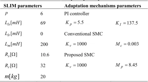
The parameters of the study system are listed in Table 2.
TABLE 2.The study of system parameters SLIM parameters Adaptation mechanisms parameters
p 6 PI controller
] [mH
Lls 69 Kp5.5 KI137.5
] [mH
Llr 0 Conventional SMC
] [mH
Lm 200 Kv1000 Mc0.003
] [ s
R 10.6 Proposed SMC
] [
r
R 32 Kv1000 Mp8.45
] [kg
M. H. Holakooie et al./ IJE TRANSACTIONS A: Basics Vol. 28, No. 7, (July 2015) 1011-1020 1020
Sensorless Indirect Field Oriented Control of Single-sided Linear Induction Motor
With a Novel Sliding Mode MRAS Speed Estimator
M. H. Holakooie, M. B. Banna Sharifian, M. R. Feyzi
Department of Electrical and Computer Engineering, University of Tabriz, Tabriz, Iran
P A P E R I N F O
Paper history: Received 12 January 2015
Received in revised form 21 March 2015 Accepted 11 June 2015
Keywords:
Indirect Field Oriented Control (IFOC) Model Reference Adaptive System (MRAS) Sensorless
Sliding Mode Control (SMC)
Single-Sided Linear Induction Motor (SLIM)
ﺪﯿﮑﭼ
ﯽﻘﻓو ﻊﺟﺮﻣ لﺪﻣ ﻢﺘﺴﯿﺳ ﮏﯾ ﻪﻟﺎﻘﻣ ﻦﯾا
(MRAS)
ﯽﺷﺰﻐﻟ ﺪﻣ لﺮﺘﻨﮐ ﺮﺑ ﯽﻨﺘﺒﻣ
(SMC)
ﺮﮕﺴﺣ نوﺪﺑ ﻮﯾارد ياﺮﺑ ار ﺪﯾﺪﺟ
رﺎﺷ راد ﺖﻬﺟ
(IFOC)
ﻪﻓﺮﻄﮑﯾ ﯽﻄﺧ ﯽﯾﺎﻘﻟا رﻮﺗﻮﻣ
(SLIM)
ﯽﻣ دﺎﻬﻨﺸﯿﭘ ﺪﻫد . ﻦﯿﻤﺨﺗ دﺮﮑﻠﻤﻋ يﺎﻫﺮﮔ
MRAS
ﻪﺑ
ﺖﺳا ﯽﻘﯿﺒﻄﺗ مﺰﯿﻧﺎﮑﻣ ﺮﯿﺛﺎﺗ ﺖﺤﺗ تﺪﺷ .
هﺪﻨﻨﮐ لﺮﺘﻨﮐ ،مﻮﺳﺮﻣ ترﻮﺻ ﻪﺑ
PI
ﯽﻣ بﺎﺨﺘﻧا فﺪﻫ ﻦﯾا ياﺮﺑ ﺖﺑﺎﺛ هﺮﻬﺑ ﻪﮐ دﻮﺷ
ﺪﻧﺰﻧ ﻦﯿﻤﺨﺗ ﯽﺘﺳرد ﻪﺑ ار ﺖﻋﺮﺳ ،ﻦﯿﺷﺎﻣ يﺎﻫﺮﺘﻣارﺎﭘ ﺮﯿﯿﻐﺗ ﻞﺜﻣ ﻒﻠﺘﺨﻣ ﻂﯾاﺮﺷ رد ﺖﺳا ﻦﮑﻤﻣ .
لﺮﺘﻨﮐ ،ﻪﻟﺎﻘﻣ ﻦﯾا رد هﺪﻨﻨﮐ
PI
ﺮﺑ ﯽﻨﺘﺒﻣ ﯽﻘﯿﺒﻄﺗ مﺰﯿﻧﺎﮑﻣ ﮏﯾ ﺎﺑ
SMC
ﮕﯾﺎﺟ ﺖﺳا هﺪﺷ ﻦﯾﺰ .
ﯽﺳﺎﺳا تﻼﮑﺸﻣ زا ﯽﮑﯾ
SMC
يﻻﺎﺑ ﺲﻧﺎﮐﺮﻓ مدﺎﺼﺗ
ﺪﯿﻠﮐ لﺮﺘﻨﮐ ﻊﺑﺎﺗ زا ﯽﺷﺎﻧ ﯽﻣ ﯽﻧز
ﺪﺷﺎﺑ . ﺖﺳا هﺪﺷ ﻪﺋارا ﺪﯾﺪﺟ ﯽﻧزﺪﯿﻠﮐ لﺮﺘﻨﮐ ﻊﺑﺎﺗ ﮏﯾ ،ﻞﮑﺸﻣ ﻦﯾا دﻮﺒﻬﺑ رﻮﻈﻨﻣ ﻪﺑ .
يﺎﻫﺮﺘﻣارﺎﭘ
SMC
ﯽﻣ ﻦﯿﯿﻌﺗ بﻮﺷآ يزﺎﺳ ﻪﻨﯿﻬﺑ ﻢﺘﯾرﻮﮕﻟا زا هدﺎﻔﺘﺳا ﺎﺑ ﻦﯾﻼﻓآ شور ﮏﯾ ﺎﺑ ﺪﯿﻗ ﭻﯿﻫ اﺮﯾز دﻮﺷ
ياﺮﺑ ﯽﺣاﺮﻃ
ﺎﻫﺮﺘﻣارﺎﭘ ﻦﯾا ﻦﯿﯿﻌﺗ ﺖﺳا هﺪﺸﻧ ﻪﺋارا
. ﮔ ﻦﯿﻤﺨﺗ دﺮﮑﻠﻤﻋ ﺮ
MRAS
ﺮﺑ ﯽﻨﺘﺒﻣ
SMC
يدﺪﻋ يزﺎﺳ ﻪﯿﺒﺷ زا هدﺎﻔﺘﺳا ﺎﺑ
ﯽﻣ ﺎﻫﺮﮔ ﻦﯿﻤﺨﺗ ياﺮﺑ ﻪﯿﺣﺎﻧ ﻦﯾﺮﺗ ﯽﻧاﺮﺤﺑ ﺖﻋﺮﺳ هزﺎﺑ ﻦﯾا اﺮﯾز ﺖﺳا هﺪﺷ ﯽﺠﻨﺳ رﺎﺒﺘﻋا ﻦﯿﯾﺎﭘ يﺎﻫ ﺖﻋﺮﺳ رد ﺎﺻﻮﺼﺨﻣ ﺪﺷﺎﺑ . ﻪﯿﺒﺷ ﺞﯾﺎﺘﻧ ﯽﻘﯿﺒﻄﺗ مﺰﯿﻧﺎﮑﻣ ﯽﯾارﺎﮐ يزﺎﺳ ﯽﻣ ﺪﯿﯾﺎﺗ ار يدﺎﻬﻨﺸﯿﭘ
ﺪﻨﮐ .