FLEXIBLE ANKLE BASED ON PKM WITH FORCE/TORQUE
SENSOR FOR HUMANOID ROBOT
Q. Liang*, Y. Wang
College of Electrical and Information Engineering, Hunan University, Changsha, Hunan, 410082, China [email protected], [email protected]
*Corresponding Author
(Received: July 11, 2011 – Accepted in Revised Form: September 15, 2011)
doi:10.5829/idosi.ije.2011.24.04b.08
Abstract This paper describes the development of a novel humanoid robot ankle based on an orientation Parallel Kinematic Mechanism (PKM) for intelligent and flexible control. With three identical Universal-Prismatic-Spherical prismatic-actuated limbs and a central Universal-Revolute passive limb, the PKM can perform three degrees of freedom rotational motions. In order to enable the humanoid robot safely to walk stably on the irregular environment, the control system should possess intelligence and flexibility. As the force information is one of the most important inputs for the control system, a novel integrated force sensor is designed to measure the action force and moment at the foot when humanoid robot maintains balanced or moves. The design possesses some interesting features such as high stiffness and compactness and is helpful for both reliable architectural design and performance improvement of the humanoid robot foot/ankle.
Keywords humanoid robot foot/ankle, parallel kinematic mechanism, flexible manipulation, force/torque sensor
1. INTRODUCTION
For decades, humanoid robots, which are designed to perform tedious, repetitive tasks, have become the focus of intensive research since they extends our capabilities in a wide variety of tasks and environment [1-3]. Over the past decade, several anthropomorphic robots have been constructed such as Wabot and Hadaly of Waseda University, Manny of Battelle’s Pacific Northwest Laboratory, Asimo of Honda, HRP of Kawada Industry and QRIO of Sony etc. Most of them have 1-DOF or 2-DOF feet/ankles, which restrict the flexibility and stability of the walking. Humanoid robot feet, which enable the robot to safely walk stably even
on the irregular ground, are not only the weight-bearing but also the shock-absorbing structure during ambulation. In recent years, a few works focused on reproducing the humanoid foot biomechanically, and several design of robot foot are created for prosthetic foots as well as for medical robots, but most existing designs are designed as simple serial kinematic mechanisms [4-5]. However, the serial mechanisms have many drawbacks such as poor dynamic performance and system stiffness duo to the serial nature. To be of interest for robot feet design, the parallel kinematic mechanisms should preserve higher accuracy, stronger stiffness and higher load-carrying capacity because of its closed-loop kinematic character.
.ﺖﺳﺍﺪﻴﻔﻣﺎﻤﻧﻥﺎﺴﻧﺍﺕﺎﺑﺭﺎﭘ
ﭻﻣ / ﺎﭘﺩﺮﮑﻠﻤﻋﺩﻮﺒﻬﺑﻭﺎﻳﺎﭘﻱﺭﺎﺘﺧﺎﺳﻲﺣﺍﺮﻃﻭﺩﺮﻫﻱﺍﺮﺑ ﻭﺪﻨﺷﺎﺑﻲﻣﻻﺎﺑﻲﮔﺩﺮﺸﻓﻭﻲﺘﺨﺳﺪﻨﻧﺎﻣﺐﻟﺎﺟﻱﺎﻫ
-ﻲﮔﮋﻳﻭﻲﺧﺮﺑﻱﺍﺭﺍﺩﻲﺣﺍﺮﻃﻦﻳﺍ .ﺖﺳﺍﻩﺪﺷﻲﺣﺍﺮﻃ،ﺪﻨﮐﻲﻣﺖﮐﺮﺣﺎﻳﺖﺳﺍﻝﺩﺎﻌﺗﻝﺎﺣﺭﺩﺎﻤﻧﻥﺎﺴﻧﺍﺕﺎﺑﺭﻪﮐ
ﻲﻧﺎﻣﺯﺎﭘﺭﺩﺭﻭﺎﺘﺸﮔﻭﻞﻤﻋﻱﻭﺮﻴﻧﻱﺮﻴﮔﻩﺯﺍﺪﻧﺍﻱﺍﺮﺑﺪﻳﺪﺟﻪﭼﺭﺎﭙﮑﻳﻲﻳﻭﺮﻴﻧﺭﻮﺴﻨﺳﮏﻳ،ﺪﺷﺎﺑﻲﻣﻝﺮﺘﻨﮐﻢﺘﺴﻴﺳ ﻱﺍﺮﺑ ﻱﺩﻭﺭﻭ ﻊﺑﺎﻨﻣ ﻦﻳﺮﺗ ﻢﻬﻣ ﺯﺍ ﻲﮑﻳ ﻭﺮﻴﻧ ﻪﺑ ﻁﻮﺑﺮﻣ ﺕﺎﻋﻼﻃﺍ ﻪﻜﻨﻳﺍ ﻪﺑ ﻪﺟﻮﺗﺎﺑ .ﺪﺷﺎﺑ ﻪﺘﺷﺍﺩ ﻱﺮﻳﺬﭘ ﻑﺎﻄﻌﻧﺍ ﻭﺵﻮﻫﺪﻳﺎﺑﻝﺮﺘﻨﮐﻢﺘﺴﻴﺳ،ﻢﻈﻨﻣﺎﻧﻂﻴﺤﻣﺭﺩﻦﻣﺍ ﻭ ﺭﺍﺪﻳﺎﭘﻦﺘﻓﺭﻩﺍﺭ ﻱﺍﺮﺑﺎﻤﻧﻥﺎﺴﻧﺍﺕﺎﺑﺭﻦﺘﺧﺎﺳﺭﺩﺎﻗﺭﻮﻈﻨﻣ ﻪﺑ .ﺪﻫﺩﻡﺎﺠﻧﺍﺍﺭﻲﺸﺧﺮﭼﺕﺎﮐﺮﺣﺯﺍﻱﺩﺍﺯﺁﻪﺟﺭﺩﻪﺳﺪﻧﺍﻮﺗﻲﻣPKM،ﻱﺰﮐﺮﻣﻲﻠﻛﻞﻌﻔﻨﻣ ﻮﻀﻋﻚﻳﻭﻱﻭﺮﮐ
،ﻱﺭﻮﺸﻨﻣ ﻲﻣﻮﻤﻋ ﻥﺎﺴﻤﻫ ﻮﻀﻋ ﻪﺳ ﻱﺮﻴﮔﺭﺎﻜﺑ ﺎﺑ .ﺪﻨﻛﻲﻣ ﻥﺎﻴﺑ ﻑﺎﻄﻌﻧﺍ ﻞﺑﺎﻗ ﻭ ﺪﻨﻤﺷﻮﻫ ﻝﺮﺘﻨﮐ ﻱﺍﺮﺑ (PKM)
To collaborate with humans and perform tasks in unstructured environment, the control of humanoid robot feet should have flexibility. This is why more and more studies on biped robot focus great attention to acquire the force information applied at the feet. Force sensor, which could measure the ground reaction force, plays an important role in flexible and stable locomotion, and several bio-robot feet have force sensor mounted at the ankle [6-10], but there is no one with integrated force sensor, which can make the bio-robot foot more compact and cost-effective.
In response to the above needs, a novel flexible humanoid robot foot/ankle based on a 3-DOF parallel kinematic mechanism with integrated force to enable humanoid walk and work more flexible and stable even in the undetectable or rough environment. The 3-DOF parallel mechanism is featured with a passive constraining limb and 3 identical limbs with prismatic actuators and could provide a spherical motion. The integrated sensor was newly modeled and integrated in the U-joint of the passive limb and could measure and provide tri-axis force. In particular, the cross shaft of the U-joint in the passive limb is modified and intended to be used as an elastic element of the force sensor.
The paper is categorized as follows: after description of the humanoid robot foot system and the using PKM, the kinematics problems of the PKM are investigated. Then, the orientation workspace of the PKM is calculated and stiffness of the PKM is performed which also lays a foundation for optimization study. Then the development of the integrated force sensor is introduced in detail.
2. DESCRIPTION OF THE HUMANOID ROBOT SYSTEM
The mechanism suit for the bio-robot foot/ankle joint should be able to provide a 3-DOF spherical motion (pitch, roll and yaw) just like a human ankle joint. In addition, to meet the trend towards high-speed natural walking/running and more humanoid gait, the mechanism suit for the bio-robot foot/ankle should also have high stiffness and low inertia characteristics. Therefore, the advantages of PKM make the mechanism with
3-DOF spherical motion a superior candidate for the next generation bio-robot foot/ankle.
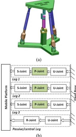
As shown in Figure 1 (a), the parallel mechanism consists of three identical actuated limbs of type UPS (Universal-Prismatic-Spherical) and one passive limb (central limb) of type UR (Universal-Revolute) with three degrees of freedom connection the moving platform and the fixed base. The passive limb is used to constrain the motion of the platform to only three degree of freedom of orientation. Figure 1 (b) shows the link-pair relationship diagram for the 3-DOF mechanism.
The uncolored boxes represent passive joints while the colored boxes represent active joint, and in this study, they are all prismatic joints.
The number of degrees of freedom, F, is given by the Chebyshev-Grubler-Kutzbach criterion:
1
( 1) 6 (9 11 1) 21 3
j i i
F n j f
(1) (a)
(b)
Figure 1. Spatial 3-DOF parallel mechanism with
where denotes the dimension of the space, n and
j denote the number of links and the number of joints, respectively, fi represents the degree of freedom associated with joint i.
Force information provided by the force sensor embedded in foot could be used for calculating ZMP [11], estimating real-time foot attitude [7], controlling and designing gait [9]. In our study, we try to integrate the force sensor into the foot mechanism.
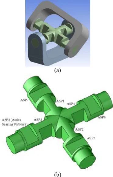
To measure the action force at the foot when the bio-robot maintains balance or moves, the cross shaft of the U-joint in the passive limb is modified and intended to be used as an elastic element of the force sensor, as shown in Figure 2 (a). The cross shaft connects fixed base and moving platform through upper hinge and lower hinge, respectively. As the passive limb can only rotate about its three axes and restrain the displacement motions along its three axes, it could be sensitive to the tri-axis force. The thin portions of the cross shift of the U-joint, as shown in Figure 2 (b), act as active sensing portions. The applied
force raises more significant strains on the thin portions than elsewhere, in particular, the elastic deformations and strains raised by the Fx (Fy) mainly occur on the Active Sensing Portion (ASP) 1,2 (3, 4); the elastic deformations and strains raised by the Fz mainly occur on the ASP 5, 6, 7, 8. Therefore, ASP 1-8, which are all located at the cross shift symmetrically, are employed as the candidate locations for strain transducers.
When the foot/ankle is mounted in the leg system, there will be a load applied onto the platform. As a consequence, each limb of the parallel mechanism undergoes corresponding force while the mechanism performs 3-DOF orientation motions. The corresponding forces are related to the moments the platform undergoes and their directions are along the limbs. To measure the force each limb bears, the top end of each limb is used as an elastic element.
3. KINEMATICS
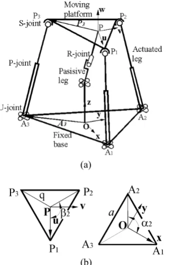
Figure 3 (a) shows a kinematically equivalent diagram of the proposed mechanism, in which squares and cylinders represent prismatic and revolute joints, respectively. The lower ends of the actuated limbs, points A1, A2, A3, are connected to fixed base through universal joints, and the upper end of the actuated limbs, points P1, P2, P3, are connected to the mobile platform through spherical joints.
For the purpose of convenience, a fixed reference frame O-xyzis attached to the fixed base at point Owith the z-axis normal to the base plane that contains points A1, A2 and A3 and the x-axis points along the direction of OA1. Similarly, a moving coordinate frame P-uvw is attached to the moving platform at point Owith the w-axis normal to the plane that contains point P1, P2, P3 and the
u-axis points along the direction of PP1, as shown in Figure 3 (b). The angle αi, βirepresent the angle between x-axis and the line OAi and the angle between u-axis and the line PPi, respectively. So, the position vector Aiwith respect to frame Oand
Piwith respect to frame Pcan be written as
[
0]
Ti i i
A
a c
a s
, for i=1, 2, 3, (2)[
0]
Ti i i
P
q c
q s
, fori=1, 2, 3, (3) (a)(b)
As the platform of the mechanism has three degrees of freedom, only three of the six Cartesian coordinates of the platform are independent, which have been chosen for convenience as (ψ, θ, φ).
The position of the moving platform is defined by the vector, P,
T
x y z
P OP p p p (4)
And the orientation of the moving platform is defined by the rotation matrix,
( ) ( ) ( )
O
P z y x
R
R
R
R
(5) where ψ, θ, φ (roll, pitch and yaw angles) represent three successive rotations of the moving frame about the fixed x, yand z-axis [11].As the passive limb is a 3-DOF serial chain, its posture can be described by the three joint variables, θ1, θ2, θ3. Referring to Figure 4, the coordinate frames are established and the corresponding Denavit-Hartenberg parameters are given in Table 1.
Hence, the D-H transformation matrices from
the moving platform to the fixed base can be obtained [12]
1 2 3 1 2 3 3 3 1
1 2
1 3 1 3 1 2 3
1 2 3 1 2 3 3 1 3
1 2
1 3 1 3 2 1 3
2 3 2 2 3 1 3 2 3
1 2 3
(--
)
(
-
-
)
-0
0
0
1
0 1
O O
O P
P P
c c c
c s
c c s
d c s
s s
s c
c c s
s c c
s s
s c s
d c c
c s
s c
c s s
s c
c
s s
d d s s
R P
T TTTT
(6)
Comparing Eq. (5) to (6), one can yield
1 2 cos c s( )
(7)
3
2 2
s c s
Atan2( , )
s c
(8)
1
2 2
s s s c c s c
Atan2( , )
s s
(9) (a)
(b)
Figure 3. Schematic representation of the 3-DOF parallel mechanism with prismatic actuators.
Figure 4. Coordinate frames of the passive
constraining limb with rigid links.
TABLE 1. The D-H Parameters of the Passive
Constraining Limb.
i ai di αi θi
0 0 d1 π/2 π/2
1 0 0 π/2 θ1
2 0 0 π/2 θ2
The inverse kinematics problem can be simply stated as: given the independent parameters, ψ, θ, φ, to find the corresponding lengths of the actuated limbs:
[ O P ] [T O P ]
i i P i i P i
l P A R P P A R P
(10) Since the mechanism possesses only three rotational degrees of freedom, the input vector can be written as q l l l 1, ,2 3T, and the output vector can be presented as the angular velocity of the moving platform, X x, y, zT. By using the velocity vector-loop method [13], we can obtain the Jocobian matrix of the mechanism A without the passive leg,
X
A = q
(11)where
T 1 1
T 2 2
T 3 3 P × s A= P × s P × s
(12)
And si is the unit vector pointing along the ith limb.
The Jocobian matrix of the passive constraining leg of the mechanism J can be expressed as [11]
1 2 3
1 1 2 2 3 3
4 1 3 4 1 2 3
1 2 3
2 1 3 1 3
4 1 3 4 2 3 1
4 2 1 3
1 2 3 1 3
4 2 3 4 3 2
1 1 2
1 1 2
2
( 4 (
) )
( (
) )
0 0 0
1 0
e e e
J
e r e r e r
d c c d c s s d c c c
c s s s s
d s c d s s s d c c s
c c s c s
d c s d c s
s c s
c c s
c
(13)Using the kinetostatic model [13], the compliance matrix for the rigid model can be derived as under the assumption that the actuators
(a)
(b)
(c)
are the main source of the compliance [13-15].
1
( ) ( ) T T
c
C J AJ C AJ J
(14)
where C=diag[c1, c2, c3], and ci is the compliance of the actuator of the ith limb.
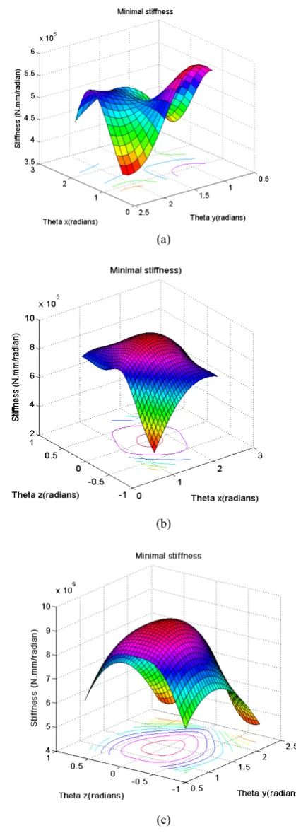
The minimal stiffness distributions are obtained after setting the stiffness values of all linear actuators to be 1000 N/m, as shown in Figure 5.
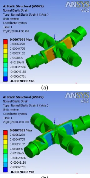
4. INTEGRATED FORCE SENSOR
As shown in the Figure 6 (a), the elastic strain mainly occurs on the thin portions of the modified cross shift of the U-joint of the passive limb under the force Fx along the x-axis, and the other side of the active sensing portions of the shift have the same distribution with reverse magnitude, as shown in Figure 6 (b). In addition, the maximum magnitude of the elastic strain occurs at the central side of the active sensing portions.
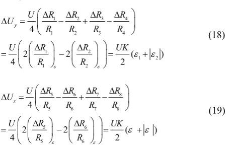
Figure 7 (a) shows the elastic normal strain occurs on the thin portions of the modified cross shift of the U-joint of the passive limb under force Fz along the z-axis, the other side of the active sensing portions of the shift have the similar distribution with reverse magnitude. And the maximum magnitude of the elastic strain occurs at the central side of the active sensing portions.
If no external force or moment is applied to the limb, each limb can be treated as a binary link, which means the links only bear tension or compression forces. As shown in the Figure 7 (b), the elastic strain mainly occurs on the thin portions of the limb. According to the principle of virtual work, the virtual work contributed by all the active forces can be written as
T T
X q
w
f
(15)(a)
(b)
Figure 7. (a) The normal elastic strain occurred on the modified cross shift of U-joint of the passive limb under the applied Force Fz, (b) the normal elastic strain occurred at the end of the limb.
(a)
(b)
Figure 6. The normal elastic strain occurred on the modified cross shift of the U-joint of the passive limb under the applied force Fx (similar to Fy): (a) the front
where
X ,
q represent the vector of virtual displacements associated with the moving platform and actuated limbs, respectively. Eq. (15) can be rewritten asT T
w X f q (16)
where w=[Mx,My,Mz]Tis the vector of the moving platform output moment, i.e. the moment applied to the platform, and f=[f1,f2,f3]T represents the vector of actuator force, i.e. the force that the actuated limb undergoes.
Substituting Eq. (11) into (15) yields T
w A f
(17)Hence the moments applied on the moving platform can be calculated from the actuated limb forces, and vice versa.
It is important to bond the strain gauges onto proper place and orientation on the force-sensing element, which is always chosen by regarding to the places having maximum strains and the orientations alone the orientations of maximum stresses, to get the maximum sensitivity and repeatability [16]. All gauges considered in the present study are Y series linear strain gage (1-LY11-3/120) made in HBM Inc. The measuring grid foil of the gauges is made of constantan and the nominal resistance is 120 Ohm.
Based on strain analysis mentioned above, the positions conducive for strain gauges to detect strain are the central sides of the active sensing portions. Therefore, we select the spots where have the maximum strain to arrange the strain gauges to detect the axial strains arose by loads. as shown in Figure 8 (a), we arrange strain gauges R1, R2, R3, R4 on active sensing portion 1, 2 along the radial direction (x-axis) as group Y to detect the force Fy along the y-axis; strain gauges R5, R6, R7, R8 on active sensing portion 3, 4 along the radial direction (y-axis) as group X to detect the force Fx along the x-axis. On the active sensing portion 5, 6, 7, 8, we arrange strain gauges R9, R10, R11, R12 along the radial direction as group Z to detect the force Fx alone z-axis. On the active sensing portions of limb 1, 2, 3, strain gauges R13-R14, R15 -R16, R17-R18 are bonded at the central spots, respectively, as shown in Figure 8 (b).
To convert the change in resistance due to strain to a voltage proportional to strain a measuring circuit is used. According to the arrangement scheme of strain gauges, the Wheatstone bridges connection mode of the sensor is determined, as shown in Figure 9. The strain gauges of groups X, Y and Z are all connected to full-bridge circuits, in which every bridge arm is a strain gauge. The other three groups are connected to half-bridge circuits, in which every group has two strain gauges.
When the sensor is applied single force/torque Fx, Fy, Fz respectively, corresponding output of each bridge is:
3
1 2 4
1 2 3 4
1 2
1 2
1 2
4
2 2
4 2
y
R
R R R
U
R R R R
R R
U UK
R R
(18)
5 6 7 8
5 6 7 8
5 6
5 6
5 6
4
2 2
4 2
x
R R R R
U
R R R R
R R
U UK
R R
(19) Figure 8. Strain gauges arrangement: (a) on the cross shift, (b) on the first actuated limb.
Figure 9. Wheatstone bridges connection mode.
( )
U
U
15 16 17 18 15 16 17 18
15 16
15 16
15 16
4
2 2 ( )
4 2
z
R R R R
U U
R R R R
R R
U UK
R R
(20)
where K is the sensitivity coefficient of the strain gauges,
is the elastic strain at the spot where the Ri is bonded on the diaphragms, U is the excitation voltage, and ( R / R ) i i ε means change rate of the resistance of the strain gauge Ri due to strain variation.And the corresponding output of each limb which is proportional to force that the actuated limb undergoes can be calculated as
14
14
13 13
13
13 13
2 ( )
4 4 2
limb1
R R R
U U UK
U
R R R
(21)
15 1 15
15
15 15
6
1 6
2 ( )
4 4 2
lim b2
R R R
U U U K
U
R R R
(22)
17 1 17
17
17 17
8 18
2 ( )
4 4 2
limb1
R R R
U U UK
U
R R R
(23)
After calibration, the outputs of the circuits and the force will have a linear relationship, based on the Eq. (17-23), the axis forces and three-axis moments applied on the moving platform could be calculated. Finally, as integrated sensors measure equivalent forces acting on the moving platform which differs from the forces applied on the foot/ankle. It is therefore necessary to transform forces from the moving platform’s frame into the foot/ankle’s frame:
0
( )
c
c s s
c c c
c c s s s
f R f
m S r s R R m
(24)
which requires knowledge of the position of the origin of Frame s with respect to Frame c as well as of the orientation of Frame s with respect to Frame c. And S(*) are the skew-symmetric operator with the notation:
0 ( )
0
z y
z y x
y x r r S r r r r
r r (25) 5. CONCLUSION
In this paper, a kind of PKM with three actuated limbs and a central passive limb connecting the moving platform and the fixed base is proposed, which is used as a humanoid robot ankle. A force sensor that can provide three-axis forces and three-axis moments is integrated into the PKM by modifying the universal joint of the passive limb and the ends of the actuated limbs. Kinematic problem is discussed to acquire the knowledge of the performance of the proposed PKM. The elastic strain occurs on the elastic element of the force sensor is analyzed via ANSYS. The arrangement of the strain gauges and the Wheatstone bridges connection mode are presented. For future works, the manufacture of the prototype, the gait control and calculation of ZMP based on the force information provided by the integrated force sensor will be performed.
ACKNOWLEDGEMENTS
This work was supported by the Fundamental Research Funds for the Central Universities, Hunan University. The authors gratefully acknowledge Prof. Y. Ge (Institute of Intelligent Machines, Chinese Academy of Sciences) and Prof. D. Zhang (University of Ontario Institute of Technology) for their great supports.
6. REFERENCES
1. Kato, J., “pneumatically powered artificial legs walking automatically under various circumstances”, Proc. of 4th Int. symposium in external control of human extremities, (1972), 458-470.
2. Carson, M.C., Harrington, M.E., Thompson, N. O’connor, J.J. and Theologis, T.N., “Kinematic analysis of a multi-segment foot model for research and clinical applications: a repeatability analysis”, Journal of Biomechanics,Vol. 34, Issue 10, (2001), 1299-1307,
DOI: 10.1016/S0021-9290(01)00101-4.
3. Korayem, M. H. and Ahmadi, R., “Design, Modeling, Implementation and Experimental Analysis of 6R Robot”,International Journal of Engineering,
Vol. 21, Issue 1, (2008), 71-84,
4. Chen, W.P., Tang, F.T. and Ju, C.W., “Stress distribution of the foot during mid-stance to push-off in barefoot gait: a 3-D finite element analysis”, Clin Biomech, Vol, 16, (2001), 614-620. DOI:
10.1016/S0268-0033(01)00047-X.
System to Measure Standing Pose of the Foot Using Distributed Triaxial Force Sensor", Engineering in Medicine and Biology Society,. 28th Annual International Conference of the IEEE, (2006),
1482-1486, DOI: 10.1109/IEMBS.2006.259400.
6. Kim, G.S., "Development of 6-axis force/moment sensor for a humanoid robot's foot", Science, Measurement & Technology, IET, Vol. 2, No. 3,
(2008), . 122-133, DOI: 10.1049/iet-smt:20070019. 7. Li, J., Huang, Q., Zhang, W., Yu, Z. and Li, K.,
"Real-time foot attitude estimation for a humanoid robot based on inertial sensors and force sensor", Robotics and Biomimetics, 2008. ROBIO 2008. IEEE International Conference on, (2009), 365-370, DOI:
10.1109/ROBIO.2009.4913031.
8. Krkljes, D., Nagy, L., Nikolic, M. and Kalman, B., "Foot force sensor - Error analysis of the ZMP position measurement", Intelligent Systems and Informatics, 2009. SISY '09. 7th International Symposium on,
(2009), 221-226, DOI: 10.1109/SISY.2009.5291161. 9. Liu, L., Zhao, M., Lin, D., Wang, J. and Chen, K., "Gait
designing of biped robot according to human walking based on six-axis force sensors", Computational Intelligence in Robotics and Automation, 2003. Proceedings. 2003 IEEE International Symposium on,
(2003), 360- 365 Vol. 1, DOI: 10.1109/CIRA.2003.1222116.
10. Kalamdani, A., Messom, C., Siegel, M., "Robots with Sensitive Feet", Instrumentation & Measurement
Magazine, IEEE, Vol. 10, No. 5, (2007), . 46-53, DOI:
10.1109/MIM.2007.4343567.
11. Tsai, L. W., 1999, Robot Analysis: The Mechanics of Serial and Parallel Manipulators, John Wiley & Sons,
New York. ISBN: 0471329537.
12. Birglen, L. and Gosselin, C.M., “a new 3-dof haptic device”, IEEE Transactions on Robotics and Automation, Vol. 18, No. 2, (2002), . 166-175. DOI:
10.1109/TRA.2002.999645 .
13. Liang, Q., Zhang, D., Song, Q. and Ge, Y., “Six-DOF micro-manipulator based on compliant parallel mechanism with integrated force sensor”, Robotics and Computer-Integrated Manufacturing, Vol. 27, Issue 1,
(2010), . 124-134, DOI: 10.1016/j.rcim.2010.06.018. 14. Gosselin, C., and Angeles, J., “The optimum kinematic
design of a planar three-degree of-freedom parallel manipulator”, Trans. ASME, J. Mech., and Auto in design, Vol. 110, (1988), 35-41.
15. Gosselin, C.M. and Angeles, J., “A global performance index for the kinematic optimization of robotic manipulators”, ASME Journal of Mechanical Design,
Vol. 113, No. 3, (1991), 220--226. DOI: 10.1115/1.2912772.
16. Liang, Q., Zhang, D., Ge, Y. and Song, Q., "A Novel Miniature Four-Dimensional Force/Torque Sensor With Overload Protection Mechanism", Sensors Journal, IEEE, Vol. 9, No. 12, (2009), .1741-1747, DOI: